

L. Pradeep Raja
School of Electrical and Electronics Engineering, SASTRA University, India
R. Balasubramanian
School of Electrical and Electronics Engineering, SASTRA University, India
K. Parkavi Kathirvelu
School of Electrical and Electronics Engineering, SASTRA University, India
Rengarajan Amirtharajan
School of Electrical and Electronics Engineering, SASTRA University, India
Information Technology Journal
Year: 2014 | Volume: 13 | Issue: 16 | Page No.: 2574-2580


ABSTRACT
This study presents a new Space Vector Pulse Width Modulation (SVPWM) based stator oriented non-linear control of induction motor drive system using MATLAB/Simulink environment. The non-linear control is employed in the stator by making a small change in the variable transformation and this control technique will not affect the system dynamics and improves the performance in all four quadrants. This reduces size and cost of the induction motor drive system. The steady state and transient response of the drive system is observed in all the four quadrants and their torque and speed characteristics were studied. This non-linear control in this system is better compared to other systems. The motor drive is simulated in all four quadrants and their waveforms were plotted.
PDF Abstract XML References Citation
Article History
Received: April 15, 2014;
Accepted: August 16, 2014;
Published: September 29, 2014
How to cite this article
L. Pradeep Raja, R. Balasubramanian, K. Parkavi Kathirvelu and Rengarajan Amirtharajan, 2014. SVPWM Based Stator Oriented Non-linear Control of Induction Motor Drives. Information Technology Journal, 13: 2574-2580.
DOI: 10.3923/itj.2014.2574.2580
URL: https://scialert.net/abstract/?doi=itj.2014.2574.2580
DOI: 10.3923/itj.2014.2574.2580
URL: https://scialert.net/abstract/?doi=itj.2014.2574.2580
INTRODUCTION
Induction motors are the workhorse of the industry since they are widely used in industrial drives. Induction motors are cheap, suitable for hazardous environment and easy to control (Abdalla et al., 2011). There are different types of induction motor drives which are reported in the literature and are classified based on the control techniques available for controlling the parameters like voltage, frequency and current fed to the motor (Dandil et al., 2005). Many researchers have done on Direct Torque Control (DTC) (Fakhfakh et al., 2006) and Flux Oriented Control of induction motors drive to operate in only one quadrant. There are so many intelligent controllers also used for control of inverters (Kang and Jin, 2010; Ustun, 2007). The major drawback of aforementioned techniques is occurrence of non-linearity during the change in flux linkage of the rotor present in the mechanical part which is not considered for the control purpose.
This study proposes a new method to overcome the aforementioned disadvantage. In this method, a small change is made in the variable transformation of rotor flux so that the flux linkage in the rotor can be changed without affecting the dynamics of the system. Space Vector Pulse Width Modulation (SVPWM) which is used widely for its superior performance is employed to eliminate the lower order harmonics. The drive is made to be operated in all the four quadrants such as forward motoring, forward braking, reverse motoring and plugging by stator oriented non-linear control. The prime benefit of this method is SVPWM control method which is used for non liner control. The proposed method is simulated using Simulink platform in the MATLAB software.
STATOR ORIENTED NON-LINEAR CONTROL SYSTEM
Figure 1 shows the block diagram of stator oriented non-linear control of induction motor drive system. This system consists of voltage fed induction motor drive in which the inverter switches are controlled by Space vector Pulse Width Modulation technique. The drive current and voltage is taken as reference and fed to the computational block in which the non-linear dynamic problems in the system are considered and rectified. The speed regulation, rotor current calculation and flux are processed in computational block. Then the processed values are compared with the actual values in the PI controller. The output of the PI controller is a two-phase quantity. The transformation of two-phase to three-phase quantities is done in variable transformation block. The output of the variable transformation is stator current (Is) and speed (ωi). The current controller compares the inverter current and feedback current to generate the Space Vector Pulses and control the switches with their modulation index.
In the literature survey, majority works deals the induction motor drive controllers for only single quadrant operation and control is linear but this proposed system in the induction motor is operated in all four quadrants and provides the stator oriented non linear control. The SVPWM technique which is suitable for variable frequency drive is employed in this study.
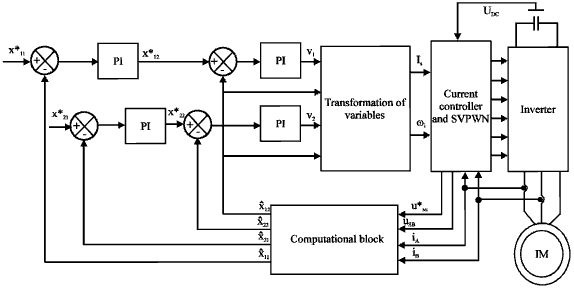 | |
| Fig. 1: | Stator oriented nonlinear control of four quadrant drive system using induction motor |
In previous methods, the stator reference control and non-linear control is done separately leads to bulky size of the system (Luo et al., 2009). In the proposed system, non-linear control technique is implemented along with stator reference frame with the slight change in the variable transformation. Both the transformation and control are done on the stator simultaneously, so that cost and size of the system reduces.
In this control, the motor is operated in stationary reference frame and the current in the stator shown in X-axis is assumed not to be stationary (Benheniche and Bensaker, 2012). The following equations describe the steady state and transient electromagnetic behaviour of induction motor drive:
 | (1) |
 | (2) |
 | (3) |
 | (4) |
 | (5) |
Where:
 |
 | (6) |
where, isxy is the shunt current, Ψsxy is the shunt flux, Usxy is the stator voltage, ωs is the rotor speed. Ls, Lr, Lm is the stator, rotor, mutual inductances. While Rs, Rr are the stator and rotor resistances.
State variable accessibility is very important when employing a non-linearity feedback to obtain linearity of the control system (Ershadi et al., 2010). It is presumed that all important variables are calculated directly and measured by a system of observer or model system. The non-linear model with variable transformation enables the control strategy to control efficiently. Hence, the new changes that are made in the variable transformation give a better response in the induction motor drive:
 | (7) |
 | (8) |
 | (9) |
 | (10) |
The drive system is converted into linear model by including the non-linear model variable transformation equations. The PI controller compares the actual and reference values of the current to employ the designed control. The kp and ki values of the PI controller are obtained by tuning the system by trial and error method.
Current controllers control the parameter stator current (Is) that flows through the stator winding and generates the space vector pulses to the switches of the inverter fed induction motor drive. The control variables x11, x12, x22 are the output signals of the speed controller, current controller’s rotor flux, speed and torque calculation using control feedback. The error signal from comparison generates the SVPWM pulses by comparing the reference and actual values.
Inverter model: A 3 phase, 6 pulse inverter has been modelled by assuming ideal switches in which the on state losses are neglected. The inverter is fed to an induction motor drive and switching pulses are given by the non-linear feedback of Space vector pulses:
 |
SPACE VECTOR PULSE WIDTH MODULATION (SVPWM)
There are many PWM techniques which are available for inverter control (Balasubramanian et al., 2014) SVPWM is the advanced technique used in industrial drives to obtain high DC bus voltage (Bose, 2006). The space vector can be done both for transient and steady state conditions with phasor representation. Over modulation is possible in SVPWM so that the triple end harmonics gets eliminated and the power factor gets stabilized. It consists of 6 active vectors from v1 to v6 and two null vectors vo and v7 (Fig. 2). The size of active vectors depends upon the number of sectors. The DC link voltage appears as same as in the input. This method overcomes the disadvantage of other PWM techniques that are given in the literature (Habetler et al., 1992; Ravi Teja et al., 2012):
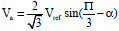 | (11) |
 | (12) |
 | (13) |
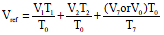 | (14) |
 | (15) |
MATERIALS AND METHODS
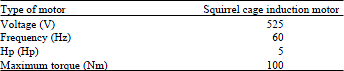
System configuration: The following assumptions are made in the induction motor, air gap should be uniform, rotor and stator windings should be balanced and the effect of saturation is neglected which is presented in Table 1. Since, the induction motors are cheap, flexibility of AC network finds enormous applications in the field of drives (Abu-Rub et al., 2012).
| Table 1: | Induction motor system configuration |
 | |
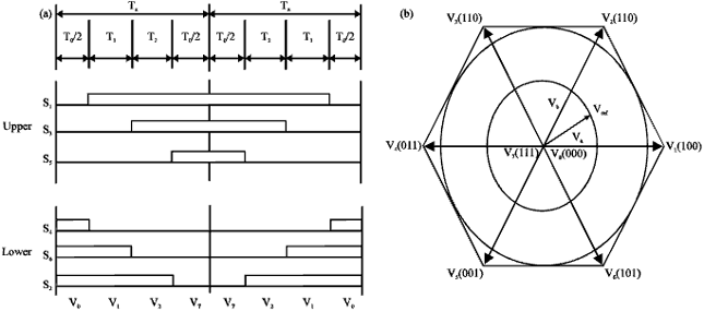 | |
| Fig. 2(a-b): | Symmetrical PWM pulse pattern in (a) First sector and (b) Vector diagram |
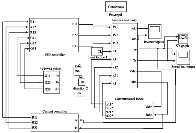 | |
| Fig. 3: | Simulink model of SVPWM based non-linear control of induction motor drive |
The induction motors find their popularity in drives because the speed of the motor can be controlled very easily (Krishnan, 2010). The induction motor drive is made to be operated in all four quadrants without varying the dynamics of the system.
SIMULINK MODEL SVPWM BASED NON-LINEAR CONTROL OF INDUCTION MOTOR DRIVE
The MATLAB/Simulink model Fig. 3 of stator oriented non-linear control of induction motor drive is shown in the figure. The drive is operated in all the 4 quadrants such as forward motoring, reverse motoring, forward braking and plugging. The inverter and motor block consist of 3 phase, 6 pulse inverter and induction motor drive. The output voltage and current are taken as feedback and given to computational block which performs non-linear control by using state space variables. The speed and stator current feedback is given to the current controller which generates error signals and given to the PI controller. The PI controller compares the actual and reference values of the current controller and generates SVPWM pulses. The speed, torque and current waveforms of the simulation are observed in all four quadrants of induction motor drive system.
RESULTS AND DISCUSSION
The waveforms that describes about the 4 quadrant operation are as shown in the Fig. 4-7, respectively. The drive performance is analysed in all four quadrants.
First quadrant operation: Initially the motor starts and run in first quadrant. During starting the current in the stator windings oscillates and settles at 0.18 sec. The motor speed also gradually increases up to 0.18 sec after that it saturates and runs at constant speed of 1750 rpm. Simultaneously motor torque is also oscillates for the period of 0.1 sec and settle down as shown in Fig. 4 and 5. In this control, the settling time of the drive is improved to 0.18 sec. In first quadrant both voltage and current are positive and drive operates in first quadrant.
Second quadrant operation: In second quadrant, the phase sequence of the motor is reversed, forward braking takes place at 0.4 sec due to reversal of current. The speed of the drive gets reduced slowly and reaches zero at 0.6 sec as shown in Fig. 5. Figure 4 and 5 shows the second quadrant operation of drive in which voltage is positive and current is negative. Motor torques as well as current both is dropped to zero.
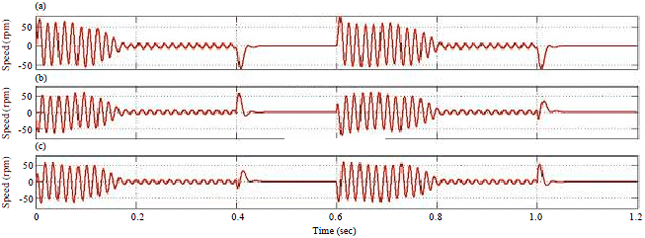 | |
| Fig. 4(a-c): | Stator current wave form in all four quadrants of duction motor drive for (a) A phase, (b) B phase and (c) C phase |
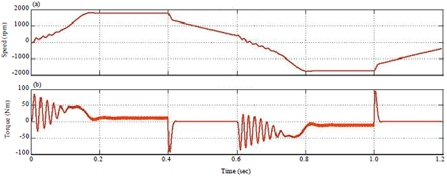 | |
| Fig. 5(a-b): | (a) Speed and (b) Torque waveform in all four quadrants |
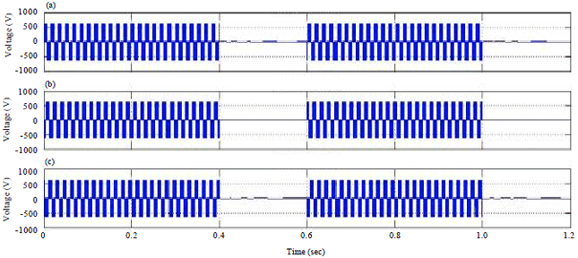 | |
| Fig. 6(a-c): | Inverter output voltage for (a) A phase, (b) B phase and (c) C phase |
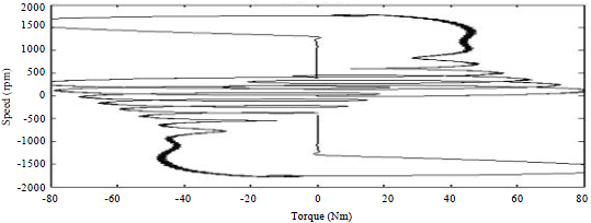 | |
| Fig. 7: | Speed vs. torque characteristics in all four quadrants |
Hence, forward braking operation takes place in second quadrant and the drive comes to standstill.
Third quadrant operation: After initiation of third quadrant operation, the motor starts to run in reverse direction. The torques’s as well as current both are negative. Figure 4 shows the initiation of third quadrant operation at 0.6 sec then the motor current start oscillating and settles down at 0.7 sec. The motor speed and torque oscillations are shown in Fig. 5 which shows that settling time of the drive is less with nonlinear control. In third quadrant operation both the voltage and current are negative.
Fourth quadrant operation: At 1 sec reverse braking is applied and the speed of the drive reduces slowly by the designed controller. In fourth quadrant plugging operation takes place. Figure 4 shows the variation of current and torque after initiating fourth quadrant operation. Figure 4 and 5 shows the torque developed by the drive is negative and settled at zero speed. In fourth quadrant voltage is negative and current is positive. Thus the operation of motor in fourth quadrant is verified. Overall inverter output voltage is shown in Fig. 6 and the speed vs. torque characteristics in all four quadrants presented in Fig. 7.
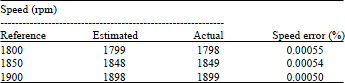
Table 2 shows the rotor speed response analysis of induction motor drive. It has been noticed that the speed control is more accurate. The percentage error values are limited to 0.0005%. Hence, the stator oriented nonlinear control has precise control of speed compared to other control techniques (Ustun, 2007). When the induction motor is shifted from one quadrant to other then speed oscillations takes place and in this proposed method the speed oscillations are limited to 0.1 sec.
| Table 2: | Rotor speed response analysis |
 | |
CONCLUSION
The simulation result shows that the induction motor drive is operating successfully in all four quadrants by using the designed stator oriented non-linear control. The simulation result also shows that the performance of the induction motor drive such as settling time and transition from each quadrant are improved. The stator oriented non-linear control has better steady state and transient response in all the four quadrants. Introducing the non-linear control in stator part by variable transformation causes reduction in the size and cost of the drive system. The dynamic response in all the four quadrants was better than the systems that are reported in the literature. The future scope of this study can be extended by employing multilevel inverter.
REFERENCES
- Abdalla, A.N., R. Ghoni and N.F. Zakaria, 2011. Simulation model of space vector modulated control matrix converter-fed induction motor. J. Applied Sci., 11: 768-777.
CrossRefDirect Link - Balasubramanian, R., K.P. Kathirvelu and R. Amirtharajan, 2014. Analysis of multi level current source inverter: A critic based on various PWM control strategies. Res. J. Inform. Technol., 6: 166-177.
CrossRefDirect Link - Benheniche, A. and B. Bensaker, 2012. Simulation of non linear adaptive observer for sensorless induction motor control. Proceedings of the 1st International Conference on Renewable Energies and Vehicular Technology, March 26-28, 2012, Hammamet, Tunisia, pp: 484-489.
CrossRef - Dandil, B., M. Gokbulut and F. Ata, 2005. A PI type fuzzy-neural network controller for induction motor drives. J. Applied Sci., 5: 1286-1291.
CrossRefDirect Link - Ershadi, M.H., M. Moallem and M. Ebrahimi, 2010. Loss-minimization scheme in modified DTC-SVM for induction motors with torque ripple mitigation. J. Applied Sci., 10: 2269-2275.
CrossRef - Fakhfakh, A., S. Feki, Y. Herve, A. Walha and N. Masmoudi, 2006. Virtual prototyping in power electronics using VHDL-AMS application to the direct torque control optimisation. J. Applied Sci., 6: 572-579.
CrossRefDirect Link - Habetler, T.G., F. Profumo, M. Pastorelli and L.M. Tolbert, 1992. Direct torque control of induction machines using space vector modulation. IEEE Trans. Ind. Applic., 28: 1045-1053.
CrossRefDirect Link - Kang, P. and Z. Jin, 2010. Neural network sliding mode based current decoupled control for induction motor drive. Inform. Technol. J., 9: 1440-1448.
CrossRefDirect Link - Luo, H., Y. Lv, X. Deng and H. Zhang, 2009. Optimization of adaptation gains of full-order flux observer in sensorless induction motor drives using genetic algorithm. Inform. Technol. J., 8: 577-582.
CrossRefDirect Link - Ravi Teja, A.V., C. Chakraborty, S. Maiti and Y. Hori, 2012. A new model reference adaptive controller for four quadrant vector controlled induction motor drives. IEEE Trans. Ind. Electron., 59: 3757-3767.
CrossRefDirect Link - Ustun, S.V., 2007. GA-based optimization of PI speed controller coefficients for ANN-modelled vector controlled induction motor. J. Applied Sci., 7: 4001-4006.
CrossRefDirect Link
TOUFOUTI Reply
GOODE PAPER