
Li Liu-Sheng
JiangXi University of Technology, 330029, Nanchang, China
Chen Jun
JiangXi University of Technology, 330029, Nanchang, China
Journal of Applied Sciences
Year: 2014 | Volume: 14 | Issue: 2 | Page No.: 188-192


ABSTRACT
In this study, a method was put forward for structural damage qualitative and localization based on acceleration frequency response. The proportional damping of the dynamics model in this method is damping matrix, then deduce the criterion of damage and formulas of damage quantitatively, at last get the damaged condition by the least square method. This method have definite physical interpretation, avoid modal analysis, very useful in real-time environmental monitoring. At last the calculation process of an example using this method is demonstrated, which tests it was validity.
PDF Abstract XML References Citation
Received: May 20, 2013;
Accepted: January 02, 2014;
Published: February 01, 2014
How to cite this article
Li Liu-Sheng and Chen Jun, 2014. Structural Integrated State Evaluation Base on Acceleration Frequency Response Function. Journal of Applied Sciences, 14: 188-192.
DOI: 10.3923/jas.2014.188.192
URL: https://scialert.net/abstract/?doi=jas.2014.188.192
DOI: 10.3923/jas.2014.188.192
URL: https://scialert.net/abstract/?doi=jas.2014.188.192
INTRODUCTION
Damage detection is the basis of structural health monitoring, has long been a very active research field, so the number of the damage detection method growth rapid. Yang and Yu (2004) and Sohn and Farrar (2001) proposed 5 levels of damage detection based on the research of Rytter et al. (2000): (1) To identify whether the structure of damage; (2) To determine the location of damage; (3) Identify the types of damage; (4) Quantify severity damage; (5) To determine the remaining life of structures. And most of damage detection which can reach third, fourth, fifth levels is less, the reason is the lack of methods to quantify the extent of the damage. Chiu et al. (2000) observe the degree of damage through the curve of frequency response function and transfer function, but they did not achieve the degree of quantization. Zheng et al. (2001) using curvature FRF change location and recognition effect of single damage structure obviously, but cannot do quantitative identification. Ceng Shenchang (Zeng and Mai, 2004) accurate positioning for the multiple damage structure using the method of combining frequency response function and neural network, but the error in quantitative analysis is large. Guo and Li (2007) get the structure damage localization and quantification state using incomplete frequency response function, but only applicable to the structure less degrees of freedom. Yang et al. (2006) proposed the damage identification method based on acceleration frequency response functions according to a statically determinate beam, but the example model is too simple, there is certain difficulty to damage identification of large structures.
Because the acceleration frequency response functions can be directly obtained by calculation and measurement, bypassing the modal analysis, the modified FRF response function model is consistent with the actual structure (Xu et al., 2002), so the model updating technique based on acceleration frequency response functions has more practical Eng. significance in structural damage detection. By this, the study research on a structural damage detection method use acceleration frequency response functions obtained in the structure vibration test and analysis results.
MATHEMATICAL MODEL
Acceleration frequency response functions: Based on the discretization of continuum structure, obtained n degrees of freedom dynamic equations by finite element method (Liu and Du, 2005):
| (1) |
Which [M], [C], [K] were nxn mass, damping and stiffness matrices. {x (T)} is n-dimensional column vector displacement; {f (T)} is n-dimensional external load series vector.
Fourier transform the Eq. 1 to obtain the frequency response function of the structure (Lee and Shin, 2002):
| (2) |
where, [H (ω)] nxn order matrix.
Fourier transform of the displacement frequency response function derivation again get the speed frequency response function [Hv (s)] with the acceleration frequency response function [Has)], as follows:
| (3) |
| (4) |
According to Eq. 1 to 3 can be drawn displacement, velocity, acceleration frequency response function of the relationship:
| (5) |
According to the analysis of the sensitivity of the dynamic test data, the test data of high precision using FRF acceleration, so the acceleration frequency response functions as a source of dynamic test data.
Structural damping matrix (Rayleigh): Rayleigh damping (Greco and Santin, 2002) is simple, convenient and it has been widely used in dynamic analysis of structures. The damping matrix of Rayleigh damping assumption structure is the combination of the mass matrix and stiffness matrix, i.e.:
| (6) |
where, a0 and a1 are the two proportional coefficient, respectively with s-1 and s dimension.
The mass matrix and stiffness matrix are modes of standardization, can get:
| (7) |
| (8) |
Therefore, the damping matrix satisfying the vibration standard, can be expressed as:
| (9) |
where, {φ} is the structural free vibration of nx1 modes.
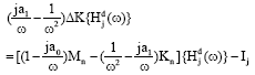
Acceleration frequency response functions based on rayleigh damping: Substituting Eq. 9 into 4. This study only use acceleration frequency response function as the test data source, expression of the frequency response function H (ω) instead of the expression of the acceleration frequency response function, get the acceleration frequency response function based on Rayleigh damping:
| (10) |
ASSESSMENT METHOD
Qualitative analysis: According to Eq. 10 were obtained frequency response function matrix of [Hu(ω)] and [H d(ω)] with n degrees of freedom system structure in lossless and damage condition. Judging the damage existence by the change of matrix:
| (11) |
Without considering other external conditions, if the structure does not exist damage, then the ΔH (ω) value is zero. If the reflected by continuous frequency excitations graphics, Δ Hij (ω) is frequency response obtained offset size graphics that j excited i point. If the structure has damage, then the graphic offset.
Damage index initial positioning: Equation 10 can be transformed into the following form:
| (12) |
where, I is the nxn matrix.
The damage won't assume structure changed its quality features, but will change the stiffness characteristics (Li and Li, 2002). The damage situation, structural stiffness matrix is expressed as:
| (13) |
In the equation, [ΔK], [H d(ω)] denote the stiffness change after damage and the frequency response function matrix. Stiffness damage [ΔK] expressed as the sum of product of each unit matrix and the degree of damage (Shi et al., 2000). Therefore, [ΔK] can be expressed as:
| (14) |
In the dynamic test of measurement of large civil Eng. structure, the test FRF every point is not easy, so use [Hd(ω)] j column measurement data {Hjd(ω)}, the above equation becomes:
| (15) |
In the equation, Ij is the identity matrix I column j.
Then, can be transformed into the type (15):
 | (16) |
Consider the relationship type (16), the equation is:
| (17) |
Make:
| (18) |
where, {ζ} is the damage index before and after the damage, it can be constructed through the non-destructive condition [Hd(ω)] and after damage the j column measurement data {Hjd(ω)}.
Substituting Eq. 18 into Eq. 17:
| (19) |
where, {ζ} can be used as the discrimination index of the damage location. The ζi is row i of the damage index first, the corresponding configuration is the i-th DOF. If ζi is not zero, which corresponds to the i-th degree of freedom related with damage elements.
Quantitative equations: According to the Eq. 16, 18, 19 can be rewritten as:
| (20) |
It is an equation on damage degree {δα}, obtain the equation:
Where:
| (21) |
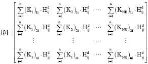 | (22) |
where, Hijd(ω) is a line i column vector numeric measured frequency response functions after damage. [β] is nxNE dimension matrix, the basic components of it can be expressed as:
| (23) |
where, (Ks)mi is the value in the global coordinate system of the s element stiffness matrix of the line mi column.
Least square solution: The freedom degree in Eq. 19 is greater than the unit number as NE<n. Therefore, to solve the equation actually means finding NE corresponding αi to get the minimum value of [β] {α} = {ζ}, it also can be expressed as following:
| (24) |
To get the extreme value of {E2} is to make its differential zero as following:
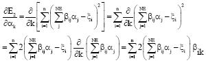 | (25) |
The following is the above equation expressed with matrix:
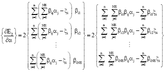 | (26) |
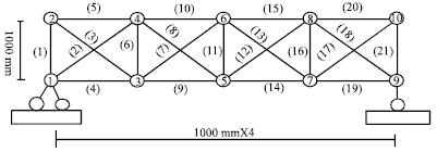 | |
| Fig. 1: | Finite element model of truss |
The column vector {δα} of damage coefficient of each unit can be acquired by the above equation:
| (27) |
NUMERICAL SIMULATION
As shown in Fig. 1, the size of plane truss structure is in the left and bottom of the figure, the node number of the finite element model is in truss node and the unit number is on the truss rods shown in brackets in the figure. Assume that the elastic modulus is E = 200 Gpa, Poisson’s ratio is μ = 0.3, density is ρ = 7800 kg m-3, cross-sectional area of all unit is 1x10⁻⁴ m2 and the damping ratio considering steel truss is ζ = 0.01. Set a0 = 10-4, a0 = 10-5 and that unit 6, 13 and 18 injuries, respectively and the elastic modulus of them decreased 20, 50 and 30%, respectively.
Qualitative analysis: As shown in Fig. 1, a 0-3000 excitation frequency can be set in the location of DOF number 12 and a sensor on node 4. Then the figure of Hu(ω) and Hd(ω) before and after damage can be acquired as shown in Fig. 2. Through the figure, it can be found that there is obvious deviation in the figure of frequency response function of the structure before and after damage. As a result, the figure can fully determine the damage.
Preliminary orientation: The damage identification results ζj of DOF of the measured node can be obtained by the Eq. 19 for the orientation index. As shown in Fig. 3, it can be found that the damage index of the corresponding DOF number 4, 6, 9, 10, 11, 12, 13, 14, 15 changed, corresponding to the node 3, 4, 5, 6, 7, 8, 9.
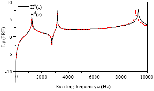 | |
| Fig. 2: | Curves of frequency response functions |
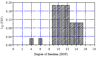 | |
| Fig. 3: | Degree of freedom identification index of damages |
And that the unit 6, 7, 8, 9, 10, 11, 12, 13, 14, 15, 16, 17, 18 may be damaged. Therefore, further step is needed to precise orientation.
Quantitative analysis: The value [β] can be obtained based on Eq. 22 and the damage degree of each unit can be got by Eq. 27, so as to achieve the accurate orientation and quantitative damage structure, shown in Fig. 4. From the result, it can be seen that the damage unit has some influence on the peripheral unit, but it’s not obvious. By and large, the accuracy of quantifying damage is acceptable.
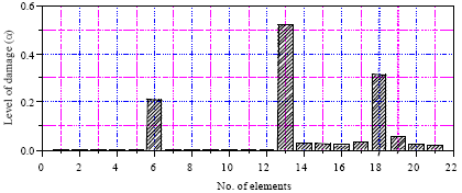 | |
| Fig. 4: | Results of elements damage identification |
The reason for the peripheral unit suffering damage interference is main from two aspects: (1) When using the least square method, the matrix is singular matrix and then making LU decomposition on it causes that the calculation result has a certain deviation. (2) The damage of some unit have a certain influence on the integrated state of the structure, thus it will be shown in the damage result.
The example shows that the identification results have a certain deviation, but the results are within the margin of error and have a good practicality.
CONCLUSION
The simulation results show that: First of all, the figure of acceleration frequency response function of the structure have obvious deviation before and after damage, which indicates that the figure has the obviously qualitative effect; secondly, through the introduction of structural damage index ζ, preliminary orientation can be done to the structural damage. The result shows that it makes accurate orientation to the damage unit, but can’t exclude the damage probability of peripheral unit. So, accurate damage unit can be obtained by the damage quantitative formula. Considering that the data of acceleration frequency response function is easy to obtain and its sensitivity, this method has a certain practical significance.
REFERENCES
- Yang, Z. and Z. Yu, 2004. Progress of damage detection for structural health monitoring. Adv. Mech., 34: 215-223.
Direct Link - Sohn, H. and C.R. Farrar, 2001. Damage diagnosis using time series analysis of vibration signals. Smart Mater. Struct., 10: 446-451.
CrossRef - Rytter, A., M. Krawczuk and P.H. Kirkegaard, 2000. Experimental and numerical study of damaged cantilever. J. Eng. Mech., 126: 60-65.
CrossRefDirect Link - Chiu, W.K., S.C. Galea, L.L. Koss and N. Rajic, 2000. Damage detection in bonded repairs using piezoceramics. Smart Mater. Struct., 9: 466-475.
CrossRefDirect Link - Guo, H.Y. and Z.L. Li, 2007. Qualitative and quantitative identification of multiple damages based on incomplete frequency response functions Eng. Mech., 24: 13-17.
Direct Link - Lee, U. and J. Shin, 2002. A frequency response function-based structural damage identification method. Comput. Struct., 80: 117-132.
CrossRefDirect Link - Greco, A. and A. Santin, 2002. Comparative study on dynamic analyses of non-classically damped linear systems. Struct. Eng. Mech., 14: 679-698.
Direct Link - Shi, Z., S. Law and L. Zhang, 2000. Optimum sensor placement for structuraldamage detection. ASCE J. Eng. Mech., 126: 1173-1179.
CrossRef