
S. Dharanya
M. Tech, Embedded Systems School of Computing, SASTRA University, Thanjavur, Tamil Nadu, India
M. Priyanka
M. Tech, Embedded Systems School of Computing, SASTRA University, Thanjavur, Tamil Nadu, India
R. Rubini
M. Tech, Embedded Systems School of Computing, SASTRA University, Thanjavur, Tamil Nadu, India
A. Umamakeswari
Associate Dean, School of Computing, SASTRA University, Thanjavur, Tamil Nadu, India
Journal of Artificial Intelligence
Year: 2013 | Volume: 6 | Issue: 1 | Page No.: 33-42


ABSTRACT
Transformers are basic design of electrical device which provide power transmission by transforming induced current from one circuit to another. The induced current can be converted step up or step down of current or voltage. This application mainly concentrates on the three-phase transformers which are used in between electric poles and the Power transformers. The real time controlling is done on the basic features like gas level, oil aging and regulation of overload and temperature maintenance. These features are essential for effective power transmission and long life of industrial transformers. The monitoring and control of the transformer is done by using ARM7 processor, RF transmission for wireless communication and sensors which check the level of gas, aging of oil, overload and maintain temperature by regular observation. There are various transformer maintenance techniques but this paper gives a real time monitoring and controlling of transformers by using ARM7 processor which replace the bulky computers making it as embedded system. The design is to sense the features of transformer and send the information regularly to the processor, the processor in turn will makes the transmission through RF to the client. So, this design makes possible to attain real time control and monitoring of oil, gas, overload and temperature range in the transformer.
PDF Abstract XML References Citation
Received: October 17, 2012;
Accepted: December 26, 2012;
Published: January 14, 2013
How to cite this article
S. Dharanya, M. Priyanka, R. Rubini and A. Umamakeswari, 2013. Real Time Monitoring and Controlling Of Transformers. Journal of Artificial Intelligence, 6: 33-42.
DOI: 10.3923/jai.2013.33.42
URL: https://scialert.net/abstract/?doi=jai.2013.33.42
DOI: 10.3923/jai.2013.33.42
URL: https://scialert.net/abstract/?doi=jai.2013.33.42
INTRODUCTION
In Electrical power transmission systems, transformers represent one of the key components in utility systems. Since, it is an integral part of the substation, strategic bottle necks occur if we fail to monitor the transformer (Bashi, 2005). Regular monitoring of the crucial roles of a transformer before causing ruining the system due to arising faults (Haron et al., 2012). This can allow for a change from periodic to condition-based maintenance. Some parameters of the transformer operation are (1) Temperature of oil, (2) Moisture level, (3) Level of floats, (4) Operation of cooling fans, (5) Electrical load levels and (6) Gas sensors (Bashi et al., 2007). This study shows the Real time Monitoring and control of systems using sensors for reading the value of different parameters of transformers.
The reason for using ARM7 processor devices are cost effectiveness, small size, robust and reduced power consumption which helps in the use of minimum power. So the basic features of ARM can be used for an industrial application like controlling of Transformers in a real time. The RF communication needs a base band processor which will provide a wireless mode of communication between a monitoring embedded device and the client by instant messaging about transformers features in regular intervals.
So, the combination of ARM7 processor and the RF communication provides with best performance, compatibility of sensors and security. The life of a transformer also plays an important role, as extended life of a transformer may in turn cut costs.
For monitoring transformers many methods have been adopted (Maizana,2012). In earlier works Oil level, float level, Temperature level, overload has been measured manually (Abaci et al., 2007; Zhao et al., 2004). These levels should be checked periodically by the operating personnel which will be tedious and inefficient way of monitoring. For better monitoring of transformers several works like, Transformer controlled with a microcontroller and sending data through serial communication to a host computer has been implemented (Sun et al., 2011; Sudha and Anbalagan, 2009). Also, several electrical transformers are allowed to communicate with host computer within a closed network (Devidas and Ramesh, 2010). Other works include capacitor sensor which can sense the di-electric signals for detecting moisture level inside transformer pressboard (Li and Gao, 2009).
Monitoring of distribution transformer using GPRS communication provides an effective monitoring making use of wireless communication and broadband transmission (Mao, 2010). The online monitoring of transformer features and controlling of transformers from a remote region using web service technology (Leger et al., 2001; Shertukde and Shertukde, 2002; Ahmad and Rashid, 2007). The analysis of gases dissolved in transformer oil is made through semiconductor sensor array (Cao et al., 2008; Severo et al., 2010; Moghaddam et al., 2012).
Thus, the earlier works shows various protection measurements of transformers and power supply but all those systems lack in providing a robust and sophisticated embedded system which can maintain transformers in real time and improve the transformers life (Kouzou et al., 2010; Bashi et al., 2008; Ahmad, 2010).
TRANSFORMER
The block diagram shown in Fig. 1 depicts the hardware configuration of the complete system. General faults in a transformer can be grouped as: (1) Mechanical, (2) Contacts erosion and (3) Contact coking leading to high resistance and overheating. In order to reduce some internal failures like risk of fire and explosions, several standards and protective devices have been installed. There are several parameters which will affect the working of the transformer. The four main parameters that are mainly concerned here are gas, temperature, overload and oil.
The centre ARM7 processor handles the monitoring and controlling process of transformer along with transmission. ARM processors are a 32-bit embedded processor. It can even support thumb instruction set. It has a RISC architecture which uses load and store properties. It executes instructions in fixed width and efficient in ease of decoding and pipelining by the use of thumb instructions. The execution of an instruction will have high code density and ARM executes instruction as single bit. It supports all the operating systems depending upon the applications and the web browsing performance using ARM processor is same as any other advanced processor like Intel atom processor. All this features of ARM will give best performance to develop leading edge technology in a broad range of applications like mobiles, networking, consumer, industrial automation. If any discrepancies occur it will identify, control that and inform it to the user through wireless transmission.
Inside a transformer formation of many gases takes place. They are listed as: Atmospheric gases: Hydrogen, Oxygen, Nitrogen; Oxides of carbon: Carbon monoxide and carbon dioxide; Hydro carbons: Acetylene, methane, ethane.
 | |
| Fig. 1: | Block diagram of the entire system |
Formation of gas inside the transformer is a major problem which is formed due to decomposition of oil, insulation overheating, corona, arcing of the transformer, etc; all this change of information will be continuously sensed by the gas sensor and sent to the processor and this will be intimated to the operator by parallely switching on the exhaust fan.
In larger transformers part of the design problem is the removal of heat. If under any circumstances temperature rises above the desired level which in turn will affect the transformer working condition. The processor will indicates this temperature rise to the receiver and eventually control the process by switching on the cooling fan.
Overload on the transformer will automatically cause the transformer to shut down, instead if the processor detects overload condition from voltage divider, will send the information to the receiver and shares the load to another transformer along with an indication through an alarm. The transformer oil acts as a lubricant, coolant, as well as insulator for the windings. To check the oil aging here the Conductivity test (Resistivity test) is performed. The process uses two electrodes; the conductivity between these two is inversely proportional to the oil thickness. High resistivity shows the fewer amounts of free ions and conductive contaminants. If the processor detects the current flow then it will send the information to the user through wireless communication.
The gas sensor used in measuring the gas detection process is developed by NSK electronics products. The sensor detects the different gases by varying the resistance of all gases produced in an industry. The graph above Fig. 2 shows the resistance range versus pressure of gas. We can see that Hydrogen gas exists in centre of the graph. Every gas sensor will detect the presence of a gas by its varying resistance. This is directly proportional to the output showing gas detection by its pressure.
The temperature sensor used is LM 35 shown in Fig. 3. The sensor has three pins, Vi is the input voltage pin which acts at 5V, Vo is the output voltage gives the display provided to it. GND pin is the ground pin.
 | |
| Fig. 2: | Graph shows the resistance ratio versus pressure of the gases, Rs/Ro: Resistance range |
 | |
| Fig. 3: | The temperature sensor LM 35 pin diagram |
The output voltage is directly proportional to the varying resistance. If temperature rises above the desired level, cooling fan will be automatically switch ON. This reduces the raised temperature of the transformer. Generally, by using ARM7 processor the use of cooling Fan inside the industrial transformers is greatly reduced. The output of Temperature sensor is displayed in LCD display showing the detected temperature value. The Flow chart for the entire process is explained as shown in Fig. 4.
Algorithm:
| Step 1: | Initially sensors will sense the transformer conditions |
| Step 2: | The sensed information is sent to ARM7 processor |
| Step 3: | Depending on the sensed information processor will send respective signals to the Peripherals to act |
| Step 4: | The sensed data is sent to the operator by processor |
RESULTS AND DISCUSSION
The experiment is performed by considering the two parameters of a Transformer like gas detection and temperature range. The general ranges of transformer values are executed and sent to the RF receiver from RF transmitter.
 | |
| Fig. 4: | Flow chart shows the step by step process |
 | |
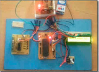
| Fig. 5: | Snapshot of ARM 7 LPC 2148 board |
The Fig. 5 shows the snapshot of LPC 2148 board where all the peripherals will be interfaced in it. It is interfaced with temperature sensor LM35, Gas sensor, etc., for sensing temperature and gas detected in the surroundings, along with cooling fan to reduce the heat inside the transformer and an exhaust fan to expel the gases outside the transformer, respectively. Figure 6-8 shows the snapshots of transmission unit.
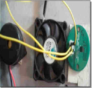 | |
| Fig. 6: | Module of temperature sensor with exhaust fan and alarm unit |
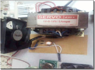 | |
| Fig. 7: | Transformer (12v-5 A range) with cooling fan |
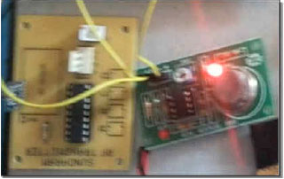 | |
| Fig. 8: | RF transmitter module along with gas sensor |
The Fig. 9 shows the receiver unit for RF transmission. The RF receiver is connected to the microcontroller for displaying the output in the LCD. The RF transmission process is visualized by simple 16x2 LCD display as shown in Fig. 10. The stimulation output is shown in Fig. 11. The emulation output is also shown in Fig. 12 and 13 using ISIS Emulator.
 | |
| Fig. 9: | Receiver module of RF transmission |
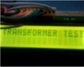 | |
| Fig. 10: | LCD display of test performed for transformer parameters |
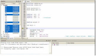 | |
| Fig. 11: | KEIL stimulator snap shot shows the debugging unit |
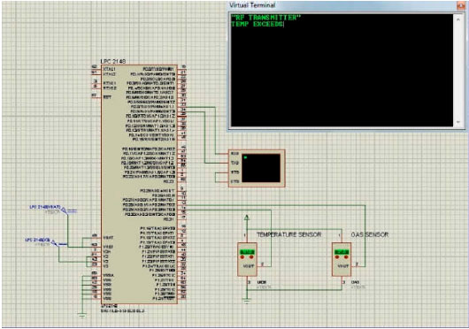 | |
| Fig. 12: | Snap shot of ISIS emulator indicating the transmission of “rise in temperature” to the receiver |
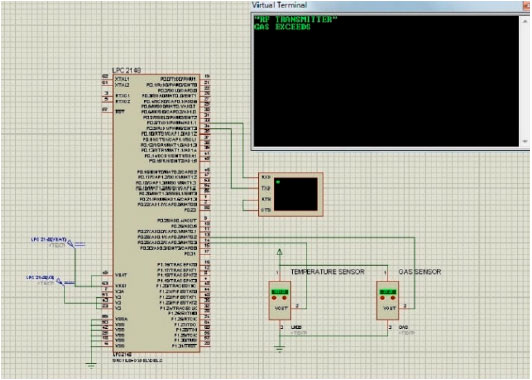 | |
| Fig. 13: | Snap shot of ISIS emulator indicating the transmission of “rise in gas level” to the receiver |
CONCLUSION AND FUTURE WORK
This study gives remedies from the faults occurring in transformer and it overcomes the drawbacks of previous working methods. The paper focuses much on the efficiency of controlling process of the transformer and mainly through wireless communication that eliminates the use of large cables which are of high cost, low reliability and maintenance.
The RF Transmission helps in better way of communication which enhances the improvement steps in this process.
So, use of ARM processor makes the system real time embedded system and aids very much in industry needs. This work can also be extended to handle several numbers of transformers on industrial units by assigning RFID tags to each transformer which in turn is monitored and controlled by a single ARM processor.
REFERENCES
- Ahmad, D.M.M., 2010. Evaluation of the localized loss transformer core lamination. J. Applied Sci., 10: 2917-2922.
CrossRef - Haron, A.R., A. Mohamed and H. Shareef, 2012. A review on protection schemes and coordination techniques in microgrid system. J. Applied Sci., 12: 101-112.
CrossRefDirect Link - Bashi, S.M., N. Mariun, N.F. Mailah and S. Alhalali, 2008. Low harmonics single phase multilevel power inverter. Asian J. Sci. Res., 1: 274-280.
CrossRefDirect Link - Bashi, S.M., N. Mariun and A. Rafa, 2007. Power transformer protection using microcontroller-based relay. J. Applied Sci., 7: 1602-1607.
CrossRefDirect Link - Bashi, S.M., 2005. Microcontroller-based fast on-load semiconductor tap changer for small power transformer. J. Applied Sci., 5: 999-1003.
CrossRefDirect Link - Moghaddam, G., M. Amiri and J. Khodaei, 2012. Fuel energy saving and environmental benefits from a combined heat, cooling and power system driven by gas engine. Asian J. Applied Sci., 5: 266-278.
CrossRefDirect Link - Ahmad, I. and A. Rashid, 2007. On-line monitoring of hydropower plants in Pakistan. Inform. Technol. J., 6: 919-923.
CrossRefDirect Link - Abaci, K., Y. Uyaroglu, M. Ali Yalcin and M. Yildiz, 2007. Observing chaotic oscillations induced by under load tap changer in power systems. J. Applied Sci., 7: 66-71.
CrossRefDirect Link - Kouzou, A., M.O. Mahmoudi and M.S. Boucherit, 2010. Apparent power ratio of the shunt active power filter under balanced power system voltages. Asian J. Applied Sci., 3: 363-382.
CrossRefDirect Link - Sudha, M. and P. Anbalagan, 2009. A protection scheme for three-phase induction motor from incipient faults using embedded controller. Asian J. Scientific Res., 2: 28-50.
CrossRefDirect Link - Li, W. and C. Gao, 2009. Mechanisms and testing of moisture content measurement of transformer pressboard. Proceedings of the 9th International Conference on Electronic Measurement and Instruments, August 16-19, 2009, Beijing, China, pp: 352-356.
CrossRef
mukeshkumar.s Reply
sir i need this circuit diagram with component specification for implementing part of our project. plz do me a favor.
pol Ganesh Reply
I m last year BE electrical engineering students
Plz give us circuit diagrams and other information regarding this sub we decide to work on this sub as project....
nebe desmond Reply
greetings sir, i am working on automatic parameters conctrol on transformer like overload, gas level, oil level and temperature using an arduino microcontrol and i will like to have a circuit diagram for the practical implemmentation.
Simeon Reply
Greetings sir,
Please am working on this very project, please help and assist me with the full material and other guide u feel will help me. Am a final year student in Nigeria. Please help me Sir
Editor
Dear Simeon,
Thank you for showing interest in the research article on Real Time Monitoring and Controlling of Transformers. We are glad to know that you are working on a similar project and would like to seek our assistance.
We suggest that you carefully go through our research article and related literature to gain insights and ideas. Additionally, we encourage you to seek guidance from your supervisor or mentor as they can provide you with the necessary assistance and direction.