
Bin Zhuge
Huanhuan Song
Cheng Yu
Wei-ming Wang
Information Technology Journal
Year: 2012 | Volume: 11 | Issue: 7 | Page No.: 816-828


ABSTRACT
The communication bottleneck between Control Elements (CEs) and Forwarding Elements (FEs) of ForCES router is the critical factor that restricts its large-scale application. In view of this problem, this study is about the communication efficiency and transmission performance of Transport Mapping Layer (TML) based on SCTP. It analyzes the coordination mechanism of channel flows among FEs. This study puts forward a complete flow control mechanism in internal channel of ForCES router and improves the communication efficiency. Furthermore, according to the distributive rate, the dispersion count and the flow rate of task, this study analyzes the performance of model. It shows that the flow control mechanism this study suggests can effectively guarantee throughput and reliability of communication between CEs and FEs. At last, this study verifies the accuracy of the theory through ns-2.34 simulation experiments.
PDF Abstract XML References Citation
Received: November 15, 2011;
Accepted: March 27, 2012;
Published: May 29, 2012
How to cite this article
Bin Zhuge, Huanhuan Song, Cheng Yu and Wei-ming Wang, 2012. Research on SCTP-Based TML for ForCES Routers. Information Technology Journal, 11: 816-828.
DOI: 10.3923/itj.2012.816.828
URL: https://scialert.net/abstract/?doi=itj.2012.816.828
DOI: 10.3923/itj.2012.816.828
URL: https://scialert.net/abstract/?doi=itj.2012.816.828
INTRODUCTION
The increasing Internet scale puts forward higher requirements to processing power, message transmission performance and physical interface support density of the network equipment. With the development trend of technology, the products of the next generation network had increasingly become modular, distributed, open and programmable (Fu, 2008). The new network architecture realized the modularization of network elements and open and unified interfaces were taken in the communication among the modules (Abed et al., 2011). The new architecture could improve the scalability, flexibility and effectiveness (Fu, 2008). Forwarding and Control Element Separation (ForCES) of IETF with the above characteristics was the new generation network architecture (Doria et al., 2010). The ForCES protocol which divides network elements into control elements and forwarding elements is used to achieve the cooperation and interaction among components. Thereby the scalability and manageability of network system were increased and the scalability and flexibility of network were enhanced (Takourout et al., 2006; Fu, 2008).
In early 2004, General Router Management Protocol (GRMP) (Wang and Dong, 2004), Forwarding and Control Element protocol (FACT) (Audu et al., 2003) and Netlink2 (Salim et al., 2003) of candidate protocols were amalgamated into single one by the ForCES working group and it was ForCES protocol (Fu, 2008; Khosravi and Anderson, 2003; Yang et al., 2004). The ForCES working group respectively completed the ForCES requirements document (RFC 3654) and frame document (RFC 3746) in 2003 and 2004. Since then, the research had focused on the ForCES protocol (Halpern, 2005), FE model, LFB definition Library, ForCES TML, ForCES MIB and the design of standard draft document. In early 2010, four core drafts of the ForCES working group became RFC. It promoted manufacturers and scholars to have more intensive study on the architecture of ForCES network (Audu et al., 2003; Halpern and Ma, 2007).
This study studies the flow control technology of the internal channels of ForCES router which is mainly based on the ForCES Transport Mapping Layer (TML). TML was important component of ForCES architecture network (Wang et al., 2004) and also the key in restricting communication performance of the entire system. TML separates the protocol layer from the bottom layer of network. That solves the transmission problems of ForCES protocol messages in different link layers (such as, TCP/IP, ATM, Ethernet layer, backboard bus and so on). Thus, it provided a transparent, safe transmission channel for the ForCES protocol layer and improved the flexibility of ForCES system (Feng et al., 1999; Aweya, 2001).
More and more units joined the ForCES team at home and abroad, because ForCES protocols officially became RFC international standards. The present study was based on the function of ForCES network elements and the theory study on TML of ForCES network was relatively weak (Ogawa et al., 2011; Dong et al., 2011). This study is mainly about theoretical analysis and algorithm research on realization of some critical technologies of ForCES TML, certificated by software simulation and system experiment. The results will effectively promote the application development of protocol in ForCES TML and will make a solid foundation for the application of network element (Crouch et al., 2010; Zhuge et al., 2011; Mohammadi et al., 2009).
STRUCTURE OVERVIEW FOR FORCES TML COMMUNICATION MODEL
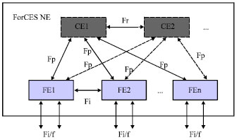
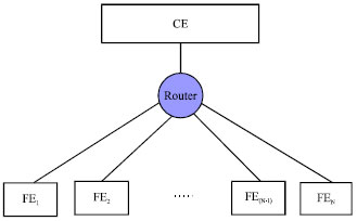
ForCES TML communication model structure is the foundation to research the flow control technology in internal channels of ForCES router. The performance of communication model is directly related to the properties of the entire ForCES router. The separation of forwarding elements and control elements was the core of ForCES architecture router. RFC 3746 (Yang et al., 2004), the ForCES framework document, defined the basic structure of a standard ForCES architecture network as Fig. 1 (Zhang et al., 2009; Ibrahim, 2008).
In the ForCES architecture network, there is one or more CEs, they are main control CE and redundant CEs. Redundant CEs are mainly used to achieve the high availability of system. There can be many FEs in the network element and all of them are separated from the CEs. The interface between CE and FE is standardized, and the messages interaction conforms to ForCES protocol. The ForCES network element looks like a network node upon the exterior. As to the external entity, the network element hides the internal structure, equivalent to a router or switch. In Fig. 1, Fi/f is external interface of FE, Fl is interface between CE manager and FE manager. Ff is interface between FE manager and FE, Fc is interface between CE manager and CE, Fr is interface between CE and CE. Fi is interface between FE and FE, Fp is interface between CE and FE, the communication standard of Fp is the core research content of ForCES protocol (Zhuge et al., 2011).
In ForCES router, the transmission of protocol messages between CE and FE is the key in restricting the communication performance of the whole communication system. Therefore, the choice of transport protocols is related to the performance of the whole system. In RFC 5811, SCTP has been defined as the transport protocol of TML. SCTP has most of the required characteristics to construct a robust TML, support a simpler coding and reduce many problems such as interoperability. So, the next research and implementation of this study is based on SCTP network.
 | |
| Fig. 1: | Architecture of ForCES Network |
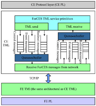
ForCES architecture included two parts, Protocol Layer (PL) and TML (Doria et al., 2010). PL is responsible for generating ForCES protocol messages independent of the type of TML. At the same time, PL manages and controls TML. TML is responsible for the transmission of PL messages and TML shields transmission medium component when messages are transmitted. It provides a transparent and safe message transmission channel for PL. TML underlies under PL, TML includes CE TML of control plane and FE TML of data plane. The communication between CE PL and FE PL is realized by CE TML and FE TML. When there are messages to be transmitted, PL will send ForCES messages to TML of itself. Then to realize the transmission of ForCES messages between two PL entities through the message exchange between two TMLs.
The CE TML router will communicate with multiple or even hundreds of FE TMLs at the same time in ForCES framework router. This is a typical one-to-many communication mode. Therefore, the implementation of TML communication mainly adopts server/client mode, namely take CE TML as a server, FE TMLs as the clients. FE TML issues a task request to CE TML and they establish a connection and take communication processing. In this mode, CE TML chooses the communication mechanism to realize and coordinate the communication flow and it is the key research (Qaddoura et al., 2002).
BANDWIDTH ALLOCATION IN FORCES TML
In ForCES router, the TML is responsible for the transmission of ForCES protocol messages in SCTP transmission medium. In order to transmit various protocol messages efficiently, TML need take proper bandwidth allocation for each sub channel in ForCES channels. As what showed in Fig. 2, based on TCP/IP network, ForCES TML provides services for protocol layer. ForCES TML is also responsible for the transmission of ForCES protocol messages between protocol layers.
 | |
| Fig. 2: | Architecture of TML |
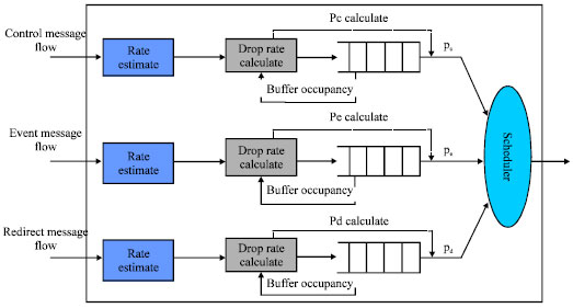
ForCES protocol layer will produce three types of ForCES protocol messages, control protocol messages, event protocol messages and redirection protocol messages. And, control protocol messages are generated by FEs or CEs for control information exchange. Such as the protocol messages for configuring or querying the parameters of FEs or CEs. The normal transmission of control protocol messages is the necessary condition for the normal work of the whole router. Event protocol messages are generated when the event registered in the event dispatch module happens. Such as, control channel messages arrival event, event channel messages arrival event, redirect channel messages arrival event, listening socket connection events. And messages will be generated when these events occurs. These types of event messages can be cumulated and CE can get the event message through sending a query to FE. So, this event message can tolerate loss. Redirect protocol messages are used to load the data packets. For example, FEs need redirect network packets which come from the network via the network interface, to CEs. CEs also need send a number of data packets which are generated by these CEs, to FEs. Then FEs send these packets to the exterior of the network. And the data is transmitted by the redirect protocol messages of ForCES protocol. Therefore, the ForCES TML must ensure the transmission of control protocol messages. To transmit event protocol messages and redirect protocol messages effectively without affecting the transmission of control protocol messages (Haleplidis et al., 2010; Stoica et al., 2003; Sharma et al., 2007).
The focus of traditional bandwidth allocation algorithm is to improve distribution efficiency, and pay little attention to message attributes and the importance of different messages. So, it lacks pertinence and encounters a bottleneck in improving utilization rate of cybersource. According to different characteristics of different message flows in ForCES router, this study puts forward a new bandwidth allocation mechanism. It is rte and buffer based active queue management-dynamic probabilistic priority scheduling in ForCES channel.
Summarize of RBAQM-DPP algorithm: RBAQM-DPP algorithm model is shown in Fig. 3. In this algorithm, firstly, set up a FIFO queue, respectively for the control messages, the event messages and the redirect messages. At the same time, set the initial scheduling probability for the control message queue, the event message queue and the redirect message queue. Note the probabilities as pc, pe, pd, the sum of the three probabilities is 1. Then, set Minthd as the minimum buffer threshold of queue and set Maxthd as the maximum buffer threshold of queue for each message queue, respectively. Affect the allocation of link bandwidth resource by adjusting the queue scheduling probability.
In the module of priority scheduling in probability, according to values of pc, pe, pd, to schedule forwarding packets from the head of each message queue. Obviously, in the event that the total link bandwidth is fixed, if pc increases, the corresponding bandwidth of control channel will increase. It will lead to diminished occupied bandwidth of the event channel and redirect channel. In RBAQM-DPP, the value variability of Minthd and Maxthd provides more initiative and plasticity for the algorithm. In different stages of the transmission, administrators can better meet the transmission requirement of all types of messages by setting different values of Minthd and Maxthd. So, as to further improve the quality of transmission (Guo, 2001).
Realization of RBAQM-DPP algorithm: The algorithm consists of two techniques, active queue management and queue scheduling. Queue scheduling mainly realizes the rational distribution on link bandwidth resource through the scheduling mechanism, so as to ensure the reserved bandwidth strictly. Active queue management adopts some strategy to decide whether to discard the message packet according to feedback information of queue in the arrival of packet (Athuraliya et al., 2001; Jasem et al., 2010; Kunniyur and Srikant, 2000).
 | |
| Fig. 3: | RBAQM-DPP Scheduling model |
Queue scheduling: When the algorithm executes, firstly, according to the initial values of scheduling probability, to schedule and forward the message packets of each channel. In the service of each round, the probability of scheduling and forwarding control messages is pc. The probability of scheduling and forwarding event messages is pe. And the probability of scheduling and forwarding redirect messages is pd. Thus, the occupied bandwidth of three message channels is:
| (1) |
where, B is total link bandwidth between CE and FE communication. Bc, Be, Bd are, respectively the channel bandwidth of the control channel, the event channel and the redirect channel.
Active queue management: In the transmission process of news groups, usually to improve the utilization of network bandwidth by taking queue cache (Matsurfum and Aibara, 1999). Active queue management is important means to realize the control of network congestion. It influences the link bandwidth allocation through the control on buffer resource. On a single network node, its control goal is to improve the throughput and allocate bandwidth resources reasonably at the same time (Bennett and Zhang, 1996; Hollot et al., 2001).
Firstly, to assign the limited bandwidth to three different message flows effectively through reasonably setting Minthd and Maxthd of each message queue. Therefore, when the message starts to lose packets with a probability, the determination of Minthd and Maxthd of this queue determines the lower and upper occupied bandwidth. To set values of Minthd and Maxthd of the queue by the characteristics observed from the three actual ForCES message flows and priority of the three kinds of messages (Bennett and Zhang, 1997; Floyd and Jacobson, 1993).
Then, when there is message going into the queue, first of all, obtain the buffer occupancy information of this kind of message queue. Compare the obtained results with the prior given threshold of queue length (Ott et al., 1999). When the message queue length exceeds Maxthd of the queue, it shows that the message channel has congestion phenomenon, then discard the message directly. When the message queue length is less than Maxthd, the enqueueing module will firstly calculate the packet loss probability pq-dp of current message. The loss probability pq-dp is caused by the changing queue length. Then, according to the average arrival rate of message flows in each channel, calculate packet loss coefficient pr-dp to determine whether to perform loss. Packet loss coefficient pr-dp is caused by the changing average arrival rate of the three kinds of message flows. That means that the total loss rate is:
| (2) |
Calculate pq-dp and pr-dp by the following method:
Through the above analysis, we know that when the message queue length exceeds Maxthd, discard the message directly, so, pq-dp = 1. When the message queue length is less than the minimum buffer threshold Minthd, it shows that the news channel has no congestion. And all the arrival messages are permitted to enter the current message queue, so pq-dp = 0. When the message queue length is between Maxthd and Minthd, calculate the packet loss rate of a new arrival message packets like Eq. 3:
| (3) |
In Eq. 3, a is a constant, l is the current message queue length, Minthd<l<Maxthd, t = Minthd. In current study, there are also a lot of methods using the linear increase, and at Maxthd, it reaches the maximum loss value. It can be said that this issue is still a relatively open problem. Solve the derivation on the left and right of Eq. 3:
| (4) |
In Eq. 4, the value of a determines the smoothing degree of the curve. In addition, with the increasing of queue length l, the increasing rate of packet loss rate increases. We can try to maintain the queue in a stable queue which receives burst message flows. Now, a lot of studies propose that the transition from discarding to discarding completely should tend to be smooth as soon as possible. Namely, when the queue length reaches Maxthd, the value of pq-dp is close to 1. Thus, once we determine the values of Maxthd and Minthd, the value of a is determined.
In short:
 | (5) |
According to average arrival rate r of message stream, the enqueue module determines packet loss coefficients pr-dp. Using tk and lk to express arrival time and length of the kth message packet, respectively. When a new message arrives, estimate the average arrival rate of the message stream using exponential average algorithm:
| (6) |
There, α = e Tk+1/K is index weight, rold is the average arrival rate of message flow before the arrival of the new message packet. Tk+1 = tk+1= tk , it shows the arrival interval between the (k+1)th message and the kth message, K is a constant.
The index weight α is a variable which is different from the index weight of constant, arrival interval time T of packets is a variable. The intent of using such a variable index weight is to reflect the average process of the message flow independent of the packet structure more accurately. More precisely, if the index weight is a constant, the estimated average rate of the arrival message flow is sensitive to the message packets length. And the estimated rate is different from real-time arrival rate because of some reason. Contrarily, using such an index weight of variable α, the estimated rate will asymptotically tend to be the real rate.
In the expression α = e Tk+1/K of α, give many tradeoffs to the value of K. Firstly, a smaller K can increase the response and produce rapid rate fluctuations, while a larger K can better avoid potential instability of the system. Secondly, delay jitter changes the arrival time interval of message packets. This will lead that the difference between the estimated rate and the real-time rate increases ceaselessly. In order to overcome this effect, according to the experience, the value of K and the delay of message flow should be in the same order of magnitude. In addition, the value of K can’t exceed the average duration of message flow. In view of the above constraints, a suitable value of K should be set between 100 and 500 msec. Known from the above, the average arrival rate of the current message flow is r. Note the average arrival rate of the current control messages as rc, the average arrival rate of the event messages as re, the average arrival rate of the redirect messages as rd. So the loss coefficient is:
| (7) |
| (8) |
Next, as to all the reaching news, we will adjust the value of scheduling probability of the kind of message according to the value of pdp and the message queue length. As to the control channel, note that the current queue length is lc, the total loss rate is pcdp. When the control message packet arrives, the packet loss rate of control message packet caused by the queue length is pcq-dp. Calculate the scheduling probability pc of control channel according to lc and pcdp, get from the Eq. 5:
| (9) |
 | (10) |
So, it can be pc:
| (11) |
And, β is the corresponding proportion coefficient caused by the queue length and the bandwidth, β is a fixed value.
As to the event channel, note that the current queue length is le, the total loss rate is pedp. When the event message packet arrives, the packet loss rate of event message packet caused by the queue length is peq-dp. Adjust the scheduling probability according to pc and pedp, adjustment process is as follows:
The occupied bandwidth of control channel is Bc, so the residual bandwidth is B-Bc, get from Eq. 5 similarly:
| (12) |
 | (13) |
Therefore, remove the bandwidth of control channel, the relative scheduling probability pe and p'd can be gotten from the remaining bandwidth B-Bc. And p'e is relative scheduling probability of the event channel, p'd is relative scheduling probability of the redirect channel. They are:
| (14) |
| (15) |
In the remaining bandwidth B-Bc, note that the relative surplus scheduling probability is Δp'c in addition to the event channel and the redirect channel:
| (16) |
Thus, it obtains:
| (17) |
| (18) |
To except the event channel and the redirect channel, the remaining scheduling probability Δpc by calculating is:
| (19) |
To obtain the final, pc is:
| (20) |
In the bandwidth B-Bc, if the sum of occupied bandwidth of the event channel and the redirect channel is less than B-Bc, allocate the residual bandwidth to control channel. And this will provide better protection for the transmission of control message.
Therefore, because of the RBAQM-DPP scheduling mechanism, TML can improve the utilization of network bandwidth. At the same time, it guarantees the transmission of control messages and avoids the starved phenomenon of the low priority channel. So it improves the communication performance of ForCES router fundamentally.
RESEARCH ON FLOW CONTROL MECHANISM BETWEEN FORCES CHANNELS
The research in the above section is in the case of a CE connected with a single FE. And it is the bandwidth allocation algorithm that among the three news channels of the ForCES channels. FE can occupy the full bandwidth of CE communication link naturally. But usually, in a ForCES router, one CE generally controls dozens or even hundreds of FEs, as shown in Fig. 4. When a CE connects with multiple FEs, the total bandwidth B allowed by CE communication will be assigned to more than one FE. That’s because it wants to take normal data interaction between the FEs and CE, especially to ensure the transmission of high priority messages in ForCES channels. When the sum of message rate in each ForCES channel is larger than the total bandwidth of CE communication, if we don't take any measures, it will inevitably cause congestion. It results in the message packets of each ForCES channel discarding randomly at the connection nodes of CE and FEs. In the case of severe congestion, it might even lead that the messages of a ForCES channel were discarded totally or the control messages were largely abandoned. This would ceaselessly increase the delay time of message transmission (Kanher and Sethu, 2001).
Obviously, good control of the ForCES channel flow is very important for the accurate and safe message interaction between CE and multiple FEs. This requires a more accurate prediction for the flow of each ForCES channel. And the most important is how to forecast the average arrival rate of ForCES channel messages in the next time. The forecasting precision will directly affect the accuracy of congestion judgment and whether the link bandwidth resources can be fully utilized.
 | |
| Fig. 4: | Simple ForCES router model |
The ForCES router has good expansibility. According to the extension mechanism of ForCES router, add flow control module in the CE end to achieve flow control mechanism. It is responsible for the over-all planning of flow control mechanism. Add a component in the FE end, abstract the flow control function resource, finish the query configuration channel which is provided for the top layer and achieve the function entity of flow control. The model of flow control mechanism is as shown in Fig. 5. Therefore, according to each ForCES channel, to design an algorithm called Prediction-based Flow Control and Configuration (PFCC) in the CE terminal.
Prediction-based flow control and configuration algorithm in ForCES channels: The core idea of PFCC algorithm is that, firstly, predict accurately the message flow of each ForCES channel in the next time. Then CE allocates available bandwidth for each ForCES channel instantaneously, to ensure message transmission quality and realize the reasonable allocation of cybersource at the same time.
Flow prediction of ForCES channels: In the ForCES router, there are a large number of observations about the changes of message flows in each channel. It can be found that, the message flows of each ForCES channel don’t show a strong long range correlation. Thus, using Minimum Mean Square Error (MMSE) to predict is more precise. And MMSE algorithm is simple, has a small amount of calculation which meets the demand of on-line prediction. Research shows that, MMSE algorithm has more accurate prediction for aggregation flows than the single flow. And the flow prediction for a ForCES channel includes three converged sub message flows, so the prediction effect is more ideal.
Next, describe how to use MMSE algorithm to predict the arrival rate of the next packet.
 | |
| Fig. 5: | Model of flow control mechanism |
Using {Xt} represent linear stochastic process of the sent packet rate in t time, the arriving packet rate in the next time represents by the linear combination of the sent packets:
| (21) |
There into, μ = (μ1, μ2,..., μp) is partial correlation coefficient, X = (Xt, Xt-1, ..., Xt-p+1), ε is estimation error, p is order number.
Note the estimated value of Xt+1 as ![]() , the estimated value of μ as
, the estimated value of μ as ![]() .
.
In order to make the criterion error of estimation rate the minimum, according to the MMSE algorithm that E[ε2] takes the minimum value, namely solve the minimum value of:
Make:
thus, it obtains:
 | (22) |
And,
Thus, the rate of the arriving packet message in the next time can be written as:
| (23) |
Thus, for a single ForCES channel, using the index average algorithm to calculate the average rate of the channel message when the next packet arrives:
| (24) |
And, rkold is the average transmission rate of messages in the current ForCES channel. And rknew is the average transmission rate of messages in the ForCES channel when the number t+1 packet arrived.
Overview of PFCC algorithm: When the algorithm executes, firstly set the initial bandwidth Bkini for the corresponding ForCES channel of each FE which is connected with CE. The allocation bandwidth is Bkcon, the minimum bandwidth is Bmin and the maximum bandwidth is Bmax. There into, Bkini is the initial allocation bandwidth for the kth FE (ForCES channel), Bkcon is the allocation bandwidth for the kth ForCES channel. CE gets N which is the number of FEs connected with it every certain period and the current message transmission rate rk of each ForCES channel. Because there will be new FE to establish a connection with CE or the established connection disconnects, so N is real-time changing. In addition, actual occupied bandwidth values of ForCES channel may real-time vary with the arrival rate of the message flow. The algorithm adjusts allocation bandwidth Bkcon of each ForCES channel according to the change of N and the current actual occupied bandwidth values Bkrel of ForCES channel.
However, in PFCC, through reasonable adjustment of allocated bandwidth Bkcon for ForCES channel, the total allocated bandwidth of channels should be within the allowed bandwidth of CE communication. Thus it can avoid congestion. For a single ForCES channel, once the allocated bandwidth Bkcon is determined. The premise is that the total bandwidth of all the sub-channels of the single channel is within Bkcon. We can achieve this in accordance with RBAQM-DPP algorithm and make sure that the end-to-end delay of various messages is under control.
The realization of PFCC algorithm: Firstly, the same initial bandwidth Bkini should be allocated for the ForCES channel of each FE which is based on the quantity N of FE connected to CE. The method to calculate Bkini is as follows:
| (25) |
And pt is the probability that N FEs have message interaction with CE at the same time. At any time, the probability that each FE has message transmission with CE is γ and each FE is independent with others. So, the probability that N FEs have message transmission with CE at the same time is pt = γN. That is:
| (26) |
So, the initial bandwidth of each FE can be expressed as:
 | (27) |
Suppose that Bmax = Bkini A θ, Bmin = b, where 0<θ<1 and b>0 which is a constant. We can adjust the values of θ and b according to the actual situation. The allocated bandwidth Bkcon is initialized as Bmax.
Then, the value of Bkcon is adjusted according to the current bandwidth Bk of ForCES channel and the average arrival rate of messages in ForCES channel in the next moment. And the value of Brel is:
| (28) |
Then, the total spare bandwidth ΔB at present is:
| (29) |
Next, we can get the average rate of messages in ForCES channel when the next package arrives to re-determine the allocated bandwidth.
In the last section, when the (t+1)th package arrives, the average arrival rate is:
| (30) |
Thus, when the (t+1)th package is sent, the sum of average rate of messages in each ForCES channel is:
| (31) |
If rkt+1 = 0, then Bkcon = Bmin. The reason why the allocated bandwidth isn’t set to zero when there is no message to transmit is because of the burst stream. So, we can transmit data before the bandwidth is allocated and improving the transport efficiency of burst data stream.
If rkt+1 >0:
| (32) |
Now, the allocated bandwidth for each FE is:
 | (33) |
That is, the total spare bandwidth is allocated to each FE according to the proportion of message transmission rates.
If rkcon>Bmax, then set Bkcon = Bmax, so that, Bkcon will not be so large. The aim is that even if the channel is subjected from malicious attacks, for the entire network bandwidth B, the bandwidth expense is within Bmax. So it won’t cause congestion of the entire network. In conclusion, in PFCC, a reasonable bandwidth allocation for each ForCES channel can help users to avoid congestion. And it also can offer a reliable guarantee for end-to-end delay.
THE SIMULATION AND TEST
Simulation and test of RBAQM-DPP algorithm: Use NS2 network simulator to simulate the work of FE and CE in ForCES framework router under SCTP networks. To choose different news source models and strict probability priority scheduling algorithm (SP) recommended by RFC5812. Then compare and verify the performance of RBAQM-DPP algorithm proposed by this study.
The network simulation topology which is built in test is as Fig. 6, CE (node 0) and FE (node 2) are connected via a router (node 1). Three sources (node 3, 4, 5) are, respectively used to simulate the actual control messages, event messages and redirect messages.
 | |
| Fig. 6: | Topology of network simulation |
Message queue management and scheduling between FE and the router respectively use RBAQM-DPP and SP algorithm. In the CE terminal, to receive and analyze the transmission efficiency of each kind of information forwarded from FE.
In the test, the link bandwidth is as what showed in Fig. 6, set the link delay to 0.1 msec, the queue length to 100, K = 300 msec.
| • | Each message source sends messages at a constant rate, set the control messages in high priority channel (HP) at the rate of 4 Mb sec-1. Set the event messages in middle priority channel (MP)at the rate of 3 Mb sec-1, the redirect messages in low priority channel (LP) at the rate of 2 Mb sec-1, set the sampling time to 0.05 sec |
By the two Fig. 7 and 8 when each source rate is less than the link bandwidth 10 Mb. RBAQM-DPP, SP, the control messages, the event messages and the redirect messages all have normal transmission. RBAQM-DPP and SP algorithm essentially have the same effect.
| • | Set that the source model is that rate increases with time, the sampling time is 0.05 sec. To observe the performance of RBAQM-DPP and SP algorithm when there is congestion |
From the Fig. 9 and 10 it can be seen that, when the news source rate is small, three kinds of message flows in RBAQM-DPP and SP don’t have packet loss. However, as the news source rate increasing and congestion happening, the event messages and the redirect messages in SP are in severe packet loss phenomenon. Redirect channel is even in starved phenomenon. While in the action of RBAQM-DPP, even congestion happens, the event messages and the redirect messages can still maintain a certain transmission rate. It won't be in starved phenomenon in low priority channel.
 | |
| Fig. 7: | Performance of RBAQM-DPP without congestion |
 | |
| Fig. 8: | Performance of SP without congestion |
 | |
| Fig. 9: | Performance of RBAQM-DPP in Congestion |
 | |
| Fig. 10: | Performance of SP in congestion |
| • | In RBAQM-DPP, through taking different values of Maxthd and Minthd, to observe the output bandwidth of each message stream, sampling time is 0.5 sec. In order to better reflect the test results, set the output of each message source at a constant rate. Set the rate of the control messages at 8 Mb sec-1, the rate of the event messages at 3 Mb sec-1, the rate of the redirect messages at 4 Mb sec-1 |
Such as shown in the Fig. 11 and 12, different values of Maxthd and Minthd, the output bandwidth ratio of each message channel has a more obvious change. To increase the values of Maxthd and Minthd, the output bandwidth of control channel is increased. When Minthd = 30, Maxthd = 75, the output bandwidth of the control channel nearly reaches the input rate 8 Mb sec-1 of the control message. To reduce the values of Maxthd and Minthd, the output bandwidth of the control channel is decreased. But the output bandwidth of the event channel and the redirect channel increases. This characteristic of RBAQM-DPP provides more workable space for network administrators. According to the change of different message flows number in each stage, the administrator can dynamically adjust the value of the queue length threshold. For example, at the beginning of establishing a connection, the control messages in message stream apparently accounts for the major part. So, the maximum threshold and the minimum threshold should be relatively set to large values. But once connects, the control messages proportion in message flow accounts for only a small part, the main part is redirect messages data. So, the maximum and minimum threshold should be relatively set to small values, so as to improve the communication performance of the whole system.
 | |
| Fig. 11: | Minthd = 20, Maxthd = 50 |
 | |
| Fig. 12: | Minthd = 30, Maxthd = 75 |
Test and Analysis of Multi-FE Flow control algorithm: In the NS2 network simulation tool, to set up network simulation environment as shown in Fig. 13, messages of FE-1 (node 2), FE-2 (node 3) and FE-3 (node 4) converge to CE (node 0) through Router (node 1). The node 6, 7, and 8 are message sources, each source can agent various types of news. The source agents generate control messages, event messages and redirect messages.
| • | The link bandwidth settings were as shown in Fig. 13, the sending rate of each message source increases with time. Observe the transmission of each message in the CE end when using PFCC algorithm. |
As shown in the Fig. 14, when the sum of the three news source rates is less than 10 Mb sec-1, the output bandwidth of each FE message increases when the message source rate increases. With the source rate increases ceaselessly, around 7 sec, the sum of each source rate has been larger than 10 Mb sec-1. But under the effect of PFCC algorithm, it avoids congestion on node 1.
 | |
| Fig. 13: | Network simulation environment |
 | |
| Fig. 14: | Output bandwidth of each FE Message in PFCC |
Each FE message is maintained at the output bandwidth of the critical congestion, there won’t be messages abandoned largely phenomenon in a FE.
| • | Take FE-1 for example, to set the messages source to output with constant speed, draw a comparison on the output bandwidth of each message stream when with PFCC algorithm and without PFCC algorithm in FE-1. |
Seen from the Fig. 15 and 16 when there is no PFCC algorithm, the transmission situation of the three kinds of ForCES protocol news in FE-1 is very chaotic. For much time the control messages occupies almost no output bandwidth, which undoubtedly increases the delay time of control messages. And when there is PFCC algorithm, in the available bandwidth of FE-1, various news especially the control messages can maintain stable output bandwidth. It won’t exhibit abandoned largely phenomenon. Thus the QoS of various messages can get reliable guarantee, to provide a good network transmission environment for users.
 | |
| Fig. 15: | Output bandwidth of each message stream with PFCC in FE-1 |
 | |
| Fig. 16: | Output bandwidth of each message stream without PFCC in FE-1 |
CONCLUSION
This study studies the characteristics of bandwidth allocation in ForCES transport mapping layer and puts forward RBAQM-DPP algorithm. The algorithm calculates the rejection probability, according to the message arrival rate and queue length when messages enqueue. Then adjust the dequeue probabilities according to the rejection probability, dynamically change the bandwidth of message queue. RBAQM-DPP algorithm can well protect the control message flow for single FE and ensure the transmission of the control message flows. It improves the transmission rate of the event message flows and the redirect message flows. However, under normal circumstances, one CE is often associated with multiple FEs. There is also congestion on the connection nodes between CE and FE which is caused by uneven or too excessive traffic load among the FEs. Thus, this study proposes PFCC algorithm among the ForCES channels. In PFCC flow control algorithm, CE can reasonably allocate the total bandwidth to each FE according to real-time traffic conditions of FEs. So it realizes the flow control in the internal channels of the ForCES router. And it guarantees the transmission efficiency of data flows from the control plane to the data plane. It improves the communication efficiency and reliability of the whole system.
ACKNOWLEDGMENT
This study was supported in part by a grant from the National Basic Research Program of China (973 program) under Grant No. 2012CB315902, the National Natural Science Foundation of China under Grant No.60903214, 60970126.
REFERENCES
- Ibrahim, A.A., 2008. Some transformation schemes involving the special (132)-avoiding permutation patterns and a binary coding: an algorithmic approach. Asian J. Algebra, 1: 10-14.
CrossRefDirect Link - Athuraliya, S.A., S.H. Low, V.H. Li and Q.H. Yin, 2001. REM: Active queue management. IEEE Network, 15: 48-53.
CrossRef - Bennett, J.C.R. and H. Zhang, 1996. WF2Q: Worst-case fair weighted fair queueing. Proc. IEEE INFOCOM, 1: 120-128.
CrossRefDirect Link - Bennett, J.C.R. and H. Zhang, 1997. Hierarchical packet fair queueing algorithms. IEEE/ACM Trans. Networking, 5: 675-689.
CrossRef - Dong, L.G., L. Cai, L.F. Zhu and W.M. Wang, 2011. Research on high availability of ForCES control element. Inform. Technol. J., 10: 1683-1691.
CrossRefDirect Link - Qaddoura, E.A., B. El-Asir and M.M. Aqel, 2002. Enhanced aggressive error recovery for TCP Noor. Inform. Technol. J., 1: 80-88.
CrossRefDirect Link - Feng, W., D. Kandlur, D. Saha and K. Shin, 1999. A self-configuring RED gateway. Proceedings of the IEEE 18th Annual Joint Conference of the IEEE Computer and Communications Societies, Volume 3, March 21-25, 1999, New York, USA., pp: 1320-1328.
CrossRef - Floyd, S. and V. Jacobson, 1993. Random early detection gateways for congestion avoidance. IEEE/ACM Transa. Networking, 1: 397-413.
CrossRefDirect Link - Abed, G.A., M. Ismail and K. Jumari, 2011. Behavior of cwnd for TCP source variants over parameters of LTE networks. Inform. Technol. J., 10: 663-668.
CrossRefDirect Link - Guo, C., 2001. SRR: An O(1) time complexity packet scheduler for flows in multi-service packet networks. Proceedings of the ACM SIGCOMM, Aug. 27-31, 2001, San Diego, California, USA., pp: 211-222.
Direct Link - Hollot, C.V., V. Misra, D. Towsley and W.B. Gong, 2001. On designing improved controllers for AQM routers supporting TCP flows. Proc. IEEE Commun. Comput. Soci., 3: 1726-1734.
CrossRef - Jasem, H.N., Z.A. Zukarnain, M. Othman and S. Subramaniam, 2010. The delay with new-additive increase multiplicative decrease congestion avoidance and control algorithm. Inform. Technol. J., 4: 1327-1335.
CrossRefDirect Link - Matsurfum, N. and R. Aibara, 1999. Efficient fair queueing for ATM networks using uniform round robin. Proc. IEEE INFOCOM, 1: 389-397.
CrossRef - Kanher, S.S. and H. Sethu, 2001. Fair efficient and low-latency packet scheduling using nested deficit round robin. Proceedings of the IEEE Workshop on High Performance Switching and Routing, May 29-31, 2001, Dallas, TX., USA., pp: 6-10.
CrossRef - Kunniyur, S. and R. Srikant, 2000. Analysis and design of an Adaptive Virtual Queue (AVQ) algorithm for active queue management. Assoc. Comput. Machinery Comput. Commun. Rev., 31: 123-134.
Direct Link - Sharma, S., R.C. Jain and S.S. Bhadauria, 2007. SBEVA: A secured bandwidth efficient variance adaptive routing protocol for mobile Ad hoc network. Asian J. Inform. Manage., 1: 1-10.
CrossRefDirect Link - Mohammadi, S.M.A., A.A. Gharaveisi and M. Mashinchi, 2009. A novel fast and efficient evolutionary method for optimal design of proportional integral derivative controllers for automatic voltage regulator systems. Asian J. Applied Sci., 2: 275-295.
CrossRefDirect Link - Stoica, I., S. Shenker and H. Zhang, 2003. Core-stateless fair queueing: A scalable architecture to approximate fair bandwidth allocations in high-speed networks. Inst. Electr. Electron. Eng. Assoc. Comput. Mach. Trans. Networking, 11: 33-46.
CrossRefDirect Link - Wang, W. and L. Dong, 2004. Design and performance evaluation of general router management protocol (GRMP). Proc. IEEE Region 10th Conf. TENCON, 2: 37-40.
CrossRef - Zhang, Y., M. Roughan, W. Willinger and L. Qiu, 2009. Spatio-temporal compressive sensing and internet traffic matrices. Proceedings of the ACM SIGCOMM 2009 Conference on Data Communication, August 16-21, 2009, ACM, New York, USA., pp: 267-278.
CrossRefDirect Link - Zhuge, B., C. Yu, K.P. Liu and W.M. Wang, 2011. Research on internal flow control mechanism of for CES routers. Inform. Technol. J., 10: 626-638.
CrossRefDirect Link