ABSTRACT
This study presented an H∞ Fuzzy Variable Structure Control (HFVSC) design for Induction Motor (IM) to solve speed tracking problem. First, the T-S modelling method was adopted to simulate the nonlinear dynamic of IM. In order to transform the tracking control into the stabilization problem, a set of new internal desired states was defined to construct a new control. Then, the HFVSC controller for uncertain IM driving system was proposed based on the fuzzy model and the feedback gains were determined in terms of linear matrix inequalities. The resulted closed-loop system was proved that the state trajectories can across into the specified sliding surface in finite time and the H∞ performance can be obtained. Simulation results verify the correctness and feasibility of the proposed scheme.
PDF Abstract XML References Citation
How to cite this article
DOI: 10.3923/itj.2011.1351.1358
URL: https://scialert.net/abstract/?doi=itj.2011.1351.1358
INTRODUCTION
Induction Motors (IM) are widely used in industrial applications due to their high efficiency, high reliability and relatively low cost (Krishnan, 2001). They are recognized as one of the key components in automation and robots. But the dynamic model of an IM is highly nonlinear because of the coupling between the motor speed and the electrical quantities, such as two axis currents and flux linkages. The physical parameters may also not be exactly known, even worse, the load torque is most often unknown (Asseu et al., 2010). All these factors would impose adverse impact on the control performance and make controller design for an IM difficult when high speed and high precision are required in the real application.
In order to deal with this problem, the Variable Structure Control (VSC) strategy using the sliding mode concept has been widely studied and developed for control and state estimation problems since the works of Utkin. In general, VSC comprises a discontinuous control input that drives the control system toward a specified sliding surface. This control technique has many good properties to offer such as insensitivity to parameters variation, external disturbance and fast dynamic response. Several methods of applying sliding mode control to IM drives have been presented by Asseu et al. (2008, 2009), Choi (2009), Lasaad et al. (2007) and Zhang and Wang (2009). All of these methods have a common feature: the analysis and design of the sliding mode controller are based on the mathematical model of the IM as used in indirect vector control.
Due to the complexity of the structure of the controlled IM with perturbations, the mathematical model used in VSC strategy is in general difficult to derived or too expensive to asses in IM drives. However, most complex nonlinear systems including IM can be linearized for model-based control (Feng, 2006; Ali, 2011). Model-based fuzzy control utilizes a fuzzified open-loop linear model of the plant to derive a set of fuzzy if-then rules constituting the corresponding fuzzy controller. The T-S fuzzy model which is often used in the literature, is employed in this study since it can be easily approximated to most nonlinear systems and has the inherent ability to combine with SMC (Bortolet and Palm, 1997). For T-S fuzzy control, the nonlinear system can be decomposed into several subsystems. Then, the controller design can be carried out with Parallel Distribute Compensation (PDC) approach (Tanaka and Wang, 2001).
Over the past few decades, the H∞ control problem for uncertain systems with disturbances has been an active topic in control system theory and application (Cao and Frank, 2000). The H∞ control is proposed to reduce the effect of the disturbance input on the regulated output to within a prescribed level. For the T-S fuzzy systems, there are a great number of results on the H∞ control problem and various approaches have been proposed by Hong-Qiang et al. (2008) and Choi (2008). Very recently, there are many authors investigating the problem of H∞ fuzzy control for electrical drive systems. A fuzzy state feedback controller of induction motor with H∞ performance is designed by Jamoussi et al. (2010). The saturated signal is represented as a perturbed signal and the speed control of an induction motor is be further investigated by H∞ technique to determine the achieved robustness in study of Chang and Wang (2005). A Linear Parameter Varying (LPV) feedback controller for an induction motor is designed using H∞ control theory and input-output feedback linearization and the proposed controller delivers high performance over the entire operating range of the induction motor in study of Prempain and Postlethwaite (2002). However, the problem of VSC control for uncertain fuzzy systems with the robust H∞ performance is still open and remains unsolved which motivates the present study.
In this study, for the purpose of obtaining a linearly controlled speed and keeping the robustness of VSC strategy on the matched uncertain system, the H∞ fuzzy variable structure control (HFVSC) based on the T-S model was proposed for the speed tracking of IM drive. To the best of our knowledge, it was the first time for the idea to appear in the literatures. A set of linearized equations was first obtained from the original nominal mathematical model of IM at different operating points. Then, based on the T-S modeling method, a fuzzy global model was obtained by combining these linearized equations. An LMI-based design approach was developed and the HFVSC controller was built such that the global T-S fuzzy system confined on the global sliding surface was asymptotically stable. The HFVSC controller switched on the global sliding surfaces such that the T-S fuzzy model with unknown uncertainties and external load disturbances had the robust H∞ performance. Finally, some simulation results were presented to validate the proposed scheme.
MATHEMATICAL MODEL of IM
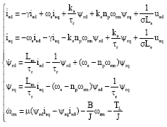
The dynamic model of an IM is described in a synchronous two-axes reference frame by Krishnan (2001):
![]() | (1) |
where, ψrd, ψrq, isd, isd, usd, usd are the rotor flux linkages, the stator currents and voltages in d-q axes, respectively. σ = 1-L2m/(Ls Lr), ks = Lm/(σ Ls Lr), τr = Lr/Rr, τs = Ls/Rs, γ = 1/στs+1-σ/στr, μ = npLm/(JLr), Lm, Lr, Ls, Rr, Rs are the mutual inductance, rotor inductance, stator inductance, rotor resistance and stator resistance, respectively. ωm is the rotor speed, B is the viscous friction coefficient, J is the rotor moment of inertia, np is the number of pairs of rotor poles and TL is the load torque. The synchronous speed can be calculated as ωs = npωrm+Lmisq/(τr ψrd). The voltages usd and usq are the control inputs of the system (Eq. 1). The stator currents and rotor speed are measurable quantities which are obtained by Hall-effect current transducers and encoder.
DESIGN OF ROBUST FUZZY VARIABLE STRUCTURE CONTROLLER
Output tracking based on T-S fuzzy control: To investigate the control design of system (Eq. 1), we let the state vector x (t) = [isd, isq?, ψrd, ψrd, ωm]T, the control input vector u (t) = [usd, usq]T and the measured output y (t) = [isd, isq, ωm]T. Then, the state equations of IM considered here can be represented as:
![]() | (2) |
Where:
![]() |
A11 = -γI+ωJs, A12 = Ks/τrI+Ks np ωmJ, A21 = M/τrI, A22 = -1/τrI+(ωs-np ωm) J, A32 = μ [isd isd], A33 = -B/J, B = 1/σLs [I, 0]T:
![]() |
D = [0 0 -1/J]T:
![]() |
The load torque is regarded as the external disturbance, i.e. w (t) = TL.
The nonlinear system (Eq. 2) can be expressed by the T-S fuzzy model:
Plant rule i: If z1 (t) is F1, i, z2 (t) is F2, i,
and zg (t) is Fg, i (t), Then, , i = 1, 2, ..., r.
By using the fuzzy inference method with a singleton fuzzifier, product inference and center average defuzzifier, the fuzzy model (Eq. 2) can be expressed as the following global model:
![]() | (3) |
where, Ais are the system matrices with appropriate dimensions, z (t) = [z1, z2, ..., zg]T is the premise variable vector that consists of the system states, r is the number of fuzzy rules and:
![]() |
for all t. The terms Fji (zj (t)) are the fuzzy set. It is assumed, as usual, that wi≥0 and hi≥0 and:
![]() |
for all t and i = 1, 2, ..., r.
However, it is noted that system (Eq. 3) is only a linearized fuzzy model of IM without considering any model uncertainty or external disturbance. Therefore, we take the above perturbations into account and modify the uncertain T-S fuzzy systems (Eq. 3) as:
![]() | (4) |
where,
![]() |
denotes the whole uncertainties including parameter variations and load disturbances.
From Eq. 4, it is easy to find that the uncertainties dont satisfy the so-called matching conditions. Thus, the H∞ robust technique should be adopted to alleviate the adverse impact on the control performance.
For speed tracking control of IM, the control objective is required to satisfy (ωm (t)-(ωmd (t))→0 as t→4 and the amplitude of the rotor flux linkage:
![]() |
keeps constant, where ωmd is the desired speed signal. In order to convert the output tracking problem into a stabilization problem, we introduce a set of internal desired states, xr = [isdr, isqr, ψrdr, ψrqr, ωmr]T which are to be tracked by the state vector x (t).
Let denote the tracking error for the state variables. The time derivative of
yields:
![]() | (5) |
In Eq. 5, the new control input is calculated as follows:
![]() | (6) |
According to the above description, we can find that the tracking control is converted to the stabilization problem. Then, our control purpose is to design the new controller τ (t) to make the new state .
The PDC offers a procedure to design a fuzzy controller from a given T-S fuzzy model. In the PDC design, each control rule is designed from the corresponding rule of a T-S fuzzy model (Tanaka and Wang, 2001). The designed fuzzy controller shares the same fuzzy sets with the fuzzy model in the premise parts as follows
Control rule i: If z1 (t) is F1, i, z2 (t) is F1, I,
and zg (t) is Fg, i, Then , i = 1, 2, ..., r.
The PDC can be represented by:
![]() | (7) |
where, the feedback gains Ki = MiX-1 will be determined by solving the following LMIs such that the overall stability is guaranteed:
![]() | (8) |
![]() | (9) |
where, X is a positive-definite matrix.
H∞ fuzzy variable structure control: Design of our HFVSC controller involves two important phases. The first phase is to design a suitable sliding surface function S so that once the system enters the hyper-plane S, the desired dynamic characteristics can be realized. The second is to design a proper controller τ (t) instead of Eq. 7 so that it can drive the systems dynamics into the designed hyper-plane and stay thereafter.
We first define the linear sliding surfaces as follows. The proposed sliding mode function is:
![]() | (10) |
where, CεRnxm is the designed SMC coefficient and C should be properly choiced so that the equivalent control of SMC would be really existed (Choi, 2009).
For the design of the variable structure, it is necessary to have the prior knowledge of the upper bounds of uncertainties and disturbances. The variation of load torque would impose adverse effect on the control performance. Generally, for a given IM system, the maximum of the allowable torque is known and certain; therefore, the bound is easy to obtain. There exists known positive constant ψw such that the following inequality is fulfilled:
![]() | (11) |
where, the notation ||.|| denotes the Euclidian norm of the vector and ψw is the upper bound of the uncertainties.
Then, the proposed HFVSC controller in this study is designed as:
![]() | (12) |
where,
![]() | (13) |
![]() | (14) |
where, r0, r1 are designed parameters and sign (.) is the sign function.
The following theorem proves that the stability of the proposed controlled system is guaranteed if the sliding surface (Eq. 10) and controller (Eq. 12) are employed.
Theorem 1: If there exist matrices Q>0 and Y such that the following LMI holds:
![]() | (15) |
where, K = YP and P = Q-1, the state trajectories of the close-loop system Eq. 5 under the control law (Eq. 12-14) will reach the sliding surface defined in Eq. 10 within finite time and the motion of system (Eq. 5) confined on the sliding surface has the robus H∞ performance.
Proof: We firstly analyse the reachability of the above controller. The time derivative of the sliding mode function is obtained as:
![]() | (16) |
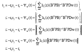
Let sj denote the jth element of the sliding mode S, then it is evident that |sj|≤ ||S||. Once the inequality sj>0 holds, Eq. 16 can be rewritten as:
![]() | (17) |
In the same way, if sj>0 holds, Eq. 16 can be rewritten as:
![]() | (18) |
From Eq. 17 and 18, if S (t)≠0, the inequality holds; thus, the sliding function S (t) will reach to zero with finite time and the system states reach the sliding surface.
Once the required sliding surface is obtained, the next step it to design the control law that drives the trajectories to the sliding surface and maintains it on the sliding surface. To achieve this goal, a proper control matrix P in Eq. 15 should be choosen.
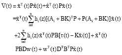
Now consider a Lyapunov function given as follows:
![]() | (19) |
The time derivative of the Lyapunov function V can be obtained as follows:
![]() | (20) |
To ensure the asymptotical stability of the control system, the time derivative of V should satisfy the inequality ; On the other hand, to achieve the robust H∞ performance on the state error, the following inequality should be satisfied:
![]() | (21) |
Once the system states reach the sliding surface, S (t) = 0 and ; thus, the second term in the right hand of Eq. 20 equals zero. If there exist a matrix P such that the following inequality holds:
![]() | (22) |
Then, we have Wh (t)<0. Now, the state trajectories of the system (Eq. 5) will be restricted on the sliding surface and its motion has the robust H∞ performance. The inequality Eq. 22 can be transformed into the following LMI:
![]() | (23) |
The inequality Eq. 23 is equivalent to the following:
![]() | (24) |
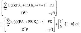
According to the Schur complemental lema, we have:
![]() | (25) |
If the LMI (Eq. 25) holds, the inequality Eq. 21 and 22 also hold; thus, the derivative is satisfied. Thus, the control law (Eq. 12) drives the state error trajectories of the system in (Eq. 5) onto the sliding surface (Eq. 10) and the system is stable. After the new controller τH_FVSC (t) is designed, the original control input u(t) can be derived by using Eq. 6.
SIMULATION RESULTS
Application of the proposed HFVSC controller on IM: To show the effectiveness of the proposed methods, the IM drive with motor parametric uncertainties and load disturbances is formulated. The system in Eq. 2 can be exactly represented by the following T-S fuzzy model:
Plant ruleRi: If z1 (t) is M1, j(i), z2 (t) is M2, j(i) and z3 (t) is M3, j(i), Then where, Ri denotes the ith rule and j (i) = 1, 2, i = 1, 2, ..., 8. M1,1, M1,2, M2,1, M2,2, M3,1, M3,2 are fuzzy sets. Ai and Bi represent the system matrix and the control matrix of the ith sub-system. We have B1 = B2 = ... = B8 = B and Ai can be easily determined according the T-S modelling theory as following:
![]() |
where, ai = ai1 ai2 ai3, i = 1, 2, , 8, are defined as a1 = (D3D2D1), a2 = (d3D2D1), a3 = (D3d2D1), a4 = (d3d2D1), a5 = (D3D2d1), a6 = (d3D2d1), a7 = (D3d2d1), a8 = (d3d2d1).
We can choose zg, g = 1, 2, 3, as the premise variables and define z1 (t) = isd (t), z2 (t) = isq (t), z3 (t) = ωm(t). The universe of the premise variable is Ug = [dg, Dg] where, dg = min (zg) and Dg = max (zg). Thus, Ug can be divided into two fuzzy subspaces and eight linear sub-system is obtained to represent the induction motor. When designing the global controller, the local controllers are integrated together through the membership function hi. The corresponding membership functions are:
![]() |
where, Mi(i) is the membership function of the fuzzy set Mi,j(i) and:
![]() |
Simulation results: The proposed HFVSC scheme has been tested in simulation. The 3-phase 4 Kw induction motor is characterized by the following parameters:
• | Rated line voltage = 380V |
• | Rated speed = 1440 r min-1 |
• | Stator resistance Rs = 1.2 Ω |
• | Rotor resistance Rr = 1.8 Ω |
• | Stator inductance Ls = 155.4 mH |
• | Rotor inductance Lr = 156.8 mH |
• | Mutual inductance Lm =150 mH |
• | Moment of inertia J = 0.07 kg m2 |
• | Pair of poles P = 2 |
The universes of premise variables are defined as: [d1, D1] = [-100A,100A], [d2, D2] = [-10A,10A], [d3, D3] = [0, ωM] where, the maximal speed ωM=150 rad sec-1.
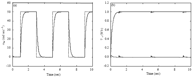
In order to show the high performance tracking of the proposed scheme, at the first case, the 50 rad sec-1 square-wave speed command and 1 Wb rotor flux command are firstly considered. The speed tracking and the actual flux amplitude are shown in Fig. 1a and b, respectively. It can be seen that the actual speed can well track the command signal and the speed response is fast. The d-axis flux rises to 1 Wb within 1 sec and the q-axis flux has a small fluctuation and nearly equals to zero.
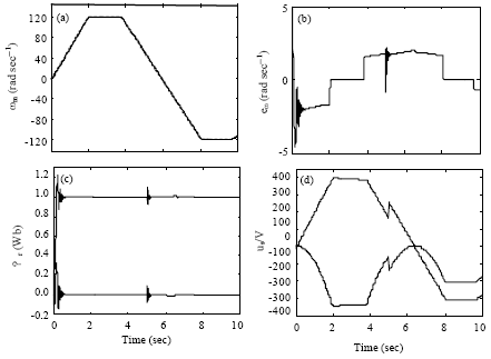
At the second case, consider the trapezidal speed tracking for the desired speed reference with parametric uncertainties. To verify the robustness to the change of system parameters, the rotor resistance and the friction coefficient are increased to 200% of their rated values (Rr = 2Rrn, B = 2Bn), respectively. In this case, the motor starts from a standstill state and we want the rotor speed to follow a triangular speed command that starts from zero and accelerates until the rotor speed is 120 rad sec-1 with 2 sec. Then, at time t = 4 sec, the reference speed decelerates and at time t = 8 sec, the reference speed reverses to -120 rad sec-1. The system starts under no load and at t = 5 sec the load torque steps from TL = 0 N.m to TL = 50 N.m while at t = 8 sec the load torque is removed. Therefore, this case involves changes both in the reference speed and in the load torque. The flux command is still equal to 1 Wb.
Figure 2a shows the desired rotor speed (dashed line) and the real rotor speed (solid line). As it may be observed, the rotor speed tracks the desired speed in spite of system uncertainties. The maximal tracking error is less than 3 rad sec-1 as in Fig. 2b. Moreover, the speed tracking is not affected by the load torque change at the time t = 5 sec, because when the sliding surface is reached (sliding mode), the system becomes insensitive to the boundary external disturbances. As shown in Fig. 2c, the amplitudes of d-q axis rotor flux basically remain unchanged despite of a small fluctuation in startup and the moment of sudden load change. Figure 2d gives the control inputs when using our control laws (Eq. 12,13 and 14). The original control input u (t) is bounded and varies with the speed command. As it can be seen, the chattering phenomenon of control input is effectively alleviated.
![]() | |
Fig. 1: | Response under square wave command, (a) speed tracking and (b) rotor flux amplitude |
![]() | |
Fig. 2: | Response for triangular wave command, (a) speed tracking curve, (b) speed tracking error, (c) rotor flux amplitude and (d) stator voltages |
![]() | |
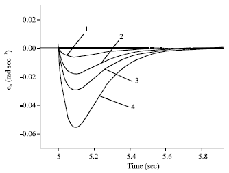
Fig. 3: | Speed tracking error under different load torque: 1-TL = 20 N.m; 2-TL = 50 N.m; 3-TL= 80 N.m; 4-TL = 120 N.m |
At the third case, the motor starts and accelerates until the steady state at 100 rad sec-1. At the time t = 5 sec, a load torque is applied to the motor. Figure 3 gives the speed tracking error curves under different load torque. As it may be observed, the rotor speed tracking error is less than 0.06 rad sec-1. Moreover, the speed tracking is not affected by different load torque by reason of the inherent property of sliding-mode motion. Therefore, compared with other existing fuzzy methods present scheme has a faster speed response and high control performance.
CONCLUSION
In this study, by combining the powerful approximation of the T-S fuzzy model and the easy implementation of the variable structure controller, an H∞ fuzzy VSC controller is proposed to achieve the accurate, fast and robust speed tracking for the induction motor. Simulations results have been carried out to verify the feasibility and the validity of the proposed control scheme. Compared with existed control scheme, the H_FVSC has the following merits and novelties.
Unlike the traditional model-based controller, the proposed approach does not need the exact mathematical model of IM and the global dynamics are simulated by the T-S model with proper fuzzy rules and fuzzy memeberships.
Unlike the traditional VSC method, H∞ technique is introduce to resist the parameter uncertainties and the load torque disturbance, thus, the additional enhanced robustness can be obtained besides that of VSC.
Also, the structure of the proposed controller composes the T-S fuzzy control part and the sliding mode supervision part, thus, both merits of them can be achieved.
ACKNOWLEDGMENT
The authors are grateful to the reviewers work and the National Natural Science Foundation of China-Key Program for the support of this work through the research under Grant NSFC- 60835004.
REFERENCES
- Asseu, O., M. Koffi, Z. Yeo, X. Lin-Shi, M.A. Kouacou and T.J. Zoueu, 2008. Robust feedback linearization and observation approach for control of an induction motor. Asian J. Applied Sci., 1: 59-69.
CrossRefDirect Link - Asseu, O., Z. Yeo, M. Koffi, M.A. Kouacou and K.E. Ali, 2010. Sensorless control of induction machines using a reduced order extended kalman filter for rotor time constant and flux estimation. J. Applied Sci., 10: 399-405.
CrossRefDirect Link - Asseu, O., Z. Yeo, M. Koffi, T.R. Ori, G.L. Loum, T.J. Zoueu and A. Tanoh, 2009. Reduced-order sliding mode flux observer and nonlinear control of an induction motor. Trends Applied Sci. Res., 4: 14-24.
CrossRefDirect Link - Bortolet, P. and R. Palm, 1997. Identification, modeling and control by means of takagi-sugeno fuzzy systems fuzzy systems. Proceedings of the 6th IEEE International Conference, July 1-5, Barcelona, Spain, pp: 515-520.
CrossRef - Cao, Y.Y. and P.M. Frank, 2000. Robust H∞ disturbance attenuation for a class of uncertain discrete-time fuzzy systems. IEEE Trans. Fuzzy Syst., 8: 406-415.
CrossRef - Chang, Y.H. and Y.Y. Wang, M.H. Hung and P.C. Chen, 2005. Regional stability and H∞ performance control of an input-saturated induction motor via LMI approach. Asian J. Control, 7: 368-379.
CrossRefDirect Link - Choi, H.H., 2008. Output feedback variable structure control design with an H2 performance bound constraint. Automatica, 44: 2403-2408.
CrossRef - Choi, H.H., 2009. Output feedback stabilization of uncertain fuzzy systems using variable structure system approach. Fuzzy Sets Syst., 160: 2812-2823.
CrossRef - Feng, G., 2006. A survey on analysis and design of model-based fuzzy control systems. IEEE Trans. Fuzzy Syst., 14: 676-697.
CrossRef - Hong-Qiang, W., W. Dao-Bo, A.A. Mian and D. Hai-Bin, 2008. Multi-mode flight control for an unmanned helicopter based on robust H∞ D-stabilization and PI tracking configuration. Space Res. J., 1: 39-52.
CrossRefDirect Link - Jamoussi, K., M. Chadli, A. El Hajjaji and M. Ouali, 2010. Robust fuzzy sliding mode observer for an induction motor. J. Electron. Eng. Theor. Appl., 1: 42-51.
Direct Link - Lasaad, S., Z. Dalila and A.M. Naceurq, 2007. Adaptative variable structure control for an online tuning direct vector controlled induction motor drives. J. Applied Sci., 7: 3177-3186.
CrossRefDirect Link - Prempain, E. and I. Postlethwaite, 2002. H-infinity design for an induction motor. Proceedings of the International Federation of Automatic Control World Congress, (IFACWC`02), Barcelona, Spain, pp: 30-30.
CrossRef - Zhang, X.Z. and Y.N. Wang, 2009. Fuzzy variable structure control based on a Takagi-Sugeno model for permanent-magnet synchronous motors. J. Syst. Control Eng., 223: 773-783.
CrossRef - Ali, H.K., 2011. Fuzzy controller design of servo system. Asian J. Applied Sci., 4: 403-413.
CrossRef