
H. Nahvi
Department of Mechanical Engineering, Isfahan University of Technology, Isfahan, Iran
H. Ahmadi
Department of Mechanical Engineering, Isfahan University of Technology, Isfahan, Iran
Journal of Applied Sciences
Year: 2003 | Volume: 3 | Issue: 7 | Page No.: 510-523


ABSTRACT
Mechanical flexibility of robotic manipulators is a major problem in motion control. The slender, flexible mechanical structure may cause undesirable vibrations, which has to be controlled in order to achieve satisfactory performance. To control flexible systems, an accurate dynamic model is essential. Basically, two types of flexibility exist in the robots; link flexibility and joint flexibility. Both have been addressed in the literature, individually or together. In this paper, a dynamic model for a two arm flexible manipulator, carrying a payload with rotary inertia, is presented. Arm and joint flexibilities are considered. The Lagrangian approach in conjunction with the finite element method is employed in deriving the equations of motion. All the dynamic coupling terms between the system reference rotational motion, joint torsional flexibility and arm bending flexibility are considered. The results of numerical simulation show the significant effect of joint flexibility in the vibrations of compliant manipulators in the form of high frequency and small amplitude vibrations. The effects of the payload are shown to be increasing the amplitude of vibrations and decreasing the frequency of oscillations. The dynamic model is highly nonlinear and the dynamical equations of motion are solved using numerical integration procedures.
PDF Abstract XML References Citation
How to cite this article
H. Nahvi and H. Ahmadi, 2003. Dynamic Simulation and Nonlinear Vibrations of Flexible Robot Arms. Journal of Applied Sciences, 3: 510-523.
DOI: 10.3923/jas.2003.510.523
URL: https://scialert.net/abstract/?doi=jas.2003.510.523
DOI: 10.3923/jas.2003.510.523
URL: https://scialert.net/abstract/?doi=jas.2003.510.523
INTRODUCTION
Using light-weight elements in space mechanisms and robotic chains has increased the tendency for modeling flexibility of elements and joints. Dynamic modeling of rotational flexible members has noticed extensive attention in two previous decades and has been a suitable tool for design and control purposes. Considering flexibility of joints in dynamic modeling of rotational members is more complicated and realistic, especially in high speeds.
Xi et al. (1994) studied the coupling effects between link and joint deflections in a manipulator, using natural frequencies of the system. By introducing inertia and stiffness ratios, coupling effects are discussed for two cases: a rigid member with a flexible joint and a flexible member with a rigid joint. Gamara and Yuhara (1999) presented dynamic model of a flexible robot manipulator with two flexible members and flexible joints. Dynamic equations obtained using Newton-Euler method and finite element method is used for dynamic analysis. Usoro et al. (1986) used Lagrange method in association with finite element method for mathematical modeling of light-weight flexible manipulators. Elemental kinetic and potential energies are used to develop dynamic model of the system. Simulation results for a two-arm manipulator under its weight with no external excitation are presented. Low (1994) presented vibration analysis of a rotating beam carrying a tip mass at its end. Using Hamilton’s principle the system equations of motion and the associated boundary conditions are derived. Li et al. (1998) presented a systematic approach to dynamic modeling and mode analysis of a single-link flexible robot, which has a flexible joint, a hub at the base end and a payload at the free end. They showed that for a given flexible system, the fundamental frequency is mainly affected by the payload mass, while the second frequency is mainly affected by the payload inertia. A new flexible rotor beam element is suggested by Shigang et al. (1997) to study the dynamic behavior of flexible manipulators. They showed that joint flexibility plays a significant role in the dynamic behavior of flexible manipulators. Recently, Al-Bedoor and Almusallam (2000) used small deformation theory to model a rotating flexible arm driven through a joint, which is flexible in torsion. They have shown that the joint torsional flexibility has a pronounced effect on the dynamic behavior of the system.
In this paper, a dynamic model for a two arm flexible manipulator, carrying a payload with rotary inertia, is presented. Arm and joint flexibilities are considered in the analysis.
Dynamic model
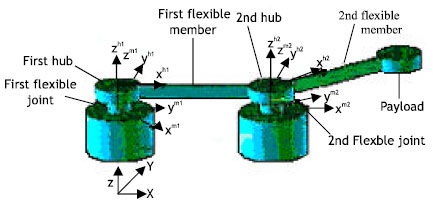
In this section a dynamic model for a two-member robot with flexible links and joints is developed. Schematic diagram of the flexible two-member robot is shown in Fig. 1. Suppose that the joints or motors axis are flexible and experience small torsional deformations. The hubs are assumed to be rigid and flexible members are joined to the hubs radially, so that the longitudinal axis of members is in the direction of hub’s radius. The members are assumed to be inextensible and the Euler-Bernoulli beam theory is adopted for the analysis.
The coordinate systems used in the model are shown in Fig. 1 and 2. XY is the inertial reference frame. xm1ym1 is the body coordinate system attached to the first arm motor shaft. In fact, this coordinate is the same local coordinate attached to the first joint. The body coordinate attached to the second motor shaft is xm2ym2 which is the same local coordinate attached to the second joint. Another body coordinate system xh1yh1 is attached to the first hub and xh1 axis is in the direction of undeformed longitudinal axis of the first arm. xh2yh2 is a body coordinate system attached to the second hub and xh2 axis is in the direction of undeformed longitudinal axis of the second arm.
The first arm has n1 elements. The ith element has two nodes, I and I+1. Each element has a local coordinate system xy attached to it’s first node I. The position of the ith element coordinate system is defined by the position of the first node, Si, in the local coordinate system xh1yh1. The second arm has n2 elements with similar characteristics as that of the first arm in its local coordinate system.
Kinetic energy of the system
The total kinetic energy contains kinetic energies of the first and second members. The end position of the first member is defined by:
| (1) |
where ![]() is the position vector of the end position of the first link in the hub coordinate system xh1yh1, given by:
is the position vector of the end position of the first link in the hub coordinate system xh1yh1, given by:
| (2) |
u2n+1(x,t) and L1n1 are transverse elastic displacement of the end position and length of the first member, respectively. The global position vector of a point p on the ith element of the second member can be written as:
| (3) |
| (4) |
| (5) |
where ![]() is the position vector of point p in the body coordinate system of the second hub, xh2yh2 and [A(θ1)] and [A(θ2)] are the rotational transformation matrices from the motor coordinate system xm1ym1 to the XY inertial system and from the motor coordinate system xm2ym2 to the reference frame with angle θ1, respectively. [A(Ψ1)] and [A(Ψ2)] are the rotational transformation matrices from the hub coordinate system xh1yh1 to the motor coordinate system xm1ym1 and from the hub coordinate system xh2yh2 to the motor coordinate system xm2ym2, respectively. u(x,t) and Si are the transverse elastic displacement of point p and the axial position of the ith node, measured relative to the xh2yh2 coordinate system, respectively. θ1 and θ2 express the rigid body rotations of members and Ψ1 and Ψ2 are small torsional deformation angles measured relative to the motor coordinate systems.
is the position vector of point p in the body coordinate system of the second hub, xh2yh2 and [A(θ1)] and [A(θ2)] are the rotational transformation matrices from the motor coordinate system xm1ym1 to the XY inertial system and from the motor coordinate system xm2ym2 to the reference frame with angle θ1, respectively. [A(Ψ1)] and [A(Ψ2)] are the rotational transformation matrices from the hub coordinate system xh1yh1 to the motor coordinate system xm1ym1 and from the hub coordinate system xh2yh2 to the motor coordinate system xm2ym2, respectively. u(x,t) and Si are the transverse elastic displacement of point p and the axial position of the ith node, measured relative to the xh2yh2 coordinate system, respectively. θ1 and θ2 express the rigid body rotations of members and Ψ1 and Ψ2 are small torsional deformation angles measured relative to the motor coordinate systems.
The velocity vector of point p may be derived by differentiating equation (3) and substituting for rotational matrices and position vectors from equations (4) and (5). The kinetic energy of the ith element on the second member with mass per unit length ρ2 and length l2 may be written as:
| (6) |
The kinetic energy expressions for hubs and joints may be expressed as:
 | (7) |
where Jh1, Jh2, Js1 and Js2 are the mass moments of inertia of the hubs and joints about their centerlines, respectively.
 | |
| Fig. 1: | Schematic diagram of the flexible two-member manipulator |
Since, these expressions are local kinetic energies, the global kinetic energies may be obtained by adding the term mR2 related to each term, to equations (7). The kinetic energy of the elements of the first member,Uil, may be computed with the same procedure.
The total kinetic energy of the system may be calculated as:
| (8) |
Potential energy of the system
The potential energy of the system consists of the elastic strain energy of the links and joints, the potential energy of the axial shortening due to transverse deformation and inertial forces and the gravitational potential energy. The potential energies stored in the members with elastic rigidity EI and in the joints with torsional stiffness kt are given, respectively, as:
 | (9) |
The gravitational potential energies of the ith element of the first and second members due to reference motion may be expressed, respectively, as:
 | (10) |
The axial shortening potential energy produced by transverse deformations is given by:
| (11) |
where is Fp2 the axial inertial force at point p due to the reference motion of element i of the second member, given by:
 | (12) |
where the first part expresses the inertia force of the ith element and the second part represents the influence of inertia forces of all the elements to the right of element i. dδ is the axial shortening due to the transverse deformations, given approximately as:
| (13) |
The elemental potential energy of the first member may be calculated with the same procedure.
The total potential energy of the system may be written as:
| (14) |
Discretizing with finite element method
The finite element method is used to discretize elastic members. In this method, deformations are expressed in terms of the nodal degrees of freedom as:
| (15) |
where [N] is matrix of the shape functions and {q} is vector of the nodal degrees of freedom.
Substituting equation (15) into equations (8) and (14), the kinetic and potential energies may be obtained. The Lagrangian of the system may be expressed in terms of θ1, θ2, Ψ1, Ψ2, q1, q2,…., q2n1+2n2+2, as:
| (16) |
The boundary conditions dictate q1 and q2 to be zero. The equations of motion may be obtained using Lagrange’s equations in the following form:
 | (17) |
where Qi represents moment or general force applied to the ith degree of freedom of the system.
Dynamics of the payload
The payload, as shown in Fig. 1, is located at the tip of the second member with a mass of mL and a moment of inertia JL about its mass center. To obtain kinetic and potential energies of the payload, position vector of the payload in the coordinate system XY may be written as:
| (18) |
where ![]() and rend1 are position vectors of the payload in the xh2yh2 coordinate system and the tip of the first arm, respectively, given as:
and rend1 are position vectors of the payload in the xh2yh2 coordinate system and the tip of the first arm, respectively, given as:
 | (19) |
where SL1 and SL2 are the axial positions and u(L1,t) and u(L2,t) are transverse elastic deformations of the ends of the two arms.
The kinetic energy of the payload may be calculated as:
| (20) |
where the first part expresses the translational kinetic energy of the payload and the second part is the rotational kinetic energy of the payload. The velocity vector of the payload may be obtained by differentiating equation (18).
The potential energy of the payload consists of two parts; the gravitational potential energy and the axial shortening potential energy. The gravitational potential energy is due to the rigid body motion and may be expressed as:
| (21) |
The axial shortening potential energy is due to the inertial forces of the payload and may be represented as:
| (22) |
Utilizing Lagrangian of the payload, equations of motion of payload may be obtained using Lagrange’s equations. Finally, the entries of equations of motion of the payload are added to the corresponding entries of the equations of motion of the whole system. The system of second-order equations of motion is transformed into a system of first-order equations. A computer scheme is developed to integrate equations of motion. Simulation results are presented in the next section.
Simulation and Results
Dimensions and material properties of the members are shown in Table 1. The torque profiles in the form of sine functions with different amplitudes, which are applied to the joints, are shown in Fig. 2 and 3. Each member is modeled with two elements.
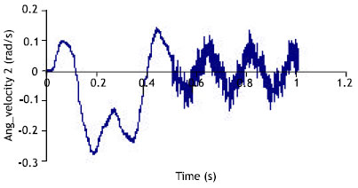
Fig. 4 and 5 show the angular positions of the first and second members that vibrate around its initial releasing condition. Change of angular velocities of the two members are shown in Fig. 6 and 7. The oscillating behavior of the first member is a small amplitude and high frequency vibration superposed on the motion of the link with the frequency of the applied torque. The pronounced effect of the joint torsional flexibility on the tip deflection of the arms can be seen in Fig. 8 and 9. Second mode of vibration of the links is strongly excited on the bending deformations of the members. Joint torsional deflection and the torsional velocity of the first member are shown in Fig. 10 and 11. The high amplitude oscillations in Fig. 11 are due to the nonlinear interaction between the joint torsional deflections and the arm bending deformations.
It should be mentioned that the angular positions of the arms significantly change by varying amplitudes of the applied torques. If the applied torques have the same amplitude, the angular position of the first arm will be clockwise. If amplitude of the applied torque to the first joint is twice the amplitude of the torque applied to the second joint, the torque applied to the first arm balances the reaction of the second arm, causing the angular position of both links to be in the same direction, counterclockwise. Also, the response of the second arm is similar to the response of a single link manipulator and the second member acts as a payload on the first member.
To show the effects of the payload on the vibration behavior of the system, the amplitude of applied torques are increased to compensate the added payload inertia. Fig. 12-15 show angular positions and angular velocities of the two members, respectively. It may be seen that adding payload at the tip of the second member significantly changes vibration behavior of the system, especially that of the second link. The payload increases the amplitude of oscillations and decreases the frequency, due to added inertia. The senses of angular position and angular velocity of the second link reverses and another mode of vibration is observed in the response of the system. Tip deflections of the members are shown in Fig. 16 and 17.
 | |
| Fig. 2: | Deformed configuration of the flexible two member manipulator |
 | |
| Fig. 3: | Applied torque to the first member |
 | |
| Fig. 4: | Applied torque to the second member |
 | |
| Fig. 5: | Angular position of the first member |
 | |
| Fig. 6: | Angular position of the second member |
 | |
| Fig. 7: | Angular velocity of the first member |
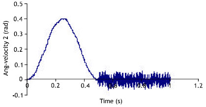 | |
| Fig. 8: | Angular velocity of the second member |
 | |
| Fig. 9: | Tip deflection of the first member |
 | |
| Fig. 10: | Top deflection of the second member |
 | |
| Fig. 11: | Torsional deflection of the first member |
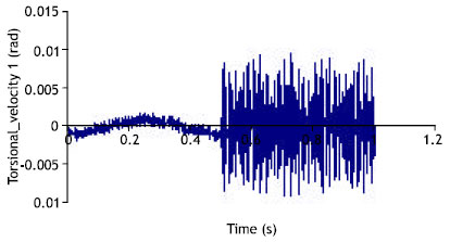 | |
| Fig. 12: | Torsional velocity of the first member |
 | |
| Fig. 13: | Angular position of the first member with payload |
 | |
| Fig. 14: | Angular position of the second member with payload |
 | |
| Fig. 15: | Angular velocity of the first member with payload |
 | |
| Fig. 16: | Angular velocity of the second member with payload |
 | |
| Fig. 17: | Tip deflection of the first member with payload |
 | |
| Fig. 18: | Tip deflection of the second member with payload |
| Table 1: | Dimensions and material properties of the manipulator |
 | |
It may be seen that the amplitudes of vibrations are increased as a result of increase in the applied torque magnitudes and the frequency of the oscillations are decreased when the payload is added to the system.
A dynamic model for a two-member flexible robot with a payload has been developed. The joint compliance and link flexibility have been considered. The results from the numerical simulation showed the significant effect of joint flexibilities in the dynamics and vibration behavior of flexible manipulators, therefore, in the design and control of compliant manipulators should be considered in addition to the link flexibility.
REFERENCES
- Al-Bedoor, B. and A. Almusallam, 2000. Dynamics of flexible-link and flexible-joint manipulators carrying a payload with rotary inertia. Mechanism Machine Theory, 35: 785-820.
Direct Link - Gamarra-ado, V. and E. Yuhara, 1999. Dynamic modeling and simulation of flexible robotic manipulators. Robotica, 17: 523-528.
CrossRefDirect Link - Li, D., D.J. Zu and A.A. Goldberg, 1998. Dynamic modeling and mode analysis of flexible-link, flexible-joint robots. Mechanism Machine Theory, 33: 1031-1044.
Direct Link - Shigang, Y., Y. Yueqing and B. Shixiam, 1997. Flexible rotor beam element for the manipulators with joint and link flexibility. Mechanism Machine Theory, 32: 209-219.
Direct Link - Usoro, P., R. Nadira and S. Mahil, 1986. Finite element lagrange approach to modeling light-weight flexible manipulators. J. Dyn. Syst. Measur. Control, 108: 198-203.
CrossRefDirect Link - Xi, F., R.G. Fenton and B. Tabbarok, 1994. Coupling effects in a manipulator with both flexible link and joint. J. Dyn. Syst. Measur. Control, 116: 826-831.
Direct Link