

Hui Xie
Key Laboratory of Signal and Information Processing, Chongqing Three Gorges University, Chongqing, 404100, China
Hongbing Li
Key Laboratory of Signal and Information Processing, Chongqing Three Gorges University, Chongqing, 404100, China
Heping Liu
State Key Laboratory of Power Transmission Equipment and System Security and New Technology, Chongqing University, Chongqing, 400030, China
Qiang Chen
Key Laboratory of Signal and Information Processing, Chongqing Three Gorges University, Chongqing, 404100, China
Information Technology Journal
Year: 2013 | Volume: 12 | Issue: 12 | Page No.: 2366-2373


ABSTRACT
The output voltage of the Sinusoidal Pulse Width Modulation (SPWM) inverter contains various ultra harmonics. It increases the system’s power consumption and generates the harmonic interference. By establishing the mathematical model of the three-phase inverter and doing the FFT transformation on the output voltage, it analyses the relation between the output voltage and the combined conduction states of the inverter’s switches during one waveform cycle, it also analyzes the main parameters, modulation ratio of the voltage and carrier signal which can affect the inverter’s harmonic content. Simulation verifies the distribution regularities of each harmonic of SPWM inverter’s output voltage. It indicates that SPWM modulation method can make the output harmonics high frequency, the harmonic characteristic and modulation depth are closely related to the carrier frequency. This study has great significance on the rational selection of modulation depth and carrier frequency, improvement of the inverter’s efficiency and reduction of harmonic distortion.
PDF Abstract XML References Citation
Article History
Received: April 03, 2013;
Accepted: May 28, 2013;
Published: August 02, 2013
How to cite this article
Hui Xie, Hongbing Li, Heping Liu and Qiang Chen, 2013. Harmonic Wave Analysis and Suppression Research on Three-phase SPWM Inverter. Information Technology Journal, 12: 2366-2373.
DOI: 10.3923/itj.2013.2366.2373
URL: https://scialert.net/abstract/?doi=itj.2013.2366.2373
DOI: 10.3923/itj.2013.2366.2373
URL: https://scialert.net/abstract/?doi=itj.2013.2366.2373
INTRODUCTION
Three-phase inverter can suppress the harmonic wave and AC noise of the output voltage when adopting SPWM modulation mode. It has outstanding advantages in the industrial systems such as frequency control of motor speed, direct-current transmission and uninterrupted power supply (Zhang et al., 2003; Mohan et al., 2008). However, some high order harmonic components are generated by this modulation mode. It causes motor’s fever, torque ripple and even the system oscillation (Trzynadlowski et al., 2004; Deng et al., 2005; Escobar et al., 2007). Some literatures are aimed to analyze the harmonic wave of SPWM inverter. They are the qualitative studies on the topology structure of the inverter (Sun et al., 2004; Cherchali et al., 2011; Dai et al., 2012) and the improvement of reducing the Total Harmonic Distortion (THD) factor for the harmonic indicator (Shi and Li, 2005; Hu and Tan, 2009). Owning to the nonlinear characteristic of the inverter system, harmonic wave reduction is still an issue needed further study.
Based on the relevant studies of this issue, we make a further study on the waveform of output voltage generated by three-phase SPWM inverter. Then accurate analysis is made on the switching state in each switch section during one cycle. Through the Fourier transform, we obtain the harmonic distribution law. By analyzing the carrier frequency and modulation ratio, a general method of harmonic elimination is presented and it provides reference to the design of the inverter.
CIRCUIT ANALYSIS OF THREE-PHASE SPWM INVERTER
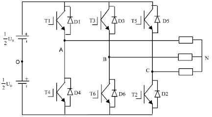
SPWM control of three-phase inverter: The main circuit of three-phase bridge inverter is as shown in Fig. 1. If the midpoint O of the DC power supply is selected as the reference, this circuit can be regarded as the three-phase inverter combined by three single-phase half -bridge inverters (Sun et al., 2012).
Each phase driven signal adopts SPWM control mode, the sine wave is selected as the modulation wave. The carrier is the bipolar triangular wave and the carrier signal is shared by three-phase modulation waves.
 | |
| Fig. 1: | Main circuit of three-phase inverter |
 | |
| Fig. 2(a-d): | Waves of three-phase inverter |
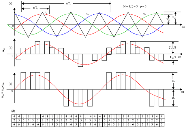
During each cycle of the output voltage, every switch is to be the state on and off many times. One bridge arm of three-phase voltage inverter has only one switch to be driven conduction any time, The drive signal of upper and lower switches is to be complemented. Therefore, three-phase voltage-inverter has three switches to be driven conduction any time. Waveform of three-phase SPWM inverter can be gotten according to the switches’ conduction and shown in Fig. 2. The carrier ratio is:
 |
where, fC is the frequency of the triangular carrier, fr is the frequency of sinusoidal modulation wave.
Figure 2a shows the triangular carrier wave uC and three-phase modulation wave uar, ubr and ucr, Fig. 2b shows the inverter’s phase voltage uAN Fig. 2c shows the inverter’s line voltage uAB, Fig. 2d shows three switch’ names for three-phase inverter in the same time.
Now we give the mathematical analysis on the phase voltage uAN and the line voltage uAB of three-phase inverter.
In Fig. 1, it uses the model of load star connection of three-phase inverter to deduce, similar as the deductive method of the triangular load which only requires a load transformation. From the conducting states of three switches at the same time in Fig. 2d, when the switches T1, T5, T6 are at the state ‘on’, the point A and C of three-phase inverter connect the positive pole, point B connects the negative pole, set the point o as the reference, the equivalent circuit can be shown in Fig. 3.
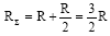
From Fig. 3 it can get the equivalent resistance:
 |
The circuit current is:
 |
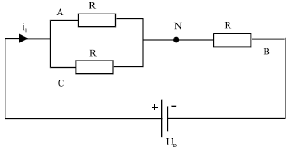 | |
| Fig. 3: | Equivalent circuit of three-phase inverter when the switches T1,T5,T6 are in the state ‘on’ |
The phase voltages of A and B are:
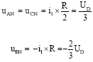 |
The line voltages of A and B are uAB = uAN-uBN = uD.
From Fig. 2d, the ratio of carrier wave:
 |
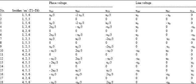
there are 18 combinations of conducting states on the condition of 6 switches in one cycle of sine wave. The analysis methods of other conducting states are same when T1, T5 and T6 are in the state ‘on’. Table 1 shows the state combination of switches during one cycle and comparison of phase and line voltages.
From Table 1, the phase voltage and line voltage of three-phase inverter’s output are composed with a series of step pulse waves. So the phase voltage uAN of three-phase inverter can be drawn in Fig. 2b and the line voltage uAB is as shown in Fig. 2c. The wave uBN and uCN are same with uAN but the phases delay, respectively 121 and 240°. So do the wave uBC and uCA, respectively 120 and 240° phases delay to the uAB.
From Fig. 2, each switch turns on and off many times during each cycle of the output voltage.
| Table 1: | The state combination of switches and comparison of the phase and line voltages |
 | |
The output of the inverter is the pulse voltage according to the sine law. It can control the amplitude and frequency of the output voltage by controlling the frequency of carrier and modulation wave.
The waveform characteristics of three-phase SPWM inverter: For the output voltage of three-phase SPWM inverter being a series of pulse voltage, it contains other frequency harmonic besides the fundamental component. According to the characteristics of the Fourier series, the amplitude of the fundamental component of the output phase voltage is:
 | (1) |
In formula 1, M = urm/ucm is the modulation ratio of SPWM inverter.
The fundamental component’s amplitude of the output line voltage uAB is:
 | (2) |
The valid value of the fundamental component of the output line voltage uAB is:
 | (3) |
Suppose that A phase modulation wave is uar = M cos ωrt, B phase modulation wave is:
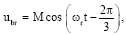 |
C phase modulation wave is:
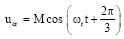 |
each bridge arm adopts double polarity based natural sampling SPWM modulation, then the analytical expression of the line voltage is:
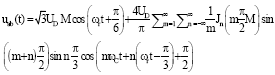 | (4) |
In formula 4, m is a non-negative integer, n is a positive integer, Jn is the first kind of Bessel function. It has the following characteristics for three-phase SPWM inverter:
| • | Frequency of the fundamental wave is same with modulation wave, the amplitude of the fundamental wave is  |
| • | From the formula: |
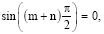 |
| it only contains the even-order sideband harmonic at the both sides of the odd harmonic with multiple frequency (including the carrier frequency) of the line voltage. Also it only contains the odd sideband harmonic at the both sides of the even-order harmonic with multiple frequency | |
| • | For sin n π/3 equal 0 when n is the multiple of 3, the line voltage does not contain the harmonic with carrier frequency and carrier doubling-frequency. It doesn’t contains the sideband harmonic with 3 times frequency at the both sides of the harmonic wave with multiple frequency (including the carrier frequency) that means the harmonic with the frequency mfc+3kfr is eliminated (m, k is positive integer) |
| • | Line voltage of three-phase SPWM only offset the harmonic wave with odd carrier frequency and cannot be completely offset the sideband harmonic cluster on both sides of the odd carrier with multiple frequency. The minimum order harmonic frequency of the line voltage is near the carrier’s frequency. When the carrier ratio N is larger, (N-2)fc is the main low-order harmonic |
SIMULATION OF THREE-PHASE SPWM INVERTER
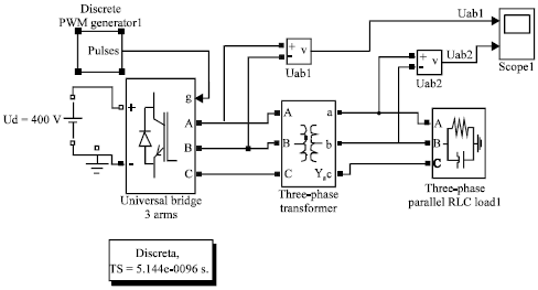
Modeling for three-phase SPWM inverter: In order to analysis and evaluate the waveform’s characteristics and harmonic distortion degree of the inverter, it establishes the simulation model in the MATLAB/Simulink. The model is as shown in Fig. 4.
In Fig. 4, the pulse drive signals of three-phase inverters are generated by the module "Discrete PWM Generator1", it drives the module of three-phase inverter "Universal Bridge three arms" to output three-phase Alternating Current (AC). The power device selects the new generation of semiconductor power switch device IGBT (Insulated Gate Bipolar Transistor).
 | |
| Fig. 4: | Simulation circuit of three-phase SPWM inverter |
The inverted line voltage by the voltage measurement module "Vab 1" is transmitted to oscilloscope to display. The harmonic signal of the inverter is filtered by the leakage inductance of three-phase transformer and the load capacitance. The filtered line voltage via the voltage measurement module is transmitted to the same oscilloscope to display and comparison.
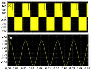
Harmonic analysis of three-phase SPWM inverter’s output voltage: IGBT is a composite power device, its operating frequency can achieve 10~40 KHZ. The switch frequency of the high-power inverter is generally controlled below 5 KHZ. To ensure the waveform symmetry of three-phase inverter, It generally selects three times as the carrier frequency (Xu and Xie, 2009) . According to the above conditions, it selects 4800 Hz as the inverter’s carrier frequency and 50 Hz as the modulation wave frequency. The modulation ratio is 0.85, as well as the inverter’s DC side voltage Ud is 400 V in Fig. 4. The line voltage uab of three-phase inverter, including the pre-filtered uab1 and filtered uab2, is simulated as shown in Fig. 5.
From Fig. 5, the line voltage, filtered by the leakage inductance of the transformer, is sine wave which is become very smooth.
Furthermore, The frequency spectrum of the line voltage uab1 and the filtered uab2 by the leakage inductance of the transformer can be obtained by FFT (Fast Fourier Transform), as shown in Fig. 6a, b. From Fig. 6a, the line voltage of the output is 293.7 V, much approximate to the theoretical value 294 V calculated by the formula 2. The sideband harmonic wave appears at the carrier frequency mfc±nfr (m, n is the positive integer), the first side harmonic wave appears at the frequency 4800±50 Hz, the second side harmonic wave appears at the frequency 9600±50 Hz and so on.
 | |
| Fig. 5(a-b): | Pre-filtered wave uab1 and the filtered wave uab2 of the line voltage of three-phase SPWM inverter (a) uab1 and (b) uab2 |
Therefore, it has less harmonic content at the other frequency and can be ignored. It should mainly consider the elimination of the first side harmonic waves when designing a filter.
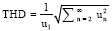
Total Harmonic Distortion Factor (THD), an important index to measure the quality of the inverter’s output voltage, is defined as:
 | (5) |
In formula 5, un is the valid value of the n-time harmonic component, u1 is the valid value of the fundamental component. Smaller the THD is, higher the quality of the waveform is (Bowes and Holliday, 2007).
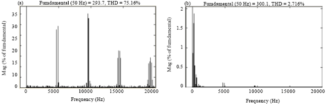 | |
| Fig. 6(a-b): | Output voltage spectrum of three-phase SPWM inverter (a) Spectrum of the line voltage uab1 and (b) Spectrum of the line voltage uab2 (M=0.85, fc=4800HZ) |
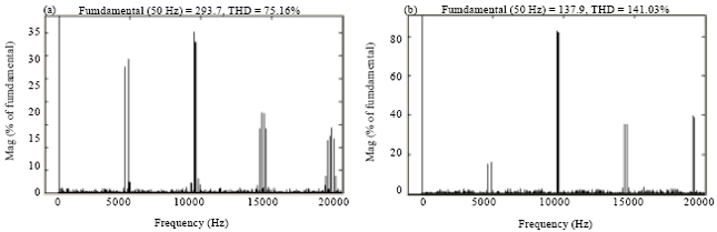 | |
| Fig. 7(a-b): | Output voltage spectrum of three-phase inverter by different modulation ratio M (a) M=0.85 (b) m=0.4 (fc=4800HZ) |
From Fig. 6a, THD of the output voltage of the SPWM inverter is not low that reaches 75.16%. In fact the design of SPWM circuit’s switch time is not reasonable, THD may be even more than 100%. However, after the SPWM modulation, harmonic frequency is modulated to high frequency direction, it no longer contains the harmonic waves which the frequency bellows the carrier harmonic waves. Even adopting small filter element, such as the transformer that it contains filter function itself, it can greatly attenuate the high frequency harmonic wave with high amplitude.
From the comparison of Fig. 6a and b, the output line voltage of the three-phase inverter is high that THD = 75.16%. However, after filtered by the leakage inductance of the transformer, its line voltage THD becomes 2.71% and contains less harmonic wave content. Also, from the time domain waveform demonstrated in Fig. 5, The filtered line voltage waveform is very smooth. By the analysis of time and frequency domain, it is shown very "clean" from the perspective of engineering application.
It makes the harmonic wave with higher frequency by the SPWM modulation so that it is easy to be filtered. This is the great advantage of the SPWM.
INFLUENCE ON HARMONIC WAVE BY INVERTER’S PARAMETER
It gives the harmonic characteristics when the carrier ratio and modulation depth of three-phase SPWM inverter are determined, it also gives the corresponding measures to restrain the harmonics. However, the carrier ratio and modulation depth are varied following system’s changes in fact.
Influence on harmonic wave by modulation ratio: Modulation ratio M of the inverter usually varies in [0, 1] to adjust the output voltage’s amplitude of the fundamental wave. Figure 7 shows the spectrum diagram of the inverter’s output voltage uab when M = 0.85 and M = 0.4. When M varies, it varies for the amplitudes of the fundamental wave of the line voltage and harmonic wave at each frequency.
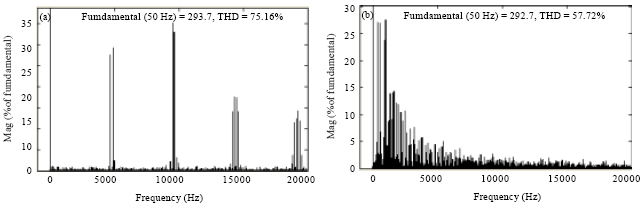 | |
| Fig. 8(a-b): | Output voltage spectrum of three-phase inverter at different carrier frequency (a) fc=4800Hz (b) fc=480Hz (M=0.85 |
This characteristic is corresponding with the analysis of the amplitude of the fundamental waves by formula 2. According to the variation of THD, the waveform distortion aggravates while the modulation ratio is decreasing. This goes against load operation. So generally the modulation ratio should be controlled more than 0.8.
In fact, the modulation ratio is not the bigger the better. When the modulation ratio M>1, it enters the over modulation. Due to the modulation amplitude exceeding the peak value of the triangular wave, it has no joint with the triangular wave during more than one carrier cycles, this can lead to the drastically reduction of the switch frequency and no longer variation of the pulse width according to the regular variation of the sine wave, So, it leads to stepping down of the frequency. Greater the over modulation is, lower the switch frequency as well as the lowest-order harmonic wave is, this will lose the advantages of SPWM. Therefore, it doesn’t make the inverter operate at the over modulation.
Influence on the harmonic wave by the carrier’s frequency: Figure 8 shows the output voltage spectrum of three-phase inverter when the modulation ratio M = 0.85, the carrier frequency is 4800 and 480 Hz.
From Fig. 8, when the carrier frequency reduces, the harmonic component dramatically increases and the distribution center of the output spectrum decreases. So it increases the designing difficulty and size of the filter, it should enhance the carrier frequency in possible. However, the carrier frequency can not be increased too much, it will cause the direct connection between the top and bottom bridge arm. If the switch frequency of the device increases, it easy appears that the pulse width is too narrow. When the pulse width is less than the device’s switch time, the device’s switch will become invalid.
CONCLUSION
| • | Ratio of the line voltage and the phase voltage of three-phase inverter has closely related with the combination of each switch’s on and off state during one cycle by SPWM modulation mode. It can change the amplitude and cycle of the output voltage by changing the switches’ conducting state |
| • | SPWM modulation makes harmonic wave higher frequency, it no longer contains harmonic wave which frequency is below the carrier wave. Three-phase SPWM inverter can also eliminate the sideband harmonic with three-time frequency which is on both sides of the double-frequency carrier (including the carrier frequency). When the carrier ratio N is larger, (N-2) fc is the main low harmonic wave |
| • | It has great influence on the harmonic distribution for SPWM modulation ratio and carrier frequency. Higher the modulation ratio is, higher the amplitude of fundamental wave is and the harmonic distortion rate will be lowered. However, the over modulation can lower the harmonic frequency and amplify the coefficients of total harmonic. Higher the carrier frequency is, less it has the harmonic content. It is limited to the power consumption of the electric power device and time constraints of switch’s dead zone. So the carrier frequency can't become too high in the consideration of the harmonic content and system performance |
ACKNOWLEDGMENT
Professor Liwan Chen and Professor Zefu Tan critically reviewed the study proposal, Dr. Xiaowei Niu and Master Zhengkun Xu collected the most data. Thanks all members of our research team.
REFERENCES
- Zhang, K., Y. Kang, J. Xiong and J. Chen, 2003. Direct repetitive control of SPWM inverter for UPS purpose. IEEE Trans. Power Electron., 18: 784-792.
CrossRef - Mohan, D.M., B. Singh and K.B. Panigrahi, 2008. A two-level 24-pulse voltage source converter with fundamental frequency switching for HVDC system. Proceedings of the IEEE International Conference on Sustainable Energy Technologies, November 24-27, 2008, Singapore, pp: 372-377.
CrossRef - Trzynadlowski, A.M., K. Borisov, Y. Li, L. Qin and Z. Wang, 2004. Mitigation of electromagnetic interference and acoustic noise in vehicular drives by random pulse width modulation. IEEE Trans. Power Electron., 1: 67-71.
CrossRefDirect Link - Deng, H., R. Oruganti and D. Srinivasan, 2005. PWM methods to handle time delay in digital control of a UPS inverter. IEEE Power Electron. Lett., 3: 1-6.
CrossRefDirect Link - Escobar, G., A.A. Valdez, J. Leyva-Ramos and P. Mattavelli, 2007. Repetitive based controller for a UPS inverter to compensate unbalance and harmonic distortion. IEEE Trans. Ind. Electron., 54: 504-510.
CrossRefDirect Link - Sun, C., Z. Bi and G. Wei, 2004. Modeling and simulation of a three-phase four-leg inverter based on a novel decoupled control technique. Proc. CSEE Chin., 24: 124-130.
Direct Link - Cherchali, N.O., A. Tlemcani, M.S. Boucherit and L. Barazane, 2011. Comparative study between different modulation strategies for five levels NPC topology inverter. Energy Power Eng., 3: 276-284.
CrossRefDirect Link - Shi, K.L. and L. Hui, 2005. Optimized PWM strategy based on genetic algorithms. IEEE Trans. Ind. Electron., 52: 1458-1461.
CrossRefDirect Link - Sun, P., C. Liu, J.S. Lai, C.L. Chen and N. Kees, 2012. Three-phase dual-buck inverter with unified pulsewidth modulation. IEEE Trans. Power Electron., 27: 1159-1167.
CrossRefDirect Link - Xu, A. and S. Xie, 2009. Research on waveform modulation technique for staircase inverters. Proc. CSEE Chin., 29: 34-39.
Direct Link - Bowes, S.R. and D. Holliday, 2007. Optimal regular-sampled PWM inverter control techniques. IEEE Trans. Ind. Electron., 54: 1547-1559.
CrossRefDirect Link