

Wu-Qi Gao
School of Computer Science and Engineering, Xi`an Technological University, Xi`an 710032, People`s Republic of China
Feng-Ju Kang
College of Marine Engineering, Northwestern Polytechnical University, Xi`an 710032, China
Bo Bai
College of Marine Engineering, Northwestern Polytechnical University, Xi`an 710032, China
Lian-Jiong Zhong
School of Computer Science and Engineering, Xi`an Technological University, Xi`an 710032, People`s Republic of China
Information Technology Journal
Year: 2012 | Volume: 11 | Issue: 7 | Page No.: 916-920


ABSTRACT
The application of a current senor in a feedback circuit is introduced in this paper and this sensor is CB0.1-CNS6B1. In order to make the variation of the load current smaller than 1% when the load resistance varies from 33.6 to 36.4 Ω, the current sensor is incorporated in the circuit. But due to the sensor’s adding, the 1 Hz’s oscillation emerged in this circuit. Based on the identification of the sensor’s model, the key factor of this problem was found through the simulation analysis. Finally, the oscillation problem in this circuit was solved with the feedback control method, thus achieving the required specification.
PDF Abstract XML References Citation
Article History
Received: November 04, 2011;
Accepted: March 29, 2012;
Published: May 29, 2012
How to cite this article
Wu-Qi Gao, Feng-Ju Kang, Bo Bai and Lian-Jiong Zhong, 2012. Analysis of a Feedback Circuit Based on the LEM Current Sensor. Information Technology Journal, 11: 916-920.
DOI: 10.3923/itj.2012.916.920
URL: https://scialert.net/abstract/?doi=itj.2012.916.920
DOI: 10.3923/itj.2012.916.920
URL: https://scialert.net/abstract/?doi=itj.2012.916.920
INTRODUCTION
According to the statistical estimate, 60% electrical equipment faults result from power (Kurt, 1999). So the feedback circuit with better fault tolerant properties become more and more important. As the equipment which can detect faults, current sensors are studied by many people (John, 1999; Aslan, 2005; Kilic, 2011; Ameri et al., 2009; Attar and Afshar, 2010; Rahaie and Kazemi, 2010; Xu and Guoyu, 2011; Chay et al., 2009; Lee and Chen, 2008; Ruan and Sun, 2011; Noaman et al., 2008; Jayakumar et al., 2006; Mezghani et al., 2006). CB0.1-CNS6B1 shown in Fig. 1 is a current sensor which is produced by LEM Company. CAO Jian introduced an application of LEM Current Sensor (Cao and Ding, 2001).
When using it, the user can put the wire which carries the current through the whole that is located in the middle of the sensor.
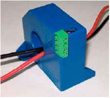 | |
| Fig. 1: | CB0.1-CNS6B1’s appearance |
And then the sensor can measure the current which flows through the wire. Specifically, the range of current which this sensor can measure is ±100 mA and the corresponding output voltage is ±5 V. The working principle of this current sensor has been introduced in many papers (Guo and He, 2003; Guan, 2004; Peng et al., 2004). The main purpose of this paper was not to study the principle of this sensor, but to discuss some problems which arise when it is used and to present their solutions.
THE EXISTING PROBLEM
The current which flows through a resistance load of about 35 Ω was tested and the voltage which is measured by the sensor back to input was fed in order to stabilize the load’s current. The results show, when the input voltage is constant, if the load resistance varies from 33.6 to 36.4 Ω, the load current’s variation cannot be bigger than ±1%. And simultaneously, when the input voltage varies between ±10 V, the load’s current can vary from 70 to -70 mA, correspondingly. Actually, it does not matter whether the current which is controlled by ±10 V is ±70 mA or not, as long as the current which is controlled by ±10 V varied linearly. Because, now that the ratio between the input and the output is constant, we can calculate the input voltage which is mapped to the ±70 mA, therefore we can give a voltage that make the circuit produce the ±70 mA current. The key task is to make the ratio change which stirred by the load variation small as much as possible. Hence, according to the theory, which the current feedback can stabilize the current, the author designed a circuit shown in Fig. 2.
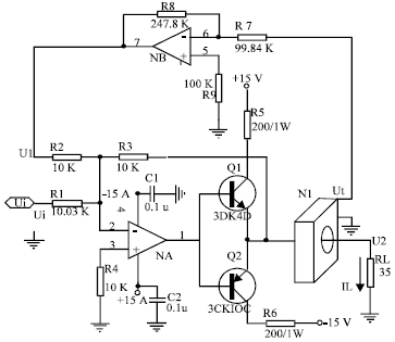 | |
| Fig. 2: | The feedback circuit which is made up with current sensor |
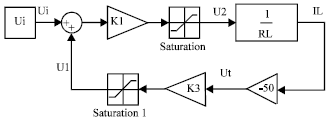 | |
| Fig. 3: | The block diagram of the feedback circuit which is made up with the current sensor |
The operational amplifier NA is an adder. After adding the control voltage Ui and feedback voltage U1, the NA control the voltage U2 of the load RL through the feedback resistance R3. The voltage Ut which is measured by the sensor N1 pass through the inverting amplifier which is made up of NB and then influence the control value. In this circuit, in order to make sure the feedback voltage and the control voltage are phase inversion, the voltage which is measured by the sensor and the current must be inversed.
In Fig. 2, suppose the amplify amount of the control voltage Ui is equal to the feedback voltage U1, that is K1 = -R3/R1 = K2 = -R3/R2. And the inverting amplify amount of the feedback circuit is K3 = -R8/R7.
Seeing that this circuit deals with the DC signal and in the system bandwidth, the operational amplifier can be simplified to a gain. At the same time, considering the saturation specification of the operational amplifier, the circuit figure is plotted in Fig. 3.
In Fig. 3, K1 = -R3/R1, RL = 35 Ω; The unit of IL is A, so -50 represents the ratio between the current sensor’s output voltage and the current value that needs measuring, the ratio K3 = -R8/R7; the unit of voltage is V. The saturation 1 is the output saturate voltage of the operational amplifier. Here, it is 15; another saturation voltage is that, when the triode is conducted completely, the voltage which is produced by the maximum current flow through the load. Here, it is 0.07x35 = 2.45.
According to the Automatic control theory, the transform function of Ui to IL is as follows:
 | (1) |
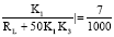
According the function this circuit must achieve, that is when the input voltage is varied between ±10 V linearly, the load’s current can vary between K 70 mA linearly, correspondingly. Then:
 | (2) |
From the above formula, we know that in order to make the ratio K1/ (RL+50 K1 K3)’s change which stirred by the load RL variation small as much as possible, the 50 K1 K3 in the denominator should be as large as possible. That is when 50 K1 K3>>RL:
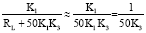 | (3) |
On the other hand, for the sake of making the circuit work in the linear area, the amplify amount cannot be designed too big. For this reason, here we choose K1 = K2 = -1. According to formula (2), we can obtain K3 ≈ 2.15. The resistance value of an actual circuit is marked in Fig. 2.
Until now, the problem seems to be solved, but after making this circuit in the real world, the 1 Hz’s oscillation emerged in this system! Moreover, the oscillation occurs when the system is in closed loop situation. If we split the circuit in U1, that is the circuit is in open loop and then the circuit works well, the problem always occurs in closed loop situation. So, it is necessary to make a detailed analysis of the circuit’s working process.
ANALYSIS OF THE PROBLEM
When the control voltage Ui is constant, if the load resistance grows bigger, then the current through the RL will become small immediately. Due to the voltage Ut measured by the current sensor and the current IL which needs measuring are phase inversion, the voltage Ut which measured by the current sensor will grow bigger afterwards. Then Ut across the inverting amplifier which is made up with operational amplifier NB output to the adder yields the voltage U1 will become small and now the control voltage does not change, then it is amplified by inverting amplifier, the voltage U2 which is produced by RL will increase. Hence, the voltage U2’s growth make the current which flow through RL increase, in this way the growth of the load resistance feeds the current reduction. This process completes in a twinkling of course.
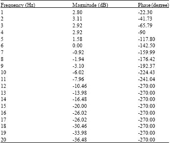
But if this process does not completes immediately, then the compensation of the U2’s change will not counteract the current change at that time. On the contrary, it will cause a bad effect. Therefore, the author considered that something in this system may have hysteresis specification, just for this reason, the voltage U2 which is produced by the load RL can not compensate the change of load’s current IL. Due to the author’s experience, the hysteresis specification brought by the operational amplifier is out of the system’s bandwidth. Tt can be ignored. But for current sensor CB0.1-CNS6B1’s specification, after the author checked its datasheet, The bandwidth specification can not be found in datasheet. Therefore, whether the hysteresis specification is brought by the current sensor is not clear. In order to confirm it, the frequency response of the current sensor with Lissajous method [14,15] was tested. The data are shown in Table 1.
Plot this sensor’s frequency response with these data in Fig. 4. Figure 4 shows that the sensor is a three order system and that its bandwidth is very narrow.
| Table 1: | The data of the current sensor’s frequency response |
 | |
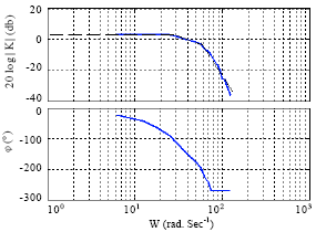 | |
| Fig. 4: | CB0.1-CNS6B1’s frequency response |
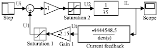 | |
| Fig. 5: | The block diagram after adding the hysteresis specification |
Using asymptote to approach the bode diagram; the sensor’s transform function is identified as follows:
 | (4) |
Due to the load resistance RL is included in this function, after removing it, the actual transform function of this sensor is:
 | (5) |
 | |
| Fig. 6: | The system simulating result after adding the hysteresis specification |
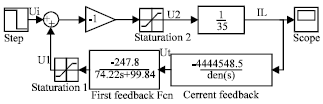 | |
| Fig. 7: | The simulation block diagram in which the feedback loop is modified |
In order to verify the author’s conjecture, adding this function to the Fig. 2, re-plot the diagram is in Fig. 5. The input step signal is 10 V.
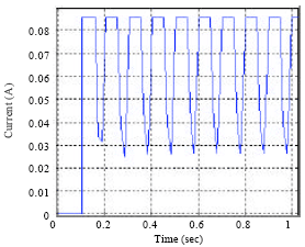
After simulating with the MATLAB, we can obtain the result as shown in Fig. 6.
From this picture, we can see that the simulation result and the real situation are nearly the same. As far as the oscillation period is concerned, the period does not equal to the actual period, which is because the current sensor’s model is not accurate.
THE SOLUTION OF THE PROBLEM
In order to solve the problem, we have to add the forward specification to compensate the hysteresis specification which is brought by the current sensor. But in doing so, we have to change the structure of this circuit, especially, we have to add forward specification in the forward channel. According to the automatic control theory, adding the hysteresis specification K/(Ts+1) in the feedback channel equals to add a zero point to the whole closed loop system and then the phase on the requiring frequency is increased.
 | |
| Fig. 8: | The system simulating result that the feedback loop is modified |
By doing so, we can just parallel a capacitor C3 to the resistance R8 in the feedback channel. The value of the parallel capacitor can be evaluated by the method.
Because of the transform function which is made up with the inverting amplifier after paralleling the capacitor is shown as follows,
 | (6) |
Then the time constant T=R8C3 and the oscillation frequency f≈1 Hz, the period is 1 sec. So in order to take effect in 1 Hz, then let R8C3 = 1 sec, C3 = 1/(R8) = 1/(247.8x103) ≈4μF Actually, we choose a 3μF’s capacitor, then the oscillation disappears. If we add the hysteresis specification to Fig. 4, the same result will be achieved. The plot modifying from the Fig. 4 is shown in Fig. 7.
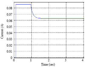
After simulating with the MATLAB, we can obtain the result given in Fig. 8:
Figure 8 shows the oscillation disappears. The current load is near to 0.07 A. At the same time, this figure also verifies the deduction which the current sensor has hysteresis specification is correct. According to the actual resistance, when the RL = 35 Ω, the ratio of the control voltage to the current is calculated from Formula (2) and it is 0.00629.
While, when the load resistance varies from 33.6 to 36.4 Ω, from Formula (2), we can obtain the whole amplify amount is between 0.00634 and 0.00623. This variation range is 0.00011, smaller than the 0.00629’s 1%., that is:
 | (7) |
CONCLUSION
This result indicates that, even if the signal in the circuit is DC, the dynamic specification of every device is very important in the feedback circuit.
ACKNOWLEDGMENTS
This study was supported by Xi’an Science Technology Bureau Fund. The authors would like to thank Pro. Zhong for his proof-reading.
REFERENCES
- Aslan, Y.L., 2005. Diagnosis of shunt faults in power distribution feeders and laterals. J. Applied Sci., 5: 1582-1588.
CrossRefDirect Link - Kilic, U., 2011. Use of wireless rumen sensors in ruminant nutrition research. Asian J. Animal Sci., 5: 46-55.
CrossRefDirect Link - Ameri, M., N. Yavari and T. Scullion, 2009. Comparison of static and dynamic backcalculation of flexible pavement layers moduli, using four software programs. Asian J. Applied Sci., 2: 197-210.
CrossRefDirect Link - Attar, H. and S. Afshar, 2010. Design of sensible biosensor for rapid detection of biocides in potable water. Asian J. Biotechnol., 2: 120-126.
CrossRefDirect Link - Rahaie, M. and S.S. Kazemi, 2010. Lectin-based biosensors: As powerful tools in bioanalytical applications. Biotechnology, 9: 428-443.
CrossRefDirect Link - Xu, C. and L. Guoyu, 2011. A Semi-physical Simulation Platform for Adaptive Front Lighting System (AFS). Inform.Technol. J., 10: 2052-2059.
CrossRefDirect Link - Lee, L.T. and C.W. Chen, 2008. Synchronizing sensor networks with pulse coupled and cluster based approaches. Inform. Technol. J., 7: 737-745.
CrossRefDirect Link - Ruan, Z. and X. Sun, 2011. An efficient data delivery mechanism by exploring multipath routes for wireless sensor networks. Inform. Technol. J., 10: 1359-1366.
Direct Link - Noaman, N.M., A.R. Ajel and A.A. Issa, 2008. Design and implementation of DHM glove using variable resistors sensors. J. Artif. Intell., 1: 44-52.
CrossRefDirect Link - Jayakumar, K., D. Yadav and B.N. Rao, 2006. A multi-layer cylindrical shell under electro-thermo-mechanical loads. Trends Applied Sci. Res., 1: 386-401.
CrossRefDirect Link - Mezghani, B., F. Tounsi, S. Smaoui, K. Haboura, S. El-Borgi, S. Choura and M. Masmoudi, 2006. Modelling and simulation of a new micromachined acoustic sensor. Trends Applied Sci. Res., 1: 456-466.
CrossRefDirect Link - Chay, T.C., S. Surif and L.Y. Heng, 2009. The behavior of immobilized cyanobacteria Anabaena torulosa as an electrochemical toxicity biosensor. Asian J. Biol. Sci., 2: 14-20.
CrossRefDirect Link