
Ryspek Usubamatov
School of Manufacturing Engineering, University Malaysia Perlis, Malaysia
Asian Journal of Scientific Research
Year: 2017 | Volume: 10 | Issue: 4 | Page No.: 380-386


ABSTRACT
Background and Objective: The gyroscope theory and effects are represented by numerous researchers, with mathematical models based on the law of kinetic energy conservation and the change in the angular momentum of a spinning rotor. The main objective of this study is to find the unknown properties of the gyroscope. Methodology: The nature of gyroscope effects is more complex and known mathematical models and theories do not match the actual motions of the gyroscope effects. Latest investigations of forces that involved in motions of a gyroscope demonstrate that there are four dynamical components, which act simultaneously and interdependently with others. These forces of classical mechanics are the centrifugal, Coriolis and inertial forces and the force generated by the change in the angular momentum of the spinning rotor. The action of mentioned forces is represented the fundamental principle of gyroscope theory. Results: The gyroscope with the external torque applied is experienced the resistance torque generated by the centrifugal and coriolis forces of the spinning rotor and the precession torque generated by the inertial forces and the change in the angular momentum. Formulated mathematical model for gyroscope motion is based on action of eight torques of about two axis and they are generated by the gyroscope internal kinetic energy. Conclusion: It is concluded that the new developed mathematical model for gyroscope validated the theoretical approach.
PDF Abstract XML References Citation
Received: February 01, 2017;
Accepted: June 13, 2017;
Published: September 15, 2017
Copyright: © 2017. This is an open access article distributed under the terms of the creative commons attribution License, which permits unrestricted use, distribution and reproduction in any medium, provided the original author and source are credited.
How to cite this article
Ryspek Usubamatov, 2017. New Analytical Approach for Finding the Gyroscope Forces and its Properties. Asian Journal of Scientific Research, 10: 380-386.
DOI: 10.3923/ajsr.2017.380.386
URL: https://scialert.net/abstract/?doi=ajsr.2017.380.386
DOI: 10.3923/ajsr.2017.380.386
URL: https://scialert.net/abstract/?doi=ajsr.2017.380.386
INTRODUCTION
The free encyclopedias and other publications represent the extensive information regarding a gyroscope. Numerous definitions of a gyroscope represent it as a device for measuring or maintaining orientation, based on the principles of angular momentum of the spinning rotor1,2. This fundamental principle of the gyroscope theory developed by famous mathematician L. Euler in 1765 in his work on the dynamics of rigid bodies. Later, Sir Isaac Newton and many other famous and outstanding scientists developed and added new interpretations for the gyroscope phenomena.
Mechanically, a gyroscope is a spinning disc in which the axle is free to assume any orientation. Today gyroscopes are represented as numerous type devices including the flight instruments, gyro-compass, the autopilot, gyroscopic stabilization and navigation instruments for ships, airplanes, space stations and satellites. The gyroscope properties are relayed in many engineering calculations of rotating parts3,4.
However, known gyroscope theory and its modifications do not match practice of the gyroscope forces and motions, i.e., no true gyroscope theory more than 200 years. This is unusual phenomenon in science and probably the authority of the famous scientists dominated over other researchers, which did not try refuting settled formulations of gyroscope theory.
The known mathematical models of the gyroscope theories are not full and not complete and cannot give true information about acting gyroscope forces and motions that called artificially gyroscope effects and phenomenon. All theories contain numerous assumptions and simplifications and explain the gyroscope effect by the change in the angular momentum that generates the precession torque5,6. However, the nature of the gyroscope physics is more complex than represented in encyclopedias, textbooks and numerous publications.
Analyses of the motions of gyroscope devices demonstrate that the external load generates internal torques based on action the centrifugal, Coriolis and common inertial forces of the spinning rotor and the change in the angular momentum. These forces are fundamental principles that lead to the gyroscope effects. The change in the angular momentum is only one component that plays not primary role in gyroscope motions. The centrifugal and Coriolis forces generate the resistance torque in change the rotor’s location. The common inertial force of the spinning rotor and the change in the angular momentum of the spinning rotor generate the precession torques. The simultaneous action of this group of torques has not been described in the physics of gyroscope effects. Based on new fundamental approaches the gyroscope effects are represented by new mathematical model7,8. This model is well matched practical results that conducted on the Super Precision Gyroscope model "Brightfusion Ltd". This paper represents new properties of gyroscope and simultaneous action of the centrifugal, Coriolis and common inertial forces and the change in the angular momentum.
MATERIALS AND METHODS
Latest investigations of the gyroscope effects demonstrate that the motions of gyroscope devices are generated by centrifugal, Coriolis and common inertial forces of the spinning rotor and by the change in the angular momentum of the spinning rotor. Short information about action of these forces and gyroscope motions are presented below.
It is known that the mass-elements of the spinning rotor experience a radial acceleration and the plane of centrifugal forces locates strictly perpendicular to the axis of the spinning rotor. The external torque applied to the gyroscope leads to change the angular location of spinning rotor plane and generates a contracting moment of the centrifugal force components. The mathematical model of the resistance torque generated by the centrifugal forces for a disc-type spinning rotoris formulated and represented in Table 18.
The tangential velocity direction of mass-elements of the spinning rotor changes continuously. The inclination of the disc of the spinning rotor generates the axial tangential velocity of mass-elements that produces the axial acceleration as well as the common inertial forces of mass-elements. The action of the common inertial forces of the mass-elements is perpendicular to the plane of the spinning rotor. These common inertial forces are causing the angular torque and the angular velocity of the rotor precession. This torque acts in the plane that perpendicular to the plane of the resistance torque that generated by the centrifugal forces. The mathematical model of the gyroscope precession torque generated by the common inertial forces of the spinning mass-elements is formulated and represented in Table 1.
The equation for the precession torque generated by the axial common inertial forces of the rotor’s spinning mass-elements is the same as the equation for the resistance torque generated by the centrifugal forces. The precession and resistance torques are generated by the same rotating masses, which accelerations are directed perpendicular to each other. The rotating mass-element of the spinning rotor and action of the external load lead to inclination of the rotor’s disc that generates the Coriolis accelerations as well as the Coriolis forces of mass-elements.
| Table 1: | Equations of internal torques acting in a gyroscope |
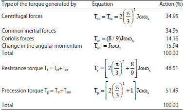 | |
These Coriolis forces are acting perpendicular to the plane of the spinning rotor and are causing the resistance torque action as the centrifugal forces. The mathematical model of the resistance torque generated by the Coriolis forces is formulated and represented in Table 1. The external torque applied to the spinning rotor generates the resistance torques based on action of the centrifugal and Coriolis forces.
The change in the angular momentum of the spinning rotor that well-described in classical mechanics generates the torque, which acts as precession torque and represented by the well-known equation (Table 1)1.
The precession torques of the gyroscope is generated by the inertial forces and the change in the angular momentum of the spinning rotor. The defined toques based on the action of the centrifugal, inertial, Coriolis forces and the change in the angular momentum are acting simultaneously and interdependently on the spinning rotor and represent the artificial term of gyroscope effects. The equations of the internal torques and percentage of acting in the gyroscope is represented in Table 1.
where Tct is a resistance torque generated by the centrifugal forces of the spinning mass-elements; J is a rotor’s mass moment of inertia, ω is an angular velocity of the spinning rotor, ωx is an angular velocity of precession of a spinning rotor about the axis ox, Tin is a precession torque generated by the inertial forces, Tcr is a resistance torque created by the Coriolis forces, Ta.m is a torque generated by the change of angular momentum, other parameters are as specified above.
The analysis of equations (Table 1) demonstrates that the internal resistance and precession torques are the result of the action of the external torque applied to a gyroscope. The gyroscope internal torques depends on the angular momentum J of rotating mass, the angular velocity ω of the spinning rotor and on the angular velocity of the precession ωx. Absence of the external torque means that the angular velocity of precession ωx = 0. Then, the gyroscope internal torques has disappeared, which is a natural result.
RESULTS
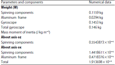
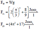
The action of the centrifugal, common inertial and Coriolis forces and generated by the change in the angular momentum of the spinning rotor is validated by practical tests of the gyroscope with one side support. The action of internal torques is displayed on the motion of the gyroscope about axis ox. The test of the angular velocities of gyroscope precessions was conducted on the base of the Supper Precision Gyroscope "Brightfusion LTD" (Fig. 1), which the technical data are represented in Table 2. The velocity of the spinning rotor measured by the Optical Multimeter Tachoprobe Model 2108/LSR Compact Instrument Ltd. with range of measurement 0-60,000.00 rpm. The drop of the revolution velocity for the spinning rotor is represented 66.6 rps. For simplicity of calculations, the tests of the gyroscope motions are conducted for the location of the gyroscope axis that close horizontal with deviations ±100. The angular measurements of the location for the gyroscope axis conducted optically and by the angular template with accuracy ±1.00. The technical parameters of the gyroscope components were calculated for the equations of the gyroscope torques (Table 1) and represented in Table 2. The gyroscope with one side free support is suspended on the cord and its weight generates the external torque T that results the gyroscope precessions about the point o of the support, which is the centre of coordinate system Σoxyz (Fig. 1). This type of the tests for the gyroscope with one side free support enables to rotate the gyroscope about two axes ox and oy.
Based on the initial data of the gyroscope is calculated the magnitudes of internal torques. The resistance and precession torques that generated by the centrifugal and inertial forces are represented by the following result:
![]()
The resistance torque that generated by the Coriolis forces is represented the following result:
![]()
where, all parameters are specified above.
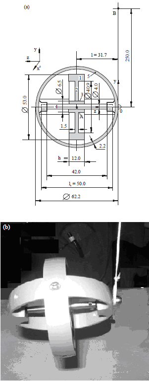 | |
| Fig. 1(a-b): | Supper precision gyroscope "Brightfusion LTD" |
The tests of the gyroscope with one side free support on motions are conducted at the horizontal location of the gyroscope axis. This condition simplifies measurements and gives more accurate result in tests and calculations. The weight of the gyroscope and torques generated by centrifugal, inertial and Coriolis forces and generated by the change of the angular momentum of the spinning rotor should react on the one side free support of the gyroscope.
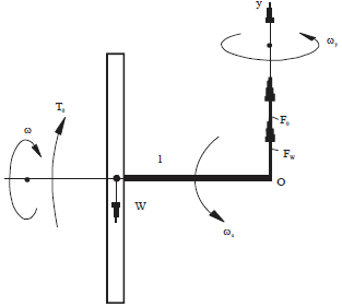 | |
| Fig. 2: | Reactive forces acting on the one side free support of the gyroscope |
| Table 2: | Technical data of super precision gyroscope, "Brightfusion LTD" |
 | |
The reactions all these force components are represented in Fig. 2 according to the rules of classical mechanics.
The equations of reactive forces on the free support along the axis oy are based on action of the weight resistance and precession torques (Fi = Ti/l) of the gyroscope are represented by the following Eq. 1 7,8:
 | (1) |
where, all parameters are as specified and calculated above.
The tests of the gyroscope with one side free support demonstrate the gyroscope precession velocities about axis ox, ωx = 0.0131371 rad/s and about axis oy, ωy = 0.7419646 rad/s. Substituting defined parameters that calculated and represented in Table 2 into Eq. 1 and transforming yield the following results in Fig. 2.
The total torque acting on the gyroscope free support O is as follows:
![]()
Substituting defined parameters and transforming yields the following result:
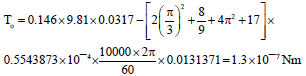
The magnitude of the total torque acting on the gyroscope free support is small. The reactive force acting on the support is as follows:
![]()
The magnitude of the reactive force acting on the gyroscope free support is also small, this is the reason that practical test of the forces acting on the gyroscope support demonstrates the action of its weight. Practical test of the gyroscope with one side free support and measurement of the forces action on the cord (along the axis oy) was conducted by the stand that represented in Fig. 3. The forces were measured by the Compact Digital Scale of the model Taylor TE10FT 5.0 kg with increments 1.0 gr. Figure 3a and b represent the photography and the sketch of the stand with the digital scale and the gyroscope with one side support. The gyroscope is suspended on the flexible cord that connected with the platform of the scale. The tests conducted for the gyroscope which axis of the spinning rotor was at horizontal location.
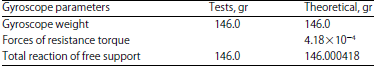
The results of theoretical calculations by Eq. 1 and measurements of practical tests of the acting forces are represented in Table 3. Results of practical tests and measurement of the forces acting on the cord of free support demonstrate that the force weight of the gyroscope is equal to the reactive force of the support for the gyroscope with horizontal location of its axis. The reactive forces that generated by the centrifugal, inertial, Coriolis forces and by the change of the angular momentum of the spinning rotor do not act on the free support of the cord or along the axis oy. At the first sight these phenomena contradict to the rules of the classical mechanics. However, these gyroscope phenomena can be explained by the following reasons:
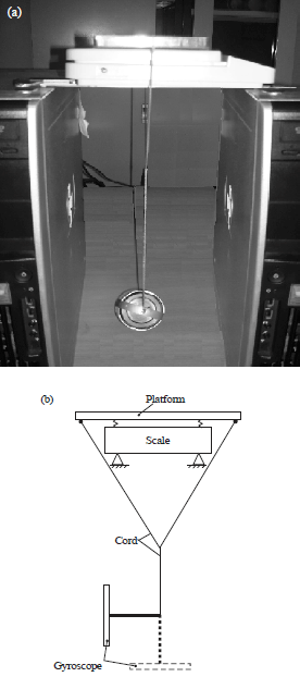 | |
| Fig. 3(a-b): | Measurement of the acting forces on the gyroscope with one side free support |
| Table 3: | Experimental and theoretical results of the forces acting on a gyroscope |
 | |
| • | The internal resistance torques generated by the centrifugal, inertial, Coriolis forces and by the change in the angular momentum is the reaction on action of the applied or load torque |
| • | The magnitude of the resistance torques that acting about the axis ox cannot exceed the magnitude of the load torque that can be external or internal one. It means this resistance torques is restraint torques only and do not generate the big reactive force on the support |
Described phenomena of the action the gyroscope internal resistance torques is new unknown property of the gyroscope that should be taken into account for the calculations of the gyroscope forces and motions at different mechanisms and devices. Gyroscope internal resistance torques does not generate the sensitive reaction on the support along the axis oy and can be neglected. This statement does not contradict to the rules of the classical mechanics that deal with real forces and moments. However, in the gyroscope are acting the internal forces that appearing only in process of motions and disappearing in case of absent one. The nature of these phenomena of the action the internal forces in mechanical systems did not describe in science.
The obtained results, which representing new phenomena, can be spread on the action of the torques are acting about the axis oy that are load torques and resistance torques. In this case, the resistance torques is restraint torques also that does not generate big forces acting on the support. It is proven by the magnitudes of the load torques and resistance torques. Substituting the magnitudes of the angular velocities into equations of this torques, the magnitude of the resistance torque will be many times larger than the magnitude of the load torque. Theoretically, it leads to rotation of the gyroscope in opposite direction that the load torque acts. Practically, the gyroscope rotates in direction of the load torque. This is proving that resistance torque in the gyroscope is restraint torque. As a result, the gyroscope gets high angular velocity about the axis oy under action of the inertial torque and the change in the angular momentum that represents the load torque.
The action of the internal torques acting about the axis oy for the gyroscope suspended on the flexible cord cannot be measured due to free motion of the cord at the horizontal plane xoz. However, the action of these torques are measured for the gyroscope with fixed supports.
The test of the gyroscope with fixed support about axis ox, if the gyroscope rotation about axis oy is blocked or inhibiting, demonstrates other phenomena. These phenomena are represented by the gyroscope rotation about the axis ox that is carrying out with high angular velocity. This velocity is larger than velocity of the gyroscope rotation about two axes. Analysis of torques acting on the gyroscope enables to explain this phenomenon by the following reason. In case of the blocking the gyroscope rotation about axis oy the following torques is involved in process:
| • | The torque generated by the inertial forces and the change in the angular momentum of the spinning rotor with the precession about the axis ox, activates the reactive counter torque from the support |
| • | Reactive counter torque about the axis oy leads to deactivation of the resistance torque generated by the centrifugal and Coriolis forces about the axis ox and to deactivation of the resistance torque generated by the inertial forces and the change in the angular momentum about the axis oy |
| • | Deactivation of all resistance torques about the axis ox leads to increasing the angular velocity of the gyroscope precession about the axis ox |
| • | Inhibiting the gyroscope rotation about the axis oy leads to proportional decreasing of the action the resistance torques that are involved in processes and to proportional increasing the angular velocity of gyroscope precession about the axis ox |
DISCUSSION
The load torque applied to the gyroscope leads to an angular velocity of precessions and generates the torques based on action of the centrifugal, common inertial, Coriolis forces and the changes in the angular momentum of the spinning rotor. Based on the action of these torques is formulated the mathematical models for the resistant and precession torques about the axis ox an oy at accepted systems of coordinates. These torques are generated by the gyroscope weight, which suspended by one side support, demonstrate that torques depend on the mass moment of inertia and angular velocity of the spinning rotor, as well as on the angular velocity of its precession. The new analytical approach to gyroscopic problems demonstrates that centrifugal, common inertial and Coriolis forces of the mass-elements for the spinning rotor are really active physical components as it’s the change in the angular momentum. These forces generate the torques that act simultaneously, interdependently and resulting in the resistance and precession torques, respectively7. Experimental tests and results of the gyroscope torques that conducted for the gyroscope suspended on one side support demonstrates that resistance torque does not generate the sensitive reactive force of the support and can be neglected. The magnitude of the resistance torque does not exceed the magnitude of the load torque and inertial torque. Blocking motions of the gyroscope about one axis deactivate the resistance torques acting about other axes.
The gyroscope theory in classical mechanics is one of the most complex and intricate in terms of analytical solutions8. The known mathematical models for the gyroscope theory are mainly based on the actions of the load torque and the change in the angular momentum of the spinning rotor. The known gyroscope theory does not give correct answer on numerous practical problems. This is the reason that the gyroscope still attracts researchers that trying to find true theory and give correct mathematical models for the gyroscope effects. The known gyroscope theory and mathematical models do not consider the action of the internal centrifugal, common inertial and Coriolis forces of the rotating mass of spinning rotor, which play a critical role as well the change in the angular momentum9. The new analytical approach demonstrates that the centrifugal and Coriolis forces of the spinning rotor resist any inclination of the rotor’s axis and generate the resistance torques. The axial common inertial forces and the change in the angular momentum of the spinning rotor generate the precession torque.
CONCLUSION
In this study, analytical approach for the gyroscope effects, describes and demonstrates the new gyroscope properties. In the results the mathematical models for the gyroscope torques demonstrated that the spawned steady myth of the gyroscope mystery should be removed from the scientific terminology. However, new mathematical models for the new internal torques discover new gyroscope properties and enable to solve gyroscope problems in engineering. These circumstances are represented new challenges and attract new researchers to describe gyroscope effects by new analytical approach based on action of the known forces in classical mechanics.
SIGNIFICANCE STATEMENT
This study discover the unknown new properties of the gyroscope and formulated the mathematical model for gyroscope motion based on action of eight torques of about two axis generated by the gyroscope internal kinetic energy.
ACKNOWLEDGEMENT
The author would like to thank the University Malaysia Perlis for helping in this research and to express thanks to the governing body for its excellent strategic policy in scientific research.
REFERENCES
- Kang, J., 2009. Squeal analysis of gyroscopic disc brake system based on finite element method. Int. J. Mech. Sci., 51: 284-294.
CrossRefDirect Link - Quinn, T.J. and A. Picard, 1990. The mass of spinning rotors: No dependence on speed or sense of rotation. Nature, 343: 732-735.
Direct Link - Zhang, Z., J. Sun and K. Wu, 2005. Error analysis and test study of fiber optic gyroscope North-finder. Proc. SPIE., 5634: 611-618.
CrossRefDirect Link - Usubamatov, R., 2014. Properties of gyroscope motion about one axis. Int. J. Advancements Mech. Aeronaut. Eng., 2: 39-44.
Direct Link - Usubamatov, R., 2015. Mathematical model for gyroscope effects. AIP Conf. Proc., 1660: 825-826.
CrossRef - Lang, G.M., N. Bhuvanesh, J.H. Reibenspies and J.A. Gladysz, 2016. Syntheses, reactivity, structures and dynamic properties of gyroscope-like iron carbonyl complexes based on dibridgehead diarsine cages. Organometallics, 35: 2873-2889.
CrossRefDirect Link