
Ai Rong Chen
Department of Bridge Engineering, Tongji University, People’s Republic of China
S.Y.K. Al-Darzi
Department of Civil Engineering, College of Engineering, University of Mosul, Iraq
Asian Journal of Applied Sciences
Year: 2009 | Volume: 2 | Issue: 4 | Page No.: 385-393


ABSTRACT
The connection between steel and concrete aimed to be enhanced through investigating and developing the composite action affects on overall behavior of composite bridge. Among different types of connectors available today, the perfobond connector is suggested to enhance the connection properties. The push-out test is used to investigate the resistance capacity of the available regular perfobond connector. Several finite element models are developed and verified to simulate the push-out test specimen, shell element, solid element and bar element with both geometric and material nonlinearities. The verified finite element model is then used to test the applicability of the newly suggested connectors, replacing circular holes in the regular perfobond connectors by triangular one. The resistance capacities predicted for the newly suggested shapes seem to be close to that predicted from the regular perfobond connector. The results indicate that the new connector is applicable and supposed to be more reliable in steel-concrete composite structure, predicting more integrity between concrete. A recommendation on performing more studies on the newly suggested connectors are withdrawn due to the sensitivity of the connector to the dimension and shape of hole.
PDF Abstract XML References Citation
How to cite this article
Ai Rong Chen and S.Y.K. Al-Darzi, 2009. New Perfobond Rib Connector Shapes. Asian Journal of Applied Sciences, 2: 385-393.
DOI: 10.3923/ajaps.2009.385.393
URL: https://scialert.net/abstract/?doi=ajaps.2009.385.393
DOI: 10.3923/ajaps.2009.385.393
URL: https://scialert.net/abstract/?doi=ajaps.2009.385.393
INTRODUCTION
Design of steel-concrete composite structures in general and composite bridges in particular including the design of both steel beam and concrete slab. Connection between the steel beam and concrete deck, is usually conducted through different types of connectors, such as stud, channel, spiral, tendon and perfobond connectors (Salmon and Johanson, 1990; Liu, 2004). Development of the steel concrete composite bridge might be conducted through improving concrete slab and steel beam connection, which allows the composite action to be more effective. The design equations used to calculate the shear resistance of the shear connector, such as stud shear connector currently included in ANSI/AISC 360-05 [ANSI/AISC 360-05, 2005] standard, mainly based on experimental investigations of push-out specimens, while the Chinese code stated that other types of connectors, means other than those stated on code, may be used on reliable basis. This allow for suggesting, testing and using a suitable new types of connectors.
In the last decades, the perfobond rib connector was suggested as a new type of connector, which is clearly enhanced the connection between concrete slab and steel beam, using push-out test specimens and numerical analysis to establish their shear resisting equation, noting that, the transverse reinforcement are mainly affect on their resisting capacity (Oguejiofor and Hosain, 1997). Therefore, allowing for more transverse reinforcement to pass through the rib holes are expected to enhance the interaction between the concrete slab and connector. A triangle shape of the rib holes are suggested by Al-Darzi and Chen (2006). The applicability of the newly suggested shape is checked by comparing the push-out test results obtained by finite element model with the resistance capacity of the available regular perfobond connector obtained by experiments and numerical methods. In the present study, the newly suggested shape of perfobond connector with an equivalent hole area are then simulated using the verified finite element model. Four different shapes of newly suggested connectors have been modeled to investigate the applicability of the triangular hole shape.
The main objectives of the present study are to conduct numerical study of push-out specimens using the finite element analysis, verifying the accuracy of finite element model and the applicability of the model to simulate the push-out test by comparing the numerical results with the experiments, and using the verified finite element model to model the push-out test with triangular hole shape perfobond connector.
The perfobond shear connector is firstly developed in Germany (1987), which is a steel plate with holes positioned vertically and welded to steel beam flange, steel reinforcement bars are placed through the rib holes, then concrete placed around and through connectors, as shown in Fig. 1. An investigation was carried out by Oguejiofor and Hosain (1997) on modeling the push-out test using such type by finite element aiming to predict a numerical expression of the resisting capacity for perfobond shear connectors (Oguejiofor and Hosain, 1997). The results of push tests with perforate shear connector were also presented aiming to develop the basic shear resistance suitable for concrete deck plates with precast concrete slab used as a shuttering (Studnicka et al., 2000). The experimental tests were carried out using perfobond connectors and lightweight concrete, describing the connection behavior, measuring slip between steel profile and concrete slab, defining the connection ductility and considering the concrete strength, reinforcement disposition and perfobond rib existence and spacing of holes (Valente and Cruz, 2004). A test program conducted for steel-concrete composite bridge decks with perfobond rib shear connectors was presented for composite deck consists of profiled steel sheeting, perfobond ribs, steel reinforcements and concrete. The push-out, full-scale flexural and deck-to-girder connection tests for each deck profile were conducted. The results shown that the perfobond ribs can be effectively used for shear connection in the steel-concrete composite bridge decks. (Kim and Jeong, 2006).
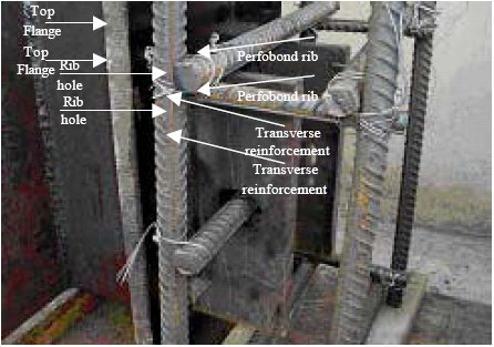 | |
| Fig. 1: | Perfobond shear connector used in push-out test |
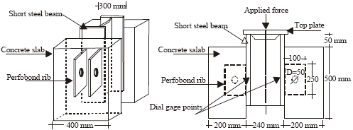 | |
| Fig. 2: | Typical push-out specimen with perfobond connector (a) Isometric view and (b) Side view |
A push-out specimen consists of a short steel beam section held in a vertical position by two identical reinforced concrete slabs attached to the beam flanges by shear connectors, as shown in Fig. 2. The overall system is subjected to vertical load, using hydraulic jack, producing shear load along the interface between the concrete slab and the beam flange on both sides. Top plate is used to ensure that the load applied uniformly. The push-out test with four different groups, with a concrete compressive strength fcu= 54.60 MPa, steel yielding stress Fyb = 345 MPa and reinforcement steel yielding stress Fyr = 345 MPa were conducted, measuring the relative displacement between steel and concrete with the applied load to failure of each specimen. The load-slip curves were drawn for each specimen. The results of NP2 group gives best resisting capacity which therefore adopted to compare with after modeling the test by computer to study the effect of a number of parameters on the performance of the connector, instead of making a series of push out tests (Liu, 2004). Where, it is familiar to use finite element method to conduct a parametric study and to investigate the effect of different parameters on the resisting capacity of shear connector (Oguejiofor and Hosain, 1997).
NUMERICAL ANALYSIS
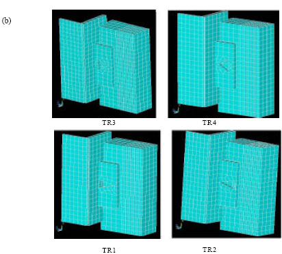
The finite element models are developed to predict the capacity of shear connectors. Several finite element models are tested with different level of modeling and different mesh size using ANSYS software. The final model is verified by measuring the displacement at the same points were the dial gage fixed in experiments with the applied load, drawing the load-slip curve. Due to the advantage of symmetry and for simplifying the calculating process, only quarter of the push-out test model is used in finite element analysis.
The three-dimensional reinforced concrete solid element (Solid 65) defined by eight nodal points, shown in Fig. 3a, is used. Whereas, each nodal point has three degrees of freedom, translations in x, y and z directions, having one solid concrete material and up to three reinforcing bar materials, with concrete capability of cracking in tension and crushing in compression in three orthogonal directions, as well as incorporating plastic and creep behavior. A smeared reinforcement can be used throughout the element achieving the bar directional orientation through user-defined angles, using an iterative solution for nonlinear analysis and the stiffness matrix is reformulated after each iteration. For each load step to be judged as converged a three convergence criteria have to be satisfied, these are the bilinear elements status, large deflection and plasticity criteria. The three-dimensional shell element (Shell 43) shown in Fig. 3b, is defined by four nodal points with six translational degrees of freedom per node, four nodal thicknesses, material direction angle and the orthotropic material properties. This element has in-plane and out-of-plane stiffness, this element was adopted to model the steel beam section and perfobond rib connector.
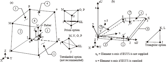 | |
| Fig. 3: | The ANSYS elements used to simulate push-out specimen (a) Solid 65 geometry and (b) Shell 43 geometry |
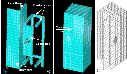 | |
| Fig. 4: | Finite element modeling of push-out specimen with perfobond connector. (a) Steel beam, reinforcement and quarter concrete slab and (b) overall quarter model |
The three dimensional spar element (Link 8) is used to model the reinforcement, which is a uniaxial tension-compression element with three degrees of freedom at each node: translations in the nodal x, y and z directions. As in a pin-jointed structure, no bending of the element is considered. Plasticity, creep, swelling, stress stiffening and large deflection capabilities are included (Kohnke, 2001). The finite element assembly of the push-out test specimen modeling is shown in Fig. 4a and b.
The nonlinear elastic option (MELAS) adopted to be used for concrete material, which requires the input of a uniaxial stress-strain curve for concrete. The typical stress-strain curve for concrete is linearly elastic up to 30% of the maximum compressive strength fc’. This was used to establish the first point of the stress-strain curve, where, fc = fc’/3 and the corresponding strain is defined by ε = fc’/Ec, where, Ec is the Young’s modulus of elasticity for concrete. The other points in the stress-strain curve are established by using the numerical expressions given by Oguejiofor and Hosain (1997). The bilinear kinematic hardeni1ng (BKIN) is adopted to be used for steel beam section, perfobond ribs and reinforcements.
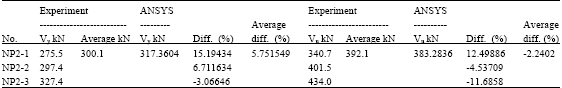
| Table 1: | Yield and ultimate capacity of push-out specimen from experiments and ANSYS |
 | |
| Table 2: | Relative displacement of push-out specimen from experiments and ANSYS |
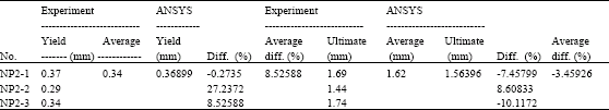 | |
| Vy is the yielding force in kN and Vu is the ultimate force in kN | |
The material behavior is described by a bilinear total stress-total strain curve starting at the origin and with positive stress and strain values. The initial slope of the curve is taken as the elastic modulus of the material. At the specified yield stress, the curve continues along the second slope defined by the tangent modulus Kohnke (2001). A uniformly distributed load applied at the top of beam flanges, all the nodes at the top steel section are constraints to have a uniform displacement in the load direction, whereas, in the actual test the load was applied through thick steel plate. Similarly, all nodes at the bottom of concrete slabs are constrained. Coincident nodes at the junction of perfobond rib elements and steel flange and web elements and at connector and concrete slab were merged to simulate the rigid connection of these elements. Merging of nodes replaces all the nodes that lie at the same coordinate location with only one node and the lowest node number of all the nodes merged is retained. Also, coincident concrete and steel flange element nodes were coupled in both x and z directions. Similar to the actual test, the load are applied slowly in several sub-step to failure, a constant steps of 3 kN is used, 140 iteration are allowed for each load step, a full Newton-Raphson method is applied and the solution automatically proceeded to the next load step if convergence is achieved after only a few iterations. Each analysis was continued until the solution no longer converged, at which point the ultimate load was deemed to have been attained.
Table 1 shows the ultimate capacity of push-out specimens as obtained from experiments and ANSYS models at yield and ultimate stages and Table 2 shows the relative displacements of push-out specimens as obtained from experiments and ANSYS models at yield and ultimate stages. It was observed from Table 1 that, on the average, the shear capacity values predicted from ANSYS are approximately 5.75% at yielding stage greater than the experimental results and 2.24% at ultimate stage lower than the experimental results. It was also observed from Table 2 that the average relative displacement values predicted from ANSYS are approximately 8.53% at yielding stage greater than the experimental results and 3.46% at ultimate stage lower than the experimental results. The results obtained from this study are considered to be reasonable. Since, the finite element model was found to provide reasonable results, it was used to generate more numerical data using the newly suggested perfobond connector shapes.
THE APPLICATION OF TRIANGULAR HOLE PERFOBOND CONNECTOR RIB
The triangular hole shape of perfobond connector are suggested to be used as a new form of perfobond connector, aiming to improve the interaction between concrete and steel beam (Al-Darzi and Chen, 2006). It is supposed that the triangular hole would increase the interaction between the connector and concrete, whereas, such shape allowed for more reinforcement to pass through the holes and increasing concrete connector interaction area.
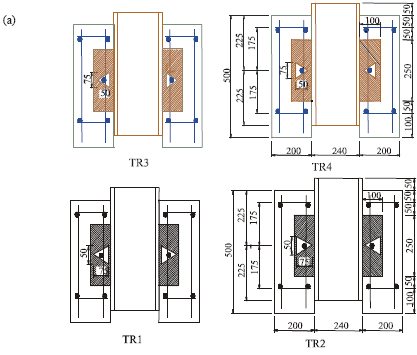 | |
| Fig. 5: | Geometry of the newly suggested triangular hole perfobond connector specimen. (a) Connector details and (b) ANSYS modeling |
Therefore, the finite element model is used to conduct an investigation using the triangular hole perfobond connector. A finite element models are used to simulate the push-out specimen with triangular hole perfobond connector having triangle hole area approximately equal to the circular area used in regular one. Four different shapes of connectors, namely TR1, TR2, TR3 and TR4, shown in Fig. 5a and b are modeled using the same regular perfobond rib model geometry, properties and loads.
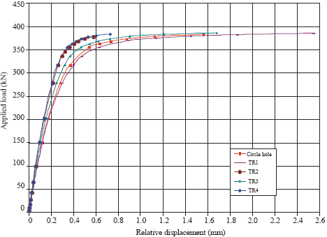 | |
| Fig. 6: | Load-displacement curve of the newly suggested triangular hole perfobond connector compared with the circle hole shape specimen |
| Table 3: | Ultimate capacities and displacements for circular and triangular hole connectors |
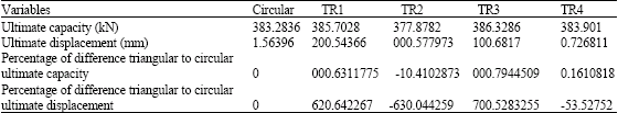 | |
The finite element analysis are then conducted and the load-displacement curves for the circle hole shape (regular) rib connector and the new four connectors are plotted as shown in Fig. 6. Also, the ultimate capacities and displacements of the circular and triangular hole shape connectors are stated in Table 3.
DISCUSSION
Figure 6 shows that the results of all new triangular hole shape models are compatible with the circular one. The resisting capacity for models TR1 and TR3 are greater than the circular one with an excessive displacement appears with TR1 model and approximately equal with model TR3. While, model TR2 give a relatively small resisting capacity comparing with circular hole model with small displacement and model TR4 give an approximately the same resisting capacity comparing with the circular one with small relative displacement.
Table 3 shows the ultimate capacities and displacements of the circular and triangular hole shape connectors. Two main parameters were considered, the width and height of triangle hole and the position of triangle’s head. It can be seen that, the main parameter affects on resisting capacity of the connector is the position of triangle hole’s head. Whereas, inverting the position of triangle head as in models TR1 and TR2 reduce the resisting capacity of about 2% but at the same time reducing the relative displacement to 77%, as well as with models TR3 and TR4 reducing the resisting capacity and relative displacement to 0.6 and 57%, respectively. It can be seen clearly that using model TR3 and TR4 give an acceptable resisting capacity with small displacement, which means that more rigid connection can be produced by using such type of connector.
CONCLUSIONS AND RECOMMENDATIONS
From the earlier numerical study and according to the predicted results, it can be concluded that:
| • | The perfobond connector with triangular hole shape is applicable and give an acceptable resisting capacity |
| • | The newly suggested type is sensitive to the position of triangle’s head and width to depth ratios |
| • | Using such new type of connector with hole’s head near flange would produce better resisting capacity with small displacement, this would be useful in decreasing the amount of relative slip between concrete slab and steel beam, which means that more interaction can be gained in composite steel-concrete bridge |
| • | The use of such type of connector would expect to enhance the connecting performance by allowing to more reinforcement to pass through rib holes. In fact, the aim of using such types focusing on using two layer of transverse reinforcement passing through rib holes representing the main slab reinforcement used in moment resisting |
| Moreover, several recommendation can be withdrawn as: |
| • | More detailed study need to be performed to investigate the behavior of the newly suggested type of connector, through conducting experiments and more numerical analysis |
| • | More parametric study need to be performed to investigate the effect of several parameters such as the depth to width ration, hole area, transverse reinforcement pass through connector’s hole and depth and width of connector on resisting capacity and displacement of push out test specimen |
| • | More investigations need to be performed on the applicability of new connector’s type on designing and constructing composite steel-concrete bridges through testing composite beam with the new connectors conducting more numerical analysis |
ACKNOWLEDGMENT
This research was supported by Chinese Scholarship Council and Tongji University, Naning Bridge Project and Mosul University.
NOMENCLATURE
| fc’ | : | Concrete cylinder compressive strength |
| fcu | : | Concrete cube compressive strength |
| Fyb | : | Steel yielding stress |
| Fyr | : | Reinforcement steel yielding stress |
| ε | : | Strain |
| E | : | Modulus of elasticity |
| Vy | : | Yielding force |
| Vu | : | Ultimate force |
REFERENCES
- Al-Darzi, S.Y.K. and A. Chen, 2006. Development of hybrid bridges: State of arts and conceptual design. J. Applied Sci., 6: 2799-2803.
CrossRefDirect Link - Kim, H.Y. and Y.J. Jeong, 2006. Experimental investigation on behaviour of steel-concrete composite bridge decks with perfobond ribs. J. Construct. Steel Res., 62: 463-471.
CrossRef - Oguejiofor, E.C. and M.U. Hosain, 1997. Numerical analysis of push-out specimens with perfobond rib connectors. J. Comput. Struct., 62: 617-624.
CrossRef - Studnicka, J., J. Machacek, A. Krpata and M. Svitakova, 2000. Perforated shear connector for composite steel and concrete beams. Proceedings of the Composite Construction Conference, May 28-June 2, 2000, Banff, pp: 367-378.
CrossRef - Valente, I. and P.J.S. Cruz, 2004. Experimental analysis of Perfobond shear connection between steel and lightweight concrete. J. Construct. Steel Res., 60: 465-479.
CrossRef