ABSTRACT
In this study, a method for dynamic modeling of a five-link seven degree of freedom (DOF) biped robot has been developed. The method, which is based on neural networks, considerably reduces the complexities in solving the dynamic model equations of the biped robot. Seven neural networks have been synthesized in order for modeling of the seven DOF of the robot being the coordinates of the torso center of mass, the torso angle and the left and right knee and thigh angles. In order for generating data for neural network training, the robot dynamics while walking on a non-smooth two-dimensional surface has been has been considered. The input sets of the trained neural networks consist of four applied torques in addition to the last sample time value of each output. These fed-back outputs not only account for the system second order dynamics but also help on compensating the surface non-smoothness very well. Evaluation results are representative of high performance and much lower complexity of the trained networks with respect to the nonlinear second order robot dynamics model.
PDF Abstract XML References Citation
How to cite this article
DOI: 10.3923/jas.2008.3612.3620
URL: https://scialert.net/abstract/?doi=jas.2008.3612.3620
INTRODUCTION
With the recent development of advanced humanoid robots, legged robots have become one of the main topics in advanced robotic research (Hitomi et al., 2006; Mousavi et al., 2008; Mousavi et al., 2007). Projects addressing legged robots usually study the stability and mobility of these mechanisms in a range of environmental conditions for applications where wheeled robots are unsuitable. One of the main interests in this area is getting the robot to remain stable as it walks in a straight line, especially when the walking surface is not necessarily smooth (Lope et al., 2003). There are two approaches for achieving this purpose. The first, called static balance, aims to maintain the projection of the Center of Masses (COM) of the robot inside the area inscribed by the feet that are in contact with the ground. The COM represents the unique point in an object or system which can be used to describe the system`s response to external forces and torques. The second method, also referred to as dynamic balance, uses the Zero Moment Point (ZMP), which is defined as the point on the ground around which the sum of all the moments of the active forces equal zero (Lope, 2003; Vukobratovic et al., 1990). If the ZMP is within the convex hull of all contact points between the feet and the ground, the biped robot is stable and will not fall over (Huang et al., 2001; Furuta et al., 2001). Due to their multivariable, high order, nonlinear and time-variant dynamics modeling and control of biped robots is not a straight forward task and so is an open problem, yet (Mousavi et al., 2008; Mousavi and Bagheri, 2007). While precise control strategies need to employ the robot dynamics in on line control strategies (Kong et al., 2008; Zhou and Meng, 2003; Hurmuzlu et al., 2004; Beigzadeh et al., 2008; Hitomi et al., 2006), solving highly complex and nonlinear dynamics equations of the biped robot model is not computationally-efficient (Kong et al., 2008). On the other hand, solving the control problems regardless of the robot dynamics may degrade the robot control performance, especially when there exist some kinds of disturbances such as ground surface un-smoothness.
Based on the above discussions, development of an easy-to-use dynamic model which considers both the nonlinear properties of the biped robot as well as surface model seems very helpful. Therefore, in this study, dynamic modeling of a five-link robot in effect of joint torques and surface non-smoothness has been considered. Regarding the high performance of neural networks in modeling nonlinear complex systems behavior, here they have been employed as the modeling tool. For this purpose, proper model inputs has been chosen via a systematic approach and then the underlying neural networks for modeling the position of the center of mass of the torso and the robot joint angles being the torso angle and the left and right knee and thigh angles has been trained. In order for generating data for neural network training, the robot dynamics while walking on a non-smooth two-dimensional surface has been has been considered. The input sets of the trained neural networks consist of four applied torques in addition to the last sample time value of each output. These fed-back outputs not only account for the system second order dynamics but also help on compensating the surface non-smoothness very well. So, the objective of the study is the development of method for dynamic modeling who is representative of high performance and much lower complexity of the trained networks with respect to the nonlinear second order robot dynamics model.
MATERIALS AND METHODS
A. Five-Link Biped Robot Dynamic Model
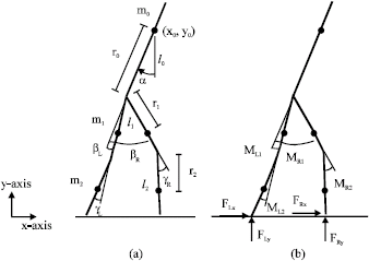
Biped robot dynamics: The biped robot considered in this study is a two-dimensional biped consists of five links which are connected with frictionless joints (Haavisto and Hyötyniemi, 2004). The identical legs have knee joints between the shank and thigh parts and one rigid body forms the torso. Figure 1a shows the model structure and variables used. As the system can move freely in the x-y-plane and contains five links, it has seven degrees of freedom. The corresponding seven coordinates are selected according to Fig. 1a as:
![]() | (1) |
The coordinates (x0, y0) stands for the position of the center of mass of the torso and the rest of the coordinates describe the joint angles as:
• | α | : | Torso angle |
• | βL and βR | : | Left and right thigh angles |
• | γL and γR | : | Left and right knee angles |
The link lengths are denoted as (l0, l1, l2) and masses as (m0, m1, m2). The centers of mass of the links are located at the distances (r0, r1, r2) from the corresponding joints. The model is actuated with four moments:
M = [ML1 MR1 ML2 MR2]T | (2) |
Two of them acting between the torso and both thighs and two at the knee joints (Fig. 1b). The walking surface is modeled using external forces:
F = [FLx FRy FLx FRy]T | (3) |
that affect the both leg tips. When the leg should touch the ground, the corresponding forces are switched on to support the leg. As the leg rises, the forces are zeroed.
![]() | |
Fig. 1: | (a) Biped model coordinates and constants, (x0, y0): the position of the center of mass of the torso, α: torso angle, βL and βR: left and right thigh angles, γL and γR: left and right knee angles,(l0, l1, l2): the link lengths, (m0, m1, m2): the link masses and (r0, r1, r2): the distances of centers of mass of the links from the corresponding joints and (b) external forces, M = [ML1 MR1 ML2 MR2]T: actuating moments and F = [FLx FRy FLx FRy]T: walking surface external forces (Haavisto and Hyötyniemi, 2004) |
Using Lagrangian mechanics, the dynamic equations for the biped system can be derived as:
![]() | (4) |
Here, A(q) ε 7x7 is the inertia matrix and
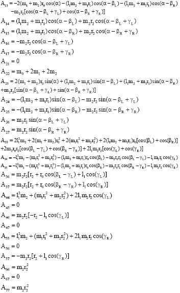
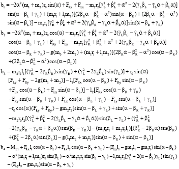
is a vector containing the right hand sides of the seven partial differential equations. The closed form formulas for both A and b are listed in Appendix A (Haavisto and Hyötyniemi, 2004).
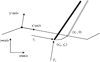
Ground contact forces model: The ground surface is modeled as a set of points (x, y) that are connected with straight lines. Figure 2 shows a sketch of one leg in touch with the ground. A new coordinate system (x`, y`) is now defined so that its origin is the next ground point to the negative x direction of the leg tip. The axis x` is aligned tangential to the ground surface and y` equals the surface normal direction as shown in Fig. 2. When the leg tip touches the ground at the point , normal and tangential forces are applied to it. The normal force dynamic is calculated as (Haavisto and Hyötyniemi, 2004):
![]() | (5) |
where, is the current (negative) leg tip in y` coordinate, ky the ground normal elastic constant and by the normal damping ratio. Additionally the normal force is limited to positive values to prevent the leg sticking to the ground.
![]() | |
Fig. 2: | The leg tip touches the ground in point ![]() ![]() |
In the tangential direction the force Ft acting is caused by friction. The static friction force is determined similar to the normal force calculation (Haavisto and Hyötyniemi, 2004). Now the nominal value, however, is the initial touching point :
![]() | (6) |
where, kx and bx are the ground tangential properties. If the required force exceeds the maximum static friction force
Ft,max = μsFn | (7) |
μs being the static friction coefficient, the leg starts to slide. In that case the tangential force is:
Ft = μkFn | (8) |
where, μk is the kinetic friction coefficient. The stored value of is continuously set to the corresponding leg tip
position during the sliding. After the normal and tangential forces are computed, they need to be projected to the original coordinate system (x, y) to attain the dynamic model input forces of Eq. 3.
B. Modeling with Artificial Neural Networks (ANN`s): Regarding the high performance of neural networks in modeling nonlinear complex systems behavior, here we have employed them as our modeling tool. Here, we shortly review the basics of neural networks and then switch to the developed models and their performance.
![]() | |
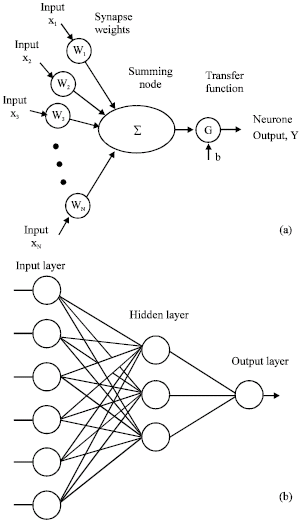
Fig. 3: | (a) Internal structure of a neuron and (b) Example of a three-layered feed forward neural network |
The fundamentals of ANNs: Neural networks are highly interconnected simple processing units designed in a way to model how the human brain performs particular task (Catalão et al., 2007; Haykin, 1999). An ANN is composed of a number of interconnected neurons which are arranged in a few layers, called input, hidden and output layers. The output of each node is a weighted sum of its inputs added to a constant term called bias (Fig. 3).
Modeling with neural networks involves two steps: These two steps are Training and testing. In training, a proper ANN is constructed via some different stages. At first, proper inputs should be selected. This stage is the most important stage which is usually done through input-output linear/nonlinear correlation analyses and probably the experiment of the ANN developer about the underlying system. The selected inputs and the output of the network are then normalized to feed them to the network. The next stage is to choose the numbers of layers and nodes of each layer as well as the transfer functions of the each neuron. This stage is normally a trial and error stages which is repeated until the best performance of network is achieved. Final stage in training includes in learning of the chosen network. A learning process in the neural network constructs an input output mapping, adjusting the weights and biases at each iteration based on the minimization of some error measure between the produced and the desired output. Thus, learning entails an optimization process. There are different learning algorithms in the literature (Almeida, 1997). One of most efficient learning algorithms is the well-known Levenberg-Marquardt algorithm. This algorithm is actually a modified Gauss-Newton method that converges 10-100 times faster than the well-known back propagation algorithm. Newton`s update for minimizing a function with respect to the vector
is given by:
![]() | (9) |
where, is the Hessian matrix and
is the gradient vector. Assuming that
is the sum of square errors, given by:
![]() | (10) |
Then:
![]() | (11) |
where, is the error vector and
is the Jacobian matrix given by:
![]() |
where, N is the number of data in training set and n is the dimension of .
is:
![]() |
Neglecting the second-order derivatives of the error vector (i.e., assuming that ) and substituting the resulting Hessian matrix into Eq. 11 and 9 we obtain the Gauss-Newton update, as:
![]() | (12) |
The advantage of Gauss Newton over the standard Newton`s method is that it does not require calculation of second-order derivatives. Nevertheless, the matrix may not be invertible. This is overcome with the Levenberg-Marquardt algorithm, which consists in finding the update given by:
![]() | (13) |
where, parameter μ is conveniently modified during the algorithm iterations. When μ is very small or null the Levenberg-Marquardt algorithm becomes Gauss-Newton, which should provide faster convergence, while for higher μ values, when the first term within square brackets of Eq. (13) is negligible with respect to the second term within square brackets, the algorithm becomes steepest descent (Catalão et al., 2007; Saini and Soni, 2002).
Evaluation indices: As stated earlier, for the evaluation of the ANN`s performance, a testing set containing new input data that it has never seen before is applied to the trained network. The performance of the trained network is then evaluated by comparison of the network output with its actual value. There are some statistical evaluation indices which are commonly used to judge about an ANN`s performance. Let Ai and Pi be the actual and network output, respectively, related to ith input vector, where N is the number of points in the testing set. Then the evaluation indices are defined as (Pao, 2007):
• | Root Mean Square Error (RMSE): |
![]() | (14) |
• | Mean Absolute Error (MAE): |
![]() | (15) |
• | Mean Absolute Percentage Error (MAPE): |
![]() | (16) |
• | Modified mean absolute percentage error (Modified_MAPE): In the relationship in Eq. 16 if the actual value is large and its prediction becomes small, the computed relative error will become near 100%. On the other hand if the actual value is small, the relative error may become very large even though the difference is small. In this case, the relationship in Eq. 16 is modified in this manner. At first, the average of actual output values is computed as: |
![]() |
and then, the Modified_MAPE will be computed as (Shahidehpour et al., 2002):
![]() | (17) |
RESULTS AND DISCUSSION
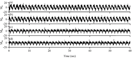
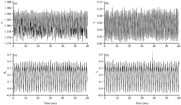
Supported by the above mentioned dynamics model of the biped robot modeling with artificial neural networks methodology, in this section, the dynamics of the robot center of mass and the robot joint angles will be modeled by neural networks. The dynamic equation of robot is considered as the system model which will be used for biped robot simulation and data generation purposes. This model has been implemented in Bipedsim for MATLB (2008) as well. The developed models are seven different neural networks which have been synthesized and evaluated via data sets of length 12000 generated by(Bipedsim). These data sets simulate walking of the underlying biped robot while surface smoothness varies as time goes on for 60 sec and sampled every 5 min. Figure 4 and 5 show the applied torques and variations of each parameter for the above mentioned period. In Fig. 4, the applied moments have been shown. Figure 5, show the resulting joint variables, i.e. y0, α, βL and γL. x0, βR and γR has not been shown here, because x0 exhibits as a straight line with constant slope (i.e., it changes with a constant speed) and βR and γR are closely similar to βR and γR, respectively.
In order for synthesizing the neural networks for modeling of each robot output variable, different input sets as well as different number of layers with different number of neurons has been considered. Due to complex nature of the robot dynamics, selection of proper inputs is a major task. In choosing input sets, one should note that the robot dynamic is a second-order one (Eq. 4). Therefore, in addition of the instantaneous values of applied input toques, some previous values of robot inputs and/or the underlying outputs should be considered as the neural networks` inputs. Considering complexity of the dynamic equations (Appendix A), up to 2 sample time previous values of each input torques and 2 sample-time previous values of the desired outputs as well as the combination of them have been proved, in this research. In this context, from different input sets the best performance of the developed networks have been achieved when the input sets consist of the applied four torques in addition to the last sample time value of the output. This fed-back output not only considers the system dynamic but also compensate for the surface non smoothness very well.
The trained networks for different variables are 5-input (4 applied moments and one fed-back output) neural networks with one hidden layer of 7 neurons and the output layer of one neuron. The transfer function of hidden layer neurons is chosen as hyperbolic tangent sigmoid transfer function, defined by:
![]() | (18) |
The transfer function used for the output layer is a pure linear transfer function. For training the network, the neural network toolbox of MATLAB (2008) was selected due to its flexibility and simplicity (Catalão et al., 2007). The network was trained by the Levenberg-Marquardt algorithm (Saini and Soni, 2002).
![]() | |
Fig. 4: | Applied input torques to the biped robot, (a) ML1 (b) MR1, (c), ML2 and (d) MR2 |
![]() | |
Fig. 5: | The robot center of mass and the robot joint angles variations in response to applied torques in Fig. 4, (a) y0, (b) α, (c) βL and (d) γL |
![]() | |
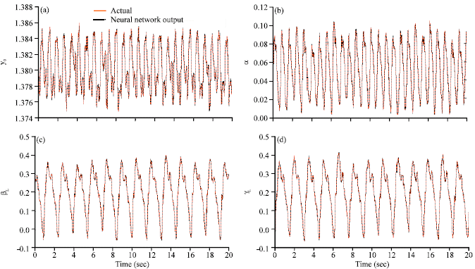
Fig. 6: | Neural networks` evaluation results for (a) y0, (b) α, (c) βL and (d) γL |
However, some other training methods were tested which amongst, the convergence rate and the prediction error for the selected method was the best. From the available data the last 40-sec data i.e. sets of 8000 data has been used for training and the remaining data have been used for the network performance evaluation.
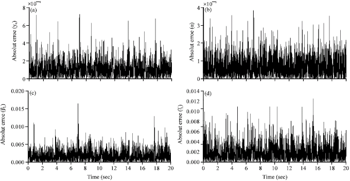
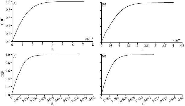
The evaluation results of synthesized neural networks have been shown in Fig. 6-8 and the evaluation indices have been brought in Table 1.
![]() | |
Fig. 7: | Absolute modeling error of the Neural networks for (a) y0, (b) α, (c) βL and (d) γL |
![]() | |
Fig. 8: | Cumulative distribution function of the absolute modeling errors shown in Fig. 5, for (a) y0, (b) α, (c) βL and (d) γL |
Table 1: | Evaluation indices for different ANN models |
![]() |
Figure 6 shows the networks` outputs in comparison with the actual data, while Fig. 7 and 8 show the absolute errors and their cumulative distribution functions, respectively.
As it is obvious from these figures, the biped robot dynamic has been very well modeled by the synthesized neural networks. Considering the simple structure of the developed networks in comparison with the robot dynamic equations, a major reduction in complexity are concluded. The evaluation results in Table 1 also emphasized the accuracy and high performance of the developed neural networks.
CONCLUSION
Employing the highly complex and nonlinear dynamics of the biped robots for their control/trajectory planning is a cumbersome task both in researches and practical implementations. On the other hand, try to solve the problems regardless of the robot dynamics may degrade the robot control performance especially where there exists disturbances such non-smooth ground surface or in case of robot dynamic mismatches. Based on these discussions, development of an easy-to-use dynamic model which considers both the nonlinear properties of the biped robot as well as the disturbance model seems very helpful. Therefore, in this study, dynamic modeling of a five-link biped robot in effect of joint torques and surface non-smoothness has been considered. Simplicity and high precision are the characteristics of the developed model, which is based on neural networks. In order for generating data for neural network training, the robot dynamics while walking on a non-smooth two-dimensional surface has been has been considered. Seven neural networks have been synthesized in order for modeling of the seven DOF of the robot. The input sets of the trained neural networks consist of four applied torques in addition to the last sample time value of each output. These fed-back outputs not only account for the system second order dynamics but also help on compensating the surface non-smoothness very well. Evaluation results are representative of high performance and much lower complexity of the trained networks with respect to the nonlinear second order robot dynamic model.
APPENDIX A
The dynamic model of the biped has the form:
![]() | (A1) |
The structure of the biped and the parameters used are shown in the Fig. 1. The vector q contains the generalized coordinates, F the ground support forces and M the joint moments. As the system has seven degrees of freedom, there exists also seven partial differential equations. In the following, the exact formulas of the inertia matrix A(q) and the right hand side vector are presented (13). A(q) is a 7x7 symmetric matrix with its upper triangular elements as:
![]() |
![]() |
and the elements of vector are:
![]() |
![]() |
REFERENCES
- Beigzadeh, B., M.N. Ahmadabadi, A. Meghdari and A. Akbarimajd, 2008. A dynamic object manipulation approach to dynamic biped locomotion. Robotics Autonomous Syst., 56: 570-582.
CrossRefDirect Link - Catalão, J.P.S., S.J.P.S. Marian, V.M.F. Mendesb and L.A.F.M. Ferreira, 2007. Short-term electricity prices forecasting in a competitive market: A neural network approach. Electrical Power Syst. Res., 77: 1297-1304.
CrossRef - Furuta, T., T. Tawara, Y. Okumura, M. Shimizu and K. Tomiyama, 2001. Design and construction of a series of compact humanoid robots and development of biped walk control strategies. Robotics Autonomous Syst., 37: 81-100.
CrossRef - Hitomi, K., T. Shibata, Y. Nakamura and S. Ishii, 2006. Reinforcement learning for quasi-passive dynamic walking of an unstable biped robot. Robotics Autonomous Syst., 54: 982-988.
CrossRef - Huang, Q., K. Yokoi, S. Kajita, K. Kaneko, H. Arai, N. Koyachi and K. Tanie, 2001. Planning walking patterns for a biped robot. IEEE Trans. Robotics Automation, 17: 280-289.
CrossRef - Hurmuzlu, Y., F. Génot and B. Brogliato, 2004. Modeling, stability and control of biped robots-a general framework. Automatica, 40: 1647-1664.
CrossRef - Kong, J.S., E.H. Lee, B.H. Lee and J.G. Kim, 2008. Study on the real-time walking control of a humanoid robot using fuzzy algorithm. Int. J. Control Automation Syst., 6: 551-558.
Direct Link - Mousavi, P.N. and A. Bagheri, 2007. Mathematical simulation of a seven link biped robot on various surfaces and ZMP considerations. Applied Math. Model., 31: 18-37.
CrossRef - Mousavi P.N., C. Nataraj, A. Bagheri and M.A. Entezari, 2008. Mathematical simulation of combined trajectory paths of a seven link biped robot. Applied Math. Model., 32: 1445-1462.
CrossRef - Pao, H.T., 2007. Forecasting electricity market pricing using artificial neural networks. Energy Conversion Manage., 48: 907-912.
CrossRef - Saini, L.M. and M.K. Soni, 2002. Artificial neural network based peak load forecasting using Levenberg-Marquardt and quasi-Newton methods. IEE Proc. Generation Transmission Distribut., 149: 578-584.
CrossRef - Zhou, C. and Q. Meng, 2003. Dynamic balance of a biped robot using fuzzy reinforcement learning agents. Fuzzy Sets Syst., 134: 169-187.
CrossRef