
M. Dursun
Department of Electrical Education, Faculty of Technical Education, Gazi University, 06500 Teknikokullar, Ankara, Turkey
Journal of Applied Sciences
Year: 2008 | Volume: 8 | Issue: 19 | Page No.: 3351-3360


ABSTRACT
In this study, destination capacity of wheelchairs has been increased by using a photovoltaic source, boost converter and employing SRM to drive wheelchair. An intelligent speed controller based on fuzzy logic was developed to increase comfort of disabled people. In addition, an accelerometer was used to measure acceleration, which is directly related to passenger comfort. All these improvements were implemented by means of a PIC18F452 microcontroller due to its low cost and superior performance.
PDF Abstract XML References Citation
How to cite this article
M. Dursun, 2008. A Wheelchair Driven with Fuzzy Logic Controlled Switched Reluctance Motor Supplied by PV Arrays. Journal of Applied Sciences, 8: 3351-3360.
DOI: 10.3923/jas.2008.3351.3360
URL: https://scialert.net/abstract/?doi=jas.2008.3351.3360
DOI: 10.3923/jas.2008.3351.3360
URL: https://scialert.net/abstract/?doi=jas.2008.3351.3360
INTRODUCTION
According to the Turkish census results of the year 2002, the total number of the people with disabilities is 1.234.139. The majority of this group is physically disabled people with the total number of 472.629 (38.2% of the total). Physically disabled or in other words, orthopedic disabled people are critically important with 38% of the total (TUIK, 2002).
The wheelchair is a fundamental vehicle for orthopedic disabled and old people to survive. With the recent technological developments, the wheelchairs, which are driven by an electrical motor, provide comfort the disabled person to move easily without a requirement of any extra force. The type of electric motor used is the basic factor which determines the comfort and distance without charging. These vehicles have the similar characteristics with electrical cars.
In the driving motors used for electric vehicles, some important features such as high instantaneous power, high power intensive, high torque at low velocities, high power at high velocities, quick response for torque demands, high efficiency at wide range of velocity and torque and low cost are desired. The switched reluctance motor has attractive potential, in view of its robustness, dynamic bandwidth and fault tolerance. An overall assessment of the approach is made based on bench performance of a prototype EMB caliper with an SR drive executing typical braking patterns. It is shown that the SR motor can provide the required overall brake actuator performance (Omekanda et al., 2006).
Switching Reluctance Motors (SRM) have high torque/size range. This motors have high torque at low speed like Direct Current (DC) serial motors (Lawrenson et al., 1980; Lawrenson and et al., 1982; Elmas and De La Parra, 1992; Miller, 1993). Therefore, these motors have required speed-torque characteristics for the electric vehicle driving system. These motors have quiet simple constructions and they are really suitable for variable speed drives due to their price, efficiency and adjustable speed, current and torque features (Miller, 1993) shows that this motor useful for industrial application. In recent years, they have been commonly used especially for variable speed drives, electric cars, elevators, centrifugal pumps and aerospace industry (Krishnan et al., 1988; Lim et al., 2008).
These motors are more suitable than asynchronous motors for solar systems since they are operated with DC. In addition, they do not need brush and commutator. However they need a good control circuit in order to get high efficiency and performance (Miller and McGilp, 1990; Bradford and Xin, 1995; Bay and Elmas, 2004; Raulin et al., 2004; Akcayol and Elmas, 2005). As a result these motors become an alternative to other motors in much application area from home applications to space studies because of the wide range of speed control abilities. Mininger et al. (2008) have controlled vibration for SRM and Mir et al. (1999) have studied about torque-ripple minimization in SRM using adaptive fuzzy control. There are different models to description and prediction of motor losses (Raulin et al., 2004). After these study focused on cost-optimized switched reluctance motor drive with bipolar currents of this motor (Grbo and Vukosavic, 2007).
In this study, to be different from other type wheelchairs, battery supported by photovoltaic source and wheelchair has been driven a SRM instead of classical DC motor. In order to control the speed of SRM, a control circuit, a drive circuit and a boost converter have been designed. The simulation and experimental results of the designed system are given.
DYNAMIC MODEL OF SWITCHING RELUCTANCE MOTOR
The electrical motor drives the wheels of the wheelchair. The power for electrical motor is obtained from the batteries. However, the wheelchair requires more power when claiming to hill or accelerating. These assistant power sources are used for short-term power supply during acceleration or uphill driving. Therefore, an auxiliary power supply is required. A second battery or a super capacitor in addition to main battery can be used as an auxiliary power supply source.
Figure 1 shows the half bridge driving circuit of a SRM with 12/8 poles. When the coil A shown in Fig. 1 is energized, the induced magnetic field pulls the nearest rotor pole towards itself. Accordingly, the reluctance is gradually minimized because of the decreasing air gap depending on the rotor position while the inductance approaches a maximum value.
SRM driver with boost converter: In order to feed SRM, many converter structures has been suggested and studied in the literature. These converters differ from each other with their way of energy recovery and strategies used commutation from one phase to another. Figure 2 shows the block diagram of SRM control circuit while Fig. 3 shows the phase winding driven by boost converter.
Dynamic model of SRM with boost converter: Figure 4 shows schematic step up chopper circuit with SRM. The dynamic performance of the system is by sets of differential equations. The first set governs the system performance when the step up chopper MOSFET is off. The off period of the boost chopper is related frequency, as follows:
Toff = (1–δ)/f | (1) |
where, δ is duty cycle of the chopper, f is switching frequency of chopper and it is equal to 1/T and the last T is switching period of chopper.
Figure 5a and b show the electric circuit diagrams of the system when the switch is at cut-off mode and at conduction mode respectively. The dynamic performance of the system has been expressed by two differential equations for the cutoff and conduction states of the boost converter switch.
 | |
| Fig. 1: | Three phased SRM with 12/8 poles and half-bridge type driving circuit |
 | |
| Fig. 2: | Block diagram of SRM control system |
 | |
| Fig. 3: | Designed converter for SRM |
 | |
| Fig. 4: | Circuit of SRM with boost converter |
 | |
| Fig. 5: | SRM circuit and the boost converter (a) switch on and (b) switch off |
For the time duration where, 0≤ t≤ Toff the following set of differential equations will describe the system performance,
(2) |
(3) |
(4) |
where, Vs is the input side voltage of the step up converter, Rc is the resistance of the chopper inductance, is is source current, Lc is the inductance of the chopper, Ra is the resistance of the motor phase, La is the inductance of the motor phase, Vc is capacitor voltage which is output side of chopper. Electromagnetic torque inducted by the motor (Te) and vehicle torque (Tv) calculate following (Bose et al., 1986)
(5) |
(6) |
where, kv is the momentum coefficient of the vehicle, ω is the radial speed of the rotor, J is inertia coefficient, B, kf is the total friction torque coefficient of motor and vehicle.
For the period when boost chopper is on, the MOSFET places short circuit across the motor and separation diode Ds is separates the solar panels and boost chopper from motor circuit at conduction state then the boost converter is at chopping state. Motor currents freewheels thorough the freewheeling diode Df. In this case the performance of the system during the period is described by the following set of differential equations (Akbaba and Akbaba, 2001).
(7) |
(8) |
(9) |
If the output voltage of the solar panel is rewritten together with the panel variables then;
(10) |
where, Rs is the inner resistance of the solar panel, Iph is the current value of the solar panel, Io is the adverse saturation current(0.0081), ∧ is the voltage coefficient of the solar panel (0.0042 V-1).
Step up converter parameters: The amplitude will be zero when the switch is ON and equal to Vo = Vc when it is OFF, because the diode MOSFET B and Ds will be conducting when the switch is OFF. The input voltage Vi will be equal to the DC component of Vs, the AC component being absorbed across the inductance Lc. Therefore:
(11) |
and
(12) |
So, the output voltage Vo is equal to capacitor voltage Vc and it is always greater than the input voltage Vi = Vs, since D is always less than unity. Lc is inductor of boost converter and VL is voltage of this inductor. It is this inductor, which receives energy from the input source when the MOSFET switch ON and then, pumps energy into the output side, during the flyback of the switch. Energy flows from the input side to the output side when the switch is turned OFF. Therefore, in boost converter shown in Fig. 4, output voltage depends on only the duty rate t1/T and input voltage Vin is independent from the load. In continuous transfer mode, the voltage of the load is also continuous. The mathematical symbols and input output parameters used in the simulation program are Vin, Vc, Io and f. By using these parameters, the value Lc is calculated by the Eq. 13:
(13) |
where VF = 0.7, diode transfer voltage. By the help of the Eq. 13 the equation of the current can be found.
(14) |
where, if ΔIL< 2IL then converter runs at continuous current mode.
(15) |
If ΔIL> 2IL then the converter runs at discontinuous mode and Eq. 14-16 are valid.
(16) |
THE FUZZY LOGIC CONTROLLER OF SWITCHING RELUCTANCE MOTOR
Figure 6 shows the block diagram of a solar wheelchair system with SRM. The system is composed of solar panel, battery, boost converter used for increasing the voltage level, 3 phases classical converters for driving SRM, SRM, position sensor, 3 items of current sensor and the PIC18F452 microcontroller (Chappell et al., 1984).
For motor feed, DC source feeds the motor power layer. For each phase of the 3 phased power layer, 2 transistors are used. Rotor position is sensed through counting the pulses obtained from the position sensor. In this circuit, the position sensor produces 1024 pulses at each cycle of the motor. The position sensors produce a reset signal after each 1024 pulses. Therefore, the exact position of the motor is detected by counting the pulses after the reset signal and the possible lines of the pulses are reset. The microcontroller produces the required signal according to the position information. During producing this signal normally, each phase begins after the end of the previous one but in order the motor momentum to be proper the phase begins before the end of the other one and they run together for a while then the other ends. The currents of the phases, which are on conduction mode, are compared with the reference signal. If the current is higher than the reference signal then, the current of that phase is cut until its value is lower than the reference signal (Bolognani and Zigliotto, 1996)
In SRM driver, 6 items of MOSFET Switches have been used and in Gate drive circuits TLP250 integrated has been used as an opto-isolator.
 | |
| Fig. 6: | Block diagram of solar wheelchair system with SRM |
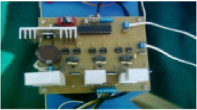 | |
| Fig. 7: | View of the completed design of the SRM driver |
A resistance of 330 Ω has been connected to the input of the integrated. Two hundred volt and 30 A IRFP 250 N have been used as MOSFET. Figure 7 shows the view of SRM driver`s completed design with the boost converter. There is one PIC microcontroller in the circuit. Pulses and reset signals are sensed by using CAP module of the microcontroller. The speed of the motor can be calculated by finding the time passed after each 24 pulses with COMPARE order. Each individual output signals are transferred to 2N25 opto-isolator. These signals are applied into the gate input of the 2113 MOSFET driver together with the signals increased up to 15 V.
In the circuit, crystal with 40 MHZ attached PIC18F452 microcontroller has been used for controlling. Sensation of two phase currents at the same time is enough for running SRM. While SRM is rotating with the rating speed of 1000 rpm the frequency of the position information is 17067 Hz. The period of this signal is 28.44 ° sec. For a stable operation the rotating speed of the controller should be shorter than this period. A 10 bit A/D conversion has been used in order to prevent missing the signals from the position sensor of the controller and accordingly instable operation of the motor.
The switching frequency is 10 kHz IRP250 type MOSFETs have been used as switching component. Resistance and plastic case roundup diode with the speed of IXYS120-60 has been used as a protection circuit. In order to minimize the fluctuation of momentum produced in SRM, a low transitive LC passive filter has been located on the output of switching component. The inductance of the filter bobbin is 5 mH and the value of the capacitor is 250 V, 470 μF. An extra diode with the same value has been added between the bobbin and the switch in order to avoid damaging the switching component by the reverse emf while cutting off due to the remnant energy.
In order to measure the phase currents LTA25N type current sensors of LEM Company have been used by setting them to 2.75 V output voltage with the current value of 2.5 A. For running SRM a incremental type position sensor attached to the motor shaft with 1024 pulses cycle-1 option. It gives a reset signal at each cycle.
The speed control of SRM is composed of a switch for changing the transfer time of the PWM signal, low transitive LC filter and classical converter for controlling SRM phase currents, SRM, position sensor, current sensors and controller.
The speed of SRM was controlled by means of fuzzy logic. The block diagram of the proposed controller was shown in Fig. 8. The error between reference speed and actual speed was assigned to be one of inputs of fuzzy logic controller while the change of error was second input to controller. The error and change error signal were scaled by 1/GE and 1/GC, respectively. Accordingly, seven linguistic variables, NB: Negative Big, NM: Negative Medium, NB: Negative Small, Zero, PB: Positive Small, PM: Positive Medium and PB :Positive Big were created for error and change of error variable (Chen and Zan, 2006). The membership functions for error and change were shown in Fig. 9a and b, respectively (De Azevedo et al., 1995; Huh and Lee, 1995; Vijayan et al., 2007).
From the block diagram, following equations could be written:
(17) |
(18) |
where, e(k) is value of error at time k, ce(k) is change of error at time (k-1), is the reference radial speed at time k, ωr (k) is actual speed at k and e(k–1) is error at time k-1. Consequently, the control signal which will be sent to SRM could be stated as follows:
(19) |
where, u(k -1) is the previous controller output value and GU is integral constants (Akpolat, 2005). The general flow chart of controller was shown in Fig. 10.
 | |
| Fig. 8: | Fuzzy logic controller system |
 | |
| Fig. 9: | Membership functions of linguistic variables |
 | |
| Fig. 10: | Flow chart of fuzzy speed controller |
SIMULATION AND EXPERIMENTAL RESULTS
The designed system is composed of PV power supply, boost converter and SRM. The parameters of SRM are 300 W, 3 phase, 12/8 poles, 2,5 A, 120 V, 1000 rpm nominal speed, β = 0.0012 coefficient of friction, J = 0.00027 momentum of inertia. The 150 W photovoltaic voltage source was regulated with a battery charger: 24 V, 15 A.
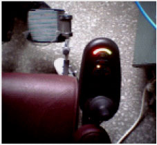 | |
| Fig. 11: | The remote controller of the disabled vehicle |
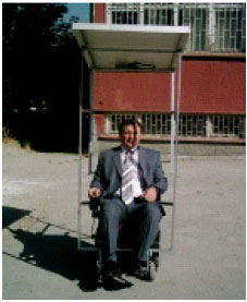 | |
| Fig.12: | The general views of the completed disabled vehicle |
The DC power supply consists of two serial connected batteries, which have 12 V capacities. The motor speed was controlled by adjusting motor voltage with boost converter. The output terminal of boost converter was connected to three phases classical converter which controls the phase currents of switched reluctance motor and friction angle.
In the simulation and the implementation, the common transfer speed and the transfer angle are set as 0-5° and 15°, respectively. The speed of SRM is controlled by speed feedback and fuzzy logic method. Figure 11 and 12 show the view of the disabled vehicle. Figure 12 shows the view of the disabled vehicle in the field which is wholly installed, operative and working with PV.
The differential expressions in the dynamic equations are presented by 4° Runga Kutta Method and by using the programming language of C. The obtained data is represented graphically.
 | |
| Fig. 13: | A phase current in simulation |
 | |
| Fig. 14: | A phase current on oscilloscope |
 | |
| Fig. 15: | Motor phase currents at the departure moment of the vehicle |
The switching angle of the phase currents is arranged on a basis that no negative torque will be produced. The Torque fluctuation can be prevented by different control techniques for the charges in which sensitive and stable torque is needed. In these methods, the torque is a little bit reduced.
Figure from 13-17 show the vehicle on a straight and smooth road; from Fig. 18-21 show the changes it is moving with an angle of 10°. Figure 22-25 shows its movement on a bumby road. Where, 0,1 Nm load torque between 0-0.1 sec, 0.3 Nm load torque between 0.1-0.2 sec; 0.2 Nm load torque between 0.2-0.3 sec, 0.5 Nm load torque between 0.3-0.35 sec; 0.2 Nm load torque between 0.35-0.5 sec.
 | |
| Fig. 16: | Motor phase currents after the first ovement of the vehicle |
 | |
| Fig. 17: | Acceleration curves of the vehicle on smooth floor |
 | |
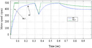
| Fig. 18: | The fluctuation at motor speed during stable operation |
 | |
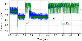
| Fig. 19: | The fluctuation at motor torque during stable operation |
 | |
| Fig. 20: | Phase A current at the departure moment of the vehicle on a 10° slope |
 | |
| Fig. 21: | Motor phase currents after the first movement of the vehicle on a 10° slope |
 | |
| Fig. 22: | Acceleration curves of the vehicle on a 10° slope |
 | |
| Fig. 23: | The fluctuation at motor torque during stable operation on a 10° slope |
And finally 0.4 Nm load torque between 0.6-0.7 sec has been applied. Figure 25 shows motor phase currents after the first movement of the vehicle on a bumpy road and it resembles to Fig. 24.
Figure 14 shows the view of a phase current on a digital oscilloscope. The saved current views in the simulation and the implementation is seemed to be very similar. From here, we can say that the motor dynamic equations and the modelling are almost real.
Figure 26 shows Speed up curves versus to time of the vehicle on a bumpy road after the first movement of the vehicle on a bumpy road. Figure 27 shows that the fluctuation at motor torque during stable operation on a bumpy road. It can be seen that Fig. 25 and 26 while the vehicle running on bumpy rood motor torque is good adaptive to rood indirectly speed is constant.
 | |
| Fig. 24: | Motor phase currents at the start up moment of the vehicle on a bumpy road |
 | |
| Fig. 25: | Motor phase currents after the first movement of the vehicle on a bumpy road |
 | |
| Fig. 26: | Speed up curves versus to time of the vehicle on a bumpy road |
Acceleration of a disabled vehicle: In this study, ICP Accelerometer belonging to Piezotronics Company; DAQ 6036 E Card belonging to National Instrument Company and BNC2110 Connector and also the 8.2 version of Laboratory Virtual Instrumentation Engineering Workbench (LabVIEW) graph program have been used. Figure 28 shows the acceleration of the vehicle at the speed-up moment. It can be seen from Fig. 28 that 0.6th sec vehicle started to speeding up and acceleration is about 0.012 m sec-2. After the 1.6th second the speed changing of vehicle is slower than by than acceleration is decreases to zero.
Figure 29 shows motor speed versus to current, Fig. 30 shows speed-voltage relation and Fig. 31 shows the power consumed curves versus to the speed at no load.
 | |
| Fig. 27: | The fluctuation at motor torque during stable operation on a bumpy road |
 | |
| Fig. 28: | Acceleration of the vehicle at the speed-up moment |
 | |
| Fig. 29: | Line current changes versus to the speed |
 | |
| Fig. 30: | Voltage change curve versus to the speed |
 | |
| Fig. 31: | Power consumed curve according to the start-up |
CONCLUSION AND EVALUATION
Destination capacity and overall performance of wheelchairs for disabled people has been increased by using a photovoltaic source and employing SRM to drive wheelchair. Accordingly, disabled people will able to use their wheelchair for long distance without worrying about system batteries. In addition, their traveling comfort was increased by means of proposed intelligent speed controller and accelerometer used. It has been shown that all these improvements could be done by using an low cost PIC18F452 microcontroller. The main drawback of the overall system is that its performance depends on sun light, which is uncontrollable variable. As a result, the performance of medical equipment used for disabled people has been improved.
ACKNOWLEDGMENTS
Many thanks to managers and employees of Gazi University Scientific Research Project Unit and BELMO Cooperation in Turkey for all their contribution and support for this study with the Project code of 2006/20.
REFERENCES
- Akbaba, M. and M.C. Akbaba, 2001. Dynamic performance of a photovoltaic-boost converter powered DC motor-pump system. Proceedings of the International Electric Machines and Drives Conference, June 17-20, 2001, Cambridge Massachusetts, USA., pp: 356-361.
Direct Link - Akcayol, M.A. and C. Elmas, 2005. NEFCLASS-based neuro fuzzy controller for SRM drive. Eng. Appl. Artificial Intel., 18: 595-602.
CrossRef - Akpolat, Z.H., 2005. Non-singleton fuzzy logic control of a DC motor. J. Applied Sci., 5: 887-891.
CrossRefDirect Link - Bay, O.F. and C. Elmas, 2004. Modeling of the inductance variation and control of the switched reluctance motor based on fuzzy logic. Intel. Automation Soft Comput., 10: 233-246.
Direct Link - Bolognani, S. and M. Zigliotto, 1996. Fuzzy logic control of a Switched reluctance motor drive. IEEE Trans. Ind. Appl., 35: 1063-1068.
CrossRefDirect Link - Bose, B.K., J.E.M. Timothy, P.M. Szczesny and W.H. Bicknell, 1986. Microcomputer control of switched reluctance motor drive. Industry applications. IEEE Trans., IA-22: 708-715.
CrossRefDirect Link - Bradford, J.N. and F. Xin, 1995. A new approach to the nonlinear fuzzy control of the switched reluctance motor. Proceedings of the International Conference on Systems, Man and Cybernetics. Intelligent Systems for the 21st Century at Vancouver, October 22-25, 1995, British, Columbia, pp: 171-176.
CrossRef - Chappell, P.H., W.F. Ray and R.J. Blake, 1984. Microprocessor control of a variable reluctance motor. IEEE Proc. B, Elect. Power Appl., 131: 51-60.
Direct Link - De Azevedo, H.R., T.T. Borges, N. Salvador and E.P. Teixeira, 1995. Reluctance motor drive based on fuzzy logic. Intel. Inform. Syst. ANZIIS-95, 1: 226-231.
CrossRefDirect LinkINSPEC - Elmas, C. and H.Z. Parra De La, 1992. A DSP controlled switched reluctance drive system for wide range of operating speeds. Proceedings of the 23rd Power Electronics Specialists Conference, Jun 29-Jul 3, 1992, Toledo, Spain, pp: 844-850.
CrossRefDirect Link - Grbo, Z. and S. Vukosavic, 2007. Cost-optimized switched reluctance motor drive with bipolar currents. Elect. Eng., 89: 183-191.
CrossRefDirect Link - Huh, U.Y. and T.G. Lee, 1995. Fuzzy logic based switching angle controller for SR motor speed control. Proceedings of the International Symposium on Industrial Electronics, July 10-14, 1995, Athens, Greece, pp: 809-814.
CrossRefDirect Link - Krishnan, R., R. Arumugan and J.F. Lindsay, 1988. Design procedure for switched reluctance motors. IEEE Trans. Ind. Appl., 24: 456-461.
Direct Link - Lawrenson, P.J., J.M. Stephenson and P.T. Blenkinsop, 1980. Variable-speed switched reluctance motors. IEE Proc. B, Electr. Power Appl., 127: 253-265.
Direct Link - Lim, H.S., R. Krishnan and N.S. Lobo, 2008. Design and control of a linear propulsion system for an elevator using linear switched reluctance motor drives. IEEE Trans. Ind. Elect., 55: 534-542.
CrossRefDirect Link - Miller, T.J.E. and M. McGilp, 1990. Non-linear theory of the switched reluctance motor for rapid computer aided design. IEE Proc. B, Elec. Power Applied, 137: 334-347.
Direct LinkINSPEC - Mininger, X., E. Lefeuvre, M. Gabsi, C. Richard and D. Guyomar, 2008. Semiactive and active piezoelectric vibration controls for switched reluctance machine. IEEE Trans. Energy Convers., 23: 78-85.
CrossRefDirect Link - Mir, S., M.E. Elbuluk and I. Husain, 1999. Torque-ripple minimization in switched reluctance motors using adaptive fuzzy control. IEEE Trans. Ind. Appl., 35: 461-468.
Direct Link - Omekanda, A.M., B. Lequesne, H. Klode and S. Gopalakrishnan 2006. Switched reluctance and permanent magnet brushless motors in highly dynamic situations: A comparison in the context of electric brakes. Proceedings of the 41st Annual Meeting Conference on Industry Applications, October 18-22, 2006, IEEE, pp: 1570-1577.
Direct Link - Raulin, V., A. Radun and I. Husain, 2004. Modeling of losses in switched reluctance machines. IEEE Trans. Ind. Appl., 40: 1560-1569.
CrossRefDirect Link - Vijayan, S. et al., 2007. A practical approach to the design and implementation of speed controller for switched reluctance motor drive using fuzzy logic controller. J. Elect. Eng. Elektrotechnicky Casopis, 58: 39-46.
Direct Link
Bandara Sumanarathna Reply
Good explanation of the structure. Would be complete with codes and circuites.
Mahir Dursun
Plaese you send me what do want? If you explain what will you do, I can send some.
Sincerelly
Dr. Mahir Dursun