
Habtamu Beri
Department of Manufacturing and Automation, Harbin Institute of Technology, Harbin, 150001, China
Yingxue Yao
Department of Manufacturing and Automation, Harbin Institute of Technology, Harbin, 150001, China
Journal of Environmental Science and Technology
Year: 2011 | Volume: 4 | Issue: 3 | Page No.: 302-312


ABSTRACT
Darrieus type Vertical Axis Wind Turbine (VAWT) is attracting many researches for its inherent advantages and its diversified applications. However, a disadvantage is when the rotor is stationary; no net rotational force arises, even at high wind speed. The objective of this study is to show the effect of camper airfoil on self starting of VAWT at low Reynolds. A moving mesh technique was used to investigate two-dimensional unsteady flow around a vertical axis wind turbine. The geometry of the turbine blade was NACA2415 camber airfoil. The turbine model was created in Gambit modeling software and then read into fluent software for fluid flow analysis. Simulations of the model were then conducted for different tip speed ratios. The simulation result shows that camber airfoils have the potential to self start for the modeled airfoil with reduced coefficient of power.
PDF Abstract XML References Citation
Received: August 04, 2010;
Accepted: September 15, 2010;
Published: November 12, 2010
How to cite this article
Habtamu Beri and Yingxue Yao, 2011. Effect of Camber Airfoil on Self Starting of Vertical Axis Wind Turbine. Journal of Environmental Science and Technology, 4: 302-312.
DOI: 10.3923/jest.2011.302.312
URL: https://scialert.net/abstract/?doi=jest.2011.302.312
DOI: 10.3923/jest.2011.302.312
URL: https://scialert.net/abstract/?doi=jest.2011.302.312
INTRODUCTION
At present, there are two categories of modern wind turbines, namely Horizontal Axis Wind Turbines (HAWTs) and Vertical Axis Wind Turbines (VAWTs), which are used mainly for electricity generation (Izli et al., 2007). Though VAWTs have inherent advantages, HAWTs are dominant commercially. The principal advantages of the vertical axis format are their ability to accept wind from any direction without yawing and the ability to provide direct rotary drive to a fixed load. The absence of yaw requirement simplifies the design of the turbine. Blades of VAWT may be of uniform section and untwisted, making them relatively easy to fabricate or extrude, unlike the blades of HAWT, which should be twisted and tapered for optimum performance. Furthermore, almost all of the components requiring maintenance are located at the ground level facilitating the maintenance work appreciably. However, its high torque fluctuations with each revolution, no self-starting capability are the drawbacks (Islam et al., 2008; The Worlds of David Darling, 2009).
VAWTs received little attention and largely forgotten until the oil crises of the early 1970s. The oil crises stimulated a revival of interest in a range of renewable energy conversion devices including drag and lift type (Savonius and Darrieus) of VAWT. Then interest in VAWT has declined since the late 1980s as the propeller shaped HAWT has become established as the standard form of wind turbine (Shikha Bhatti and Kothari, 2009). Recently darrieus type VAWT is attracting many researchers for its inherent advantages and diversified applications. A comparative study made by Sandra et al. (2008) shows that VAWTs are advantageous to HAWTs in several aspects.
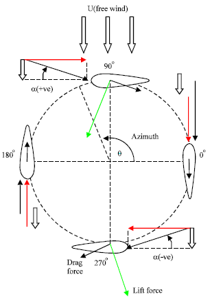 | |
| Fig. 1: | Top view of forces on a darrieus blade throughout 360° of rotation (winturbine-anlysis.com). Double arrow represents-air velocity relative to the ground; Red arrow-velocity of the ground relative to the airfoil; Black arrow-resultant air velocity relative to the airfoil |
Other many research works showed that VAWT has the potential to compete with the more widely used conventional HAWTs if the inability of the turbine to self start is resolved.
Early attempts at improving the self starting of VAWT was concentrated on optimizing configurations of static geometric parameters which includes turbine solidity, blade camber and thickness, blade offset pitch angle and blade lean forward (or yaw) angle (Lazauskas, 1992). Other approaches that were proposed to improve self starting includes the use of cambered blade sections (Dereng, 1981), use of inclined blades (Barker, 1983), use of flexible sails (Hurley, 1979), savonius darrieus hybrid (Wakui et al., 2005), variable pitch (Drees, 1979; Liljegren, 1984). Though, the approaches were tend to contribute in the increases of starting torque, reductions in peak efficiencies and working on the operating range were some of the major problems.
The forces driving darrieus turbines can be described in more detail with the help of Fig. 1. There are two important velocity components. There is the velocity of the airfoil relative to the shaft, which is at all times parallel to the chord, having a magnitude equal to the rotational speed multiplied by the radius. There is also the velocity of the wind, which is approximated as a constant velocity in one direction. The resultant of these two velocities is the velocity of the air relative to the airfoil. The angle between this resultant velocity and the chord of the airfoil is called the angle of attack (α).
Lift is created by a pressure differential, which occurs whenever there is an angle of attack, α, not equal to zero. In the 0° azimuth position and the 180° position, α = 0°. At this point, only a drag force exists. Lift begins to be created as the blades rotate out of these two positions and α increase.
This lift force is perpendicular to the resultant wind direction but, more importantly, it always induces counterclockwise rotation of the turbine. This lift force is the force that is used to power the wind turbine.
The computational research on the cambered airfoil is difficult to find in the literature. Therefore, the ultimate goal of this study is the development of analysis method of the VAWT with cambered airfoil. The present study is the first report of the study to show self staring capability of cambered airfoil using CFD computational analysis. First, the flow NACA2415 was simulated and analyzed for different angles of attack. The results were then validated against the experimental data to verify the performance of the code. Then the computational analysis of two-dimensional (2D) unsteady flow around the turbine was performed. The commercial CFD software, Fluent 6.3.26 version was used for the analysis. Different Tip-Speed Rations (TSR) of the turbine were studied to indicate the self starting torque of the turbine and its performance.
Computational Fluid Dynamics (CFD) codes solving the Reynolds-Averaged Navier-Strokes (RANS) equations are applied in many different ways. In this study, the computations of the flow around a rotational VAWT, based on the solution of the RANS equations, are performed with a moving mesh technique for the simulation of the wind turbine movement. The Darrieus type VAWT having a lift-based torque with three cambered fixed pitch blades was used. The blades are based on a NACA 2415 cambered airfoil section, with chord length C = 1 m and the rotor radius is R = 4 m without shaft at the center as it has significant effect on the performance of the turbine.
MATERIALS AND METHODS
Two-dimensional unsteady analysis of a vertical axis wind turbine model of NACA2415 camber airfoil was analyzed using a Computational Fluid Dynamic, CFD tool solving the reynolds-averaged navier-stroke equations based on moving mesh technique. Simulations were conducted on July 10 and 11, 2010, using high processing capacity of 8 GB computer. The laboratory is located in the Zoo Campus of Harbin Institute of Technology, Department of Manufacturing and Automation. The overall procedures followed in the analysis are described as follows:
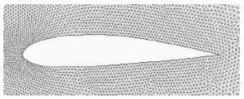
Computational domain: Cambered airfoil type NACA2415 (Fig. 2) was selected as blade section. The airfoil was set to 1 m chord length and the turbine radius was set to 4 m to minimize the interference between the blades. For creating 2D model and mesh of the model, Gambit 2.3.16 version modeling software was used.
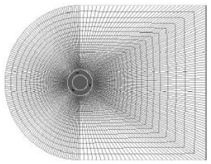
The domain size was set as shown in Fig. 3 with a rotating sub-domain surrounding the blades and stationary sub domains in the remaining region. Mesh for the rotating sub-domain and central sub-domains were generated with triangular blocks where as the rest sub-domains were generated with O-H structured grid. The rotating sub-domain was set to a diameter of 10 m. The inlet width and out let width were set to 3D. The inlet was located 3D upstream and outlet 6D downstream.
Computational method: The model and mesh generated in gambit modeling soft ware were read into the commercial CFD code, fluent V.6.2.30 for numerical iterative solution. The RANS equations were solved using the green-gauss node based gradient option and the sliding mesh method was used to rotate the sub-domain for the turbine blades. For pressure-velocity coupling, the simple algorithm was used. Standard was set as pressure discretization and first order upwind was set for momentum. Time integration was done implicitly and the minimum convergence criteria were set to 1e-06. The RNG k-epsilon model was adapted for the turbulence closure.
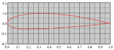 | |
| Fig. 2: | NACA2415 blade section |
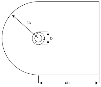 | |
| Fig. 3: | Computational domain |
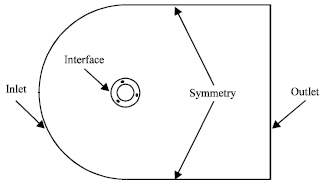 | |
| Fig. 4: | Boundary conditions |
The boundary conditions are shown in Fig. 4. The inlet was defined as a velocity inlet, which has constant inflow velocity while the outlet was set as a pressure out let, keeping the pressure constant. The velocity at the out let was determined by the extrapolation from inside. The no slip shear condition was applied on the turbine blades, which sets the relative velocity of blades to zero. There were four domains in the computational domain with 72,908 cells of the meshes with 180 cells around each blade. The cells were concentrated near the blades for better result. The Reynolds number based on rotor diameter was 2.2 million and the blade chord reynolds number was 270,000.
For the moving mesh simulations, the computational sub-domain is split into a moving part around the turbine and a fixed part for the fixed environment. The rotational motion is simulated by allowing the mesh block around the wind turbine to rotate at constant angular velocity.
 | |
| Fig. 5: | Overall view of the mesh |
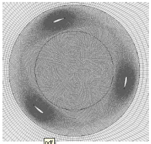 | |
| Fig. 6: | Rotating sub-domain |
 | |
| Fig. 7: | Mesh near the airfoil |
The mesh movement is defined explicitly by specifying time-varying positions for all of the moving mesh block cell vertices. An interface boundary surrounding the moving mesh part within the model slides at the specified velocity. This represents the relative motion between the rotating wind turbine and the fixed environment.
Figure 5 shows the overall view of the 3-bladed turbine model mesh and Fig. 6 shows the zoom-in view around the rotating sub-domains. As can be seen from Fig. 5 and 6, the cells were concentrated near the blades for better result. Figure 7 shows the cells around the blades.
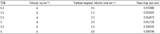
The flow condition used for the analysis is shown in Table 1. Time step size was set corresponding to 2 degree for each rotational speed of the rotor (ω) given in Table 1 corresponding to each TSR. Eighty iterations were used per time step.
The operating speed of the turbine, expressed as Tip Speed Ration (TSR) was set between 0.5 and 4.
TSR is defined as:
| (1) |
where, R is the turbine radius, ω is angular velocity and V∞ is the free stream velocity.
RESULTS
Figure 8 shows simulated average torque values at lower TSR which was the main focus area of the study. It shows the average torque in N-m for complete revolution of the modeled turbine for TSRs 0.5 and 1.5. The torque values were obtained from coefficient moment (Cm) of the modeled turbine, air density, area of turbine, free stream velocity chosen and the radius of the turbine modeled.
Figure 9 shows simulated average torque values at higher TSR. This shows the average torque in N-m for complete revolution of the modeled turbine for TSRs 2.5, 3, 3.5 and 4. The torque values were obtained using the same principle as mentioned above. This graph is used to determine the efficiency of the modeled turbine.
Figure 10 shows the coefficient of power (Cp) for the simulated model, which determines the performance of the turbines. It shows Cp at the given value of TSR selected for the simulation. The maximum efficiency of the modeled airfoil was appeared around TSR of 2.5. The coefficients of power were obtained from the ration of the modeled turbine power to the available wind power in the air.
| Table 1: | Flow condition |
 | |
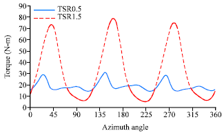 | |
| Fig. 8: | Torque for TSR 0.5 and 1.5 |
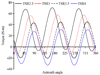 | |
| Fig. 9: | Torque for higher TSR |
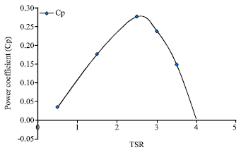 | |
| Fig. 10: | Power coefficients vs. TSR |
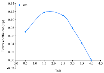 | |
| Fig. 11: | Coefficient of moment vs. TSR |
Figure 11 shows the coefficient of moment (Cm) of the simulated model, which determines the average torque of wind turbines. It shows the value of the coefficient of moment of airfoils for the given TSR. The Cm values were obtained from the average moment of the three airfoils modeled through CFD computational analysis.
DISCUSSION
To verify the reliability of the computational method, hydrodynamic forces acting on the NACA2415 airfoil from different angles of attack were computed. The cord length was set to 1m and the corresponding cord-based Reynolds number Re, was 85,000. The converged solution was obtained after 4,000 iterations. Figure 12 shows the comparison of the computational solutions and experimental data (Kirke, 1998). The computed lift forces are in good agreement with the data for angles of attack between -10 and 10° which is considered to be the normal operating range of turbine blades.
Torque: The blade aerodynamic forces and torque are computed from the solution of RANS equations through the integration of the pressure and shear stress over the blade surface. The total wind turbine force components and torque are obtained by adding the 3 blade force components and torque. The driving torque is obtained by calculating the average of the instantaneous values corresponding to the last revolution of the rotor. These values were used to derive the expected wind turbine power coefficient (Cp). The turbine was allowed to turn until stable torque was created and the minimum no of turns used for this model was 6.
| (2) |
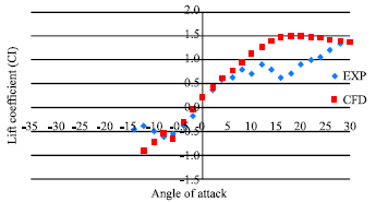 | |
| Fig. 12: | Lift coefficient of NACA2415 |
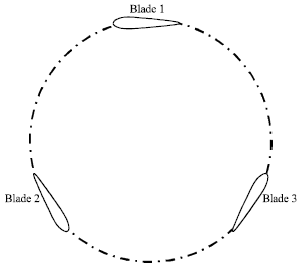 | |
| Fig. 13: | Blade position at time = 0.00e+00, ΔΦ = 0° |
where, p is expected out put power of turbine, ω is angular velocity of turbine, T averaged torque
Cp is then calculated as:
| (3) |
where, ρ is the air density, V8 free stream velocity, A frontal area of the turbine.
Traditionally airfoils that are used for VAWTs are symmetrical airfoils NACA0012, NACA0015 and NACA0018. The main drawbacks with these types of section are their minimum or negative torque generation for the lower TSR. As can be seen from the result, all the torque values are positive for lower TSR for the modeled NACA2415 which implies camber airfoils have great potential in self staring of VAWTs. However, the coefficient power (Cp) result shows a reduced efficiency as compared to the conventional symmetrical airfoils of NCACA 0012, NACA0015 and NACA0018 which are not self starting. This is in agreement with Lazauskas (1992), Barker (1983), Kirke and Lazauskas (1991), Healy (1978) and Kotb (1990) that a judicious choice of camber airfoil can increase starting torque but reductions in peak efficiency and narrower operating ranges are the drawbacks.
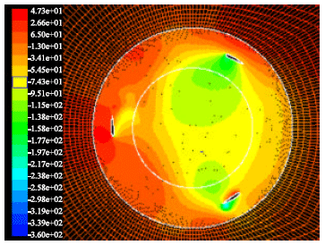 | |
| Fig. 14: | Pressure contours for TSR = 3 at time = 5.2776e-01, ΔΦ = 90° |
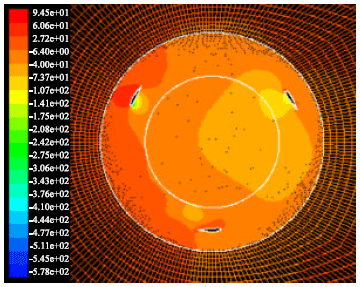 | |
| Fig. 15: | Pressure contours for TSR = 3 at time = 1.005552e+00, ΔΦ = 180° |
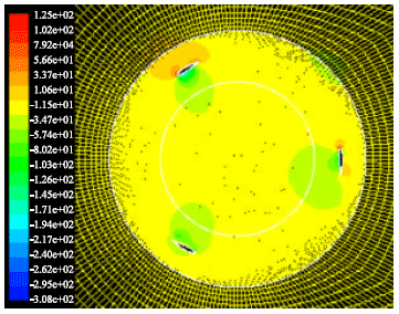
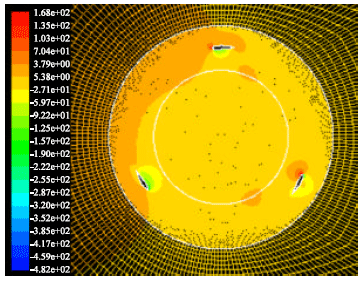
The pressure contours at four different positions change of azimuth angle (ΔΦ) for one complete turn of the turbine are shown with the help of figures. The snap shot pressure contour distributions were taken for TSR 3 and the turbine was modeled to turn anticlockwise.
Figure 13 shows blade position at stationary stage of the turbine. At this point time is zero and change of azimuth angle (ΔΦ = 0). Figure 14 shows a snap shot of pressure distribution after the turbine has rotated 90°. The time at this position is 0.52776 s and the change of azimuth angle is 90°. Figure 15 shows a snap shot of pressure distribution after the turbine has rotated 180°. At this position the time is 1.05552 s and the change of azimuth angle is 180°. Figure 16 shows a snap shot of pressure distribution at time 1.58328 s and change of azimuth angle of 270°. Figure 17 shows a snap shot of pressure distribution after the turbine has turned one complete revolution. The time at this position is 2.11104 s and the change of azimuth angle is 360°.
 | |
| Fig. 16: | Pressure contours for TSR = 3 at time = 1.58328e+00, ΔΦ = 270° |
 | |
| Fig. 17: | Pressure contours for TSR = 3 at time = 2.11104e+00, ΔΦ = 360° |
CONCLUSIONS
Firstly the hydrodynamic forces acting on NACA2415 cambered airfoil section were computed from different angles of attack to validate the computational method to experimental data. Then 2D unsteady flow analysis using the selected airfoil section with fixed pitch three blades based on RANS equation have been analyzed with a moving mesh technique. The simulated average torque result shows that camber airfoils have the potential to self start if used for vertical wind axis wind turbines. However, the power coefficient of the simulated model shows a reduction in peak efficiencies compared to the conventional non-self starting airfoils.
REFERENCES
- Izli, N., A. Vardar and F. Kurtulmu, 2007. A study on aerodynamic properties of some NACA profiles used on wind turbine blades. J. Applied Sci., 7: 426-433.
CrossRefDirect Link - Islam, M., D.S.K. Ting and A. Fartaj, 2008. Aerodynamic models for darrieus-type straight-bladed vertical axis wind turbines. Renewable Sustainable Energy Rev., 12: 1087-1109.
CrossRef - Eriksson, S., H. Bernhoff and M. Leijon, 2008. Evaluation of different turbine concepts for wind power. Renewable Sustainable Energy Rev., 12: 1419-1434.
CrossRefDirect Link - Shikha Bhatti, T.S. and D.P. Kothari, 2009. Early development of modern vertical and horizontal axis wind turbines: A review. Wind Eng., 29: 287-300.
CrossRefDirect Link - Lazauskas, L., 1992. Three pitch control systems for vertical Axis wind turbines compared. Wind Eng., 16: 269-269.
Direct Link - Barker, J.R., 1983. Features to aid or enable self starting of fixed pitch low solidity vertical axis wind turbines. J. Wind Eng. Ind. Aerodynamics, 15: 369-380.
CrossRef - Wakui, T., Y. Tanzawa, T. Hashizume and T. Nagao, 2005. Hybrid configuration of Darrieus and Savonius rotors for stand-alone wind turbine-generator systems. Electrical Eng. Jap., 150: 13-22.
Direct Link - Healy, J.V., 1978. The influence of blade camber on the output of vertical axis wind turbines. Wind Eng., 3: 146-155.
Direct Link
naseem salim alomoush Reply
i need best airfoil profile for vawt (H-darrieus) to get 100W ,at 5m/s design speed.
Habtamu B.T
The main draw backs with VAWT is self starting at low reynold numbers. the most commonly used airfoil profiles are NACA0012,NACA0015, and NACA0018. however, these profiles have self starting problems. airfoils with self staring airfoils like camber airfoil have efficency problems. therefore, there is no best airfoil profile I recommend.