
A. Shahzad
Malaysian Institute of Information Technology (MIIT), 1016,Jalan Sultan Ismail, Universiti Kuala Lumpur, 50250, Kuala Lumpur, Malaysia
S. Musa
Malaysian Institute of Information Technology (MIIT), 1016,Jalan Sultan Ismail, Universiti Kuala Lumpur, 50250, Kuala Lumpur, Malaysia
M. Irfan
Windfield College, Paser Seni, Kuala Lumpur, Malaysia
S. Asadullah
Kulliyah of Information and Communication Technology, International Islamic University, Malaysia
Journal of Applied Sciences
Year: 2014 | Volume: 14 | Issue: 20 | Page No.: 2487-2497


ABSTRACT
The current study is based on novel solution which deploy the security mechanism, more advance cryptography solution within Distributed Network Protocol (DNP3) stack as a part of critical system (or SCADA system). The “Dynamic Cryptography Buffer (DCB)” has been implemented that contains 56 bytes from total size of “Application Protocol Data Unit (APDU) bytes” as a part of application layer of DNP3 protocol. The DCB contains several fields/subfields which have been used during implementation of cryptography algorithms and other information (or detail) related with protocol security. During implementation within DNP3 protocol, the bytes are dynamically stored after processing (security deployment) within DCB, without affecting the total size of DNP3 protocol stack. This novel study gives new directions for SCADA or its protocols security deployment and enhancement.
PDF Abstract XML References Citation
Received: February 03, 2014;
Accepted: June 07, 2014;
Published: June 28, 2014
How to cite this article
A. Shahzad, S. Musa, M. Irfan and S. Asadullah, 2014. Deployment of New Dynamic Cryptography Buffer for SCADA Security Enhancement. Journal of Applied Sciences, 14: 2487-2497.
DOI: 10.3923/jas.2014.2487.2497
URL: https://scialert.net/abstract/?doi=jas.2014.2487.2497
DOI: 10.3923/jas.2014.2487.2497
URL: https://scialert.net/abstract/?doi=jas.2014.2487.2497
INTRODUCTION
The SCADA system has been used several protocols “such as profibus protocol, modbus protocol, DNP3 protocol, foundation fieldbus protocol, IEC 60870-5 protocol and other series, modbus plus protocol and data highway plus/DH-485 protocol”, for the purpose of industrial automation and processing. Each protocol has distinct specifications during installation, configuration and transmission services. The Distributed Network Protocol (DNP3) is most important and famous protocol that has been used in industrial processing (or SCADA processing) (Shahzad and Musa, 2012; Shahzad et al., 2013).
The DNP3 protocol has contains four layers included “application layer, pseudo-transport layer, data link layer and physical layer”, in its stack and used “Transport Control Protocol/Internet Protocol (TCP/IP)” over internet. The application layer of DNP3 protocol takes random bytes from upper layer (user application layer) and able to process 2048 bytes to lower layer. The each size of Transport Protocol Data Unit (TPDU) is up to 250 bytes with header byte while data link layer is able to receive 250 bytes from pseudo-transport layer and transmit 292 bytes with 32 Cyclic Redundancy Checker (CRC) bytes to physical layer included 10 bytes of header (Musa et al., 2013a, b; Shahzad et al., 2014a).
NEW DNP3 PROTOCOL SECURITY STACK
The new DNP3 protocol security stack has number of fields/subfields which are utilized during cryptography implementation (proposed implementation). The detail related with fields/subfields is as followed.
Source address and port: This is 2 bytes (unassigned) field within stack which identifies the source address and port, either master station send request or remote station send response.
Destination address and port: This is also 2 bytes (unassigned) field within stack which identifies the destination address and port, either master station received response message or remote station received request message.
User bytes: This field defines the bytes (user bytes) that are being used by security (proposed solution) implementation within each layer.
| • | User bytes: Application Protocol Data Unit (APDU) size is up to 1992 bytes and Application Protocol Control Information (APCI) is 2 or 4 bytes within APDU, case of request or response |
| • | User bytes: Transport Protocol Data Unit (TPDU) size is up to 250 bytes and Transport Protocol Control Information (TPCI) has 1 bytes within TPDU, both request and response message (bytes) |
| • | User bytes: Link Protocol Data Unit (LPDU) size is up to 292 bytes (with optional CRC bytes) and Link Protocol Control Information (LPCI) has 10 bytes within LPDU, both for request and response |
Cryptography key sequence: This is 4 bytes (unassigned) subfield within stack (cryptography implementation field) and used to keep the track of cryptography keys during message (bytes) generation within each layer of DNP3 protocol. Each time security is implemented in layers include application layer, pseudo-transport layer and data link layer (Musa et al., 2013a; Shahzad et al., 2014b), cryptography counter is updated and value is added in cryptography key sequence field. The two flags are used within each layer to monitor the status of security (cryptography implementation). More detail is depicted in Table 1.
This field also keeps the record of message (bytes) during communication. Each time message (bytes) is transmitted to remote station, counter is incremented by one and value is update in cryptography key sequence field.
Dynamic storage (bytes): This is dynamic byte subfield within stack (cryptography implementation field) and used to store cryptography implementation information. In start, this subfield occupy 16-56 bytes within stack, either message (bytes) request or response. In case, dynamic buffer is full and acquired additional space for cryptography implementation than CRC (32 bytes) from data link layer are used for additional bytes storage.
Optional (bytes): This is 2 bytes (unassigned) subfield within stack (cryptography implementation field) and usually implemented at the end of DNP3 stack or when message is ready to transmit (request or response). This subfield is used to verify all contents during message (bytes) generation process.
Padding bytes: This subfield occupies dynamic bytes within stack (cryptography implementation field). In case, dynamic buffer has extra memory space than this space is filled with padding bytes. This function indicates that message (byte) has been constructed and ready for transmit (send or response) to desire station.
| Table 1: | Cryptography key sequence status |
 | |
Acknowledgment: This is 2 bytes (unassigned) subfield within stack (cryptography implementation field). During communication, master station send request message (bytes) with acknowledgment flag (set) than upon receiving, remote station also send acknowledge message to mater station, not data.
| • | ACK, flag (0): Indicate master/remote station communication without acknowledgment |
| • | ACK, flag (1): Indicate master/remote station communication with acknowledgment |
Critical (bytes): This is optional 1 bytes (unassigned) subfield within stack (cryptography implementation field). In case, attacks are successfully within communication, this field shows the status or system behavior.
Non- critical (bytes): This is optional 1bytes (unassigned) subfield within stack (cryptography implementation field). In case, attacker attack but not successfully within communication, this field shows the status or system behavior.
Solution (select method): This is one bytes (unassigned) subfield within stack (cryptography implementation field) and used to identified which cryptography method is currently using for SCADA/DNP3 security (depend on requirement). Figure 1 illustrates the new DNP3 protocol security stack while Table 2 shows the detail fields/subfields description of new DNP3 protocol security stack.
RESULTS AND DISCUSSION
Dynamic buffer utilization and command request (bytes): The below APDU bytes (MTU request), logical 98 bytes (request dummy bytes) have been transmitted from MTU (sender) application layer to RTU (receiver) application layer. The below bytes (MTU application layer) are the request message being transmitted from MTU to RTU while the heighted bytes show the Application layer Header or AH information, object header information and security information. The other heighted byte, 0x00c3 is application control information and 0x0001 is the function code (uses for read request).
 | |
| Fig. 1: | New DNP3 protocol security stack |
| Table 2: | Fields/subfields description: New DNP3 protocol security stack |
 | |
Request APDU bytes (logical) are presented as follows:
 |
The bytes, 0x00ie and 0x0002 are designated for group and variation fields. The byte, 0x0000 is qualifier field which is used both in request/response message while data object are acquired (needed) from contiguous indexes. The bytes, 0x0004-0x0007 are designated for range fields. The remaining bytes 0x001e, 0x000ee, 0x001a, 0x00ee, 0x0002a and 0x00ee are the cryptography information (bytes) which have been utilized for security implementation.
The bytes such as:
OS0090.R0008.C00XX.B00XX__OS0090.R0008.C00XX.B00XX
(APDU bytes)
OS0190.R0008.C00XX.B00XX__OS0190.R0008.C00XX.B00XX
(TPDU bytes)
and:
OS0290.R0008.C00XX.B00XX__OS0290.R0008.C00XX.B00XX
(LPDU bytes)
with offsets: 0x0090, 0x0190 and 0x0290 are designated for dynamic buffer implementation while bytes:
OS10.R0009.C00XX.B0000__OS0100.R0009.C00XX.B00XX
(APDU bytes)
OS0200.R0009.C00XX.B0000__OS0200.R0009.C00XX.B00XX
(TPDU bytes)
and:
OS0300.R0009.C00XX.B0000__OS0300.R0009.C00XX.B00XX
(LPUD bytes)
are reserved for future (implementation). Where, ‘XX ‘are the numbers of bytes utilized (added), upon the requirements of dynamic buffer implementation.
 | |
| Fig. 2: | Bytes allocation for dynamic buffer during communication |
At the time of initialization (MTU request/RTU response), the size of dynamic buffer is 56 bytes and application layer (APDU) buffer is able to store 1992 bytes in both request and response message. If APDU size is less than 1992 bytes, than the remaining bytes will dynamically allocate for dynamic buffer (used to store information related with security implementation). If the dynamic buffer is full, mean that cryptography information has been stored successfully and still memory (space) is remaining within buffer. Then remaining space will fill with padding bytes, to create full packed APDU fragment with security (cryptography solution) implementation. Figure 2, shows the number of bytes utilization process within proposed DNP3 security stack with dynamic buffer bytes.
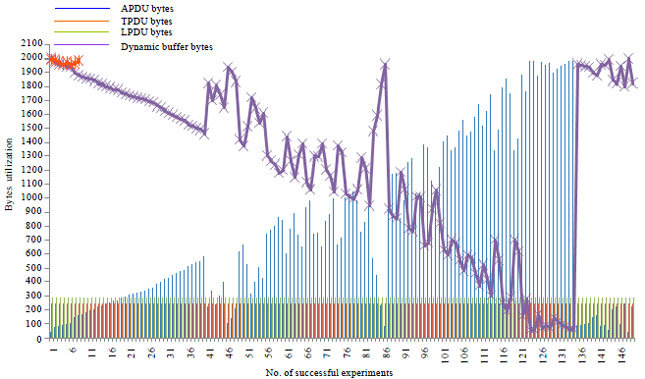
In Fig. 3, dynamic buffer size (bytes) has been increased as decreasing of APDU size (bytes) within DNP3 stack while Transport Protocol Unit (TPDU) and link protocol unit (LPDU) bytes are stable (constant) as 250 bytes and 292 bytes or assume that TPDU and LPDU bytes are fixed for each process (testbed experiment).
In Fig. 3, red markers show that 8 times dynamic buffer has been full and acquired extra memory space for cryptography implementation (storage). In this case, exception message has been executed and than 32 bytes from CRC (data link layer, user data blocks only) are shifted (move) to dynamic buffer (memory space). Thus, these 32 bytes are further utilized for cryptography deployment within DNP3 protocol. Figure 4, shows the dynamic buffer status while usage of extra 32 bytes from CRC (data link layer, user data blocks only).
RESULTS AND DISCUSSION
Dynamic buffer utilization and command response (bytes): The below bytes (RTU response), logical 107 bytes (response dummy bytes) have been reply back logically from RTU (sender or response) application layer to MTU (receiver) application layer. The below bytes (RTU application layer), are the response (bytes) transmitted from RTU to MTU while the heighted bytes show the application layer header or AH information, object header information and security information (proposed solution).
 | |
| Fig. 3: | Dynamic buffer bytes status (with exception) during communication |
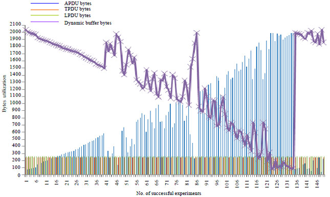 | |
| Fig. 4: | Dynamic buffer bytes status (without exception) during communication |
 | |
| Fig. 5: | Communication between DNP3 protocol stack (request/response bytes) |
Response APDU bytes (logical) are presented as follows:
 |
The heighted byte, 0x00c3 is application control information and 0x0081 is the function code (used for send response). Additional, two bytes 0x0000 and 0x0000 have been added within response message that distinguish the response message (bytes) header from request message (bytes) header. The internal indication or IIN (In response header fields) is two bytes fields follow by function code and used to send response message to master station. Each bit within IIN fields (11NS(1.0)__11NE(1.7) and 11NS(2.0)__11NE(2.7)) has specific meaning of sending response message.
The dynamic buffer implementation and bytes utilization process within response message (bytes) is identical as request message (bytes). Mean that whole dynamic buffer process is same within request and response message (bytes).
The bytes, 0x00ie and 0x0002 are designated for group and variation fields. The byte, 0x0000 is qualifier field which is used both in request/response message while data object are acquired (needed) from contiguous indexes. The bytes, 0x0004__0x0007 are designated for range fields. The reaming bytes 0x00e1, 0x000ee, 0x00a1, 0x00ee, 0x000a2 and 0x00ee are the cryptography information (bytes) which have been utilized for security implementation (proposed).
| Table 3: | Transfer _functions bytes with crytography implementation |
 | |
| Table 4: | Control _functions bytes with crytography implementation |
 | |
Pseudo-transport layer and data link layer specifications of response bytes (message construction) have been remain same in both cases; in the case of MTU send request to RTU or RTU send response to MTU. Figure 5 illustrates the logical communication of DNP3 protocol stack (Layers) between request bytes and response bytes.
DNP3 application layer has specified numbers of function codes (dnp.org) followed by Application Control (AC) field that has been added within message (message header) during MTU/RTU or RTU/MTU communication. Function codes define the specific function for data (bytes) being operated or what function to be operating on data. Some functions are limited for specific data (bytes) on which, they are operates. Table 3-9 show the several functions deployment (utilization) in both cases; In the case of MTU send request to RTU and RTU send response to MTU (DNP3, 2005). Function codes are added within application layer header or AH without interaction of pseudo-transport layer and data link layer. The highlighted or colored cells in Table 3-9 show that the specified operations are not employed during SCADA/DNP3 transmition. The application layer functions deployment within message (request and response) has been distributed into following main parts:
| • | The function bytes (codes) 0x0000, 0x0001 and 0x0002, are the transfer_functions bytes (codes). These functions define data objects for transferring information (data) between master station and remote station (Read function) and/or remote station and master station (Write function). Table 3 show the deployment of transferring functions bytes (codes) in both MTU send request (message) and RTU send response (message) with security bytes (cryptography solution) |
| • | The function bytes (codes) 0x0003, 0x0004, 0x0005 and 0x0006 are the control_functions bytes (codes).These functions are used to manage (operate) remote station control points (coming from field devices) depending on master station request. Table 4, show the deployment of control functions bytes(codes) in both MTU send request (message) and RTU send response (message) with security bytes (cryptography solution) |
| Table 5: | Freeze _functions bytes with crytography implementation |
 | |
| Table 6: | Application_control _functions bytes with crytography implementation |
 | |
| • | The function bytes (codes) 0x0007, 0x0008, 0x0009, 0x000A, 0x000B and 0x000C are the freeze_functions bytes (codes). These functions are used to record (store) system state values at regular session. The deployment of freeze functions bytes (codes) in both MTU send request (message) and RTU send response (message) with security bytes (cryptography solution) are shows in Table 5 |
| Table 7: | Configuration _functions bytes with crytography implementation |
 | |
| Table 8: | Time_synchronization _functions bytes with crytography implementation |
 | |
| • | The function bytes (codes) 0x000D, 0x000E, 0x000F, 0x0010, 0x00011 and 0x00012 are the application_control_functions bytes (codes). These functions are used to control the applications such as restart, initialization and start/shop. The deployment of application control functions bytes(codes) in both MTU send request (message) and RTU send response (message) with security bytes (cryptography solution) are shows in Table 6 |
| • | The function bytes (codes) 0x0013, 0x0014, 0x0015 and 0x0016 are the configuration_functions bytes (codes). These functions are used to configure the states (bytes state) such as save, enable/disable and class assignment while based on system behavior. Table 7 show the deployment of configuration functions bytes(codes) in both MTU send request (message) and RTU send response (message) with security bytes (cryptography solution) |
| • | The function bytes (codes) 0x0017 and 0x0018 are the time_synchronization_functions bytes (codes). These functions are used to manage (measure) session within communication (between stations). Table 8 show the deployment of time synchronization functions bytes (codes) in both MTU send request (message) and RTU send response (message) with security bytes (cryptography solution) |
| • | The function bytes (codes) 0x0019, 0x0001A, 0x001B, 0x001C, 0x001D and 0x001E are the file_functions bytes (codes). These functions are used to handle file states such as open, close, delete, get status, check security and abort. The function bytes (codes) from 0x0020 to 0x0080 are reserved and code 0x001F is uses for activate configuration (under development). Table 9 show the deployment of file synchronization functions bytes (codes) in both MTU send request (message) and RTU send response (message) with security bytes (cryptography solution) |
| Table 9: | File_functionsand response _functions bytes with crytography implementation |
 | |
| • | The function bytes (codes) 0x0000 (confirmation), 0x0081 (response) and 0x0082(unsolicited response) are the response bytes (codes) and used within response message (remote station send response to master station). The response functions (codes) are also shows in Table 9 |
CONCLUSION
This study has been implemented a novel solution designated as “Dynamic Cryptography Buffer (DCB)” within Distributed Network Protocol (DNP3) stack while existing security solutions used external memory (space), during end-to-end implementations. In proposed study, the cryptography mechanism as additional security layer (or layers) is successfully deployed within DNP3 protocol stack and the performance results show that the “Dynamic Cryptography Buffer (DCB)” allocated space is sufficient for security implementation. This study gives new security trends to implement and test the cryptography algorithms as a potential security solution, within DNP3 protocol as a part of SCADA system.
In future work, the “dynamic cryptography buffer” will implement and test in other SCADA protocols (stacks) such as Modbus, Fieldbus and other, because the initial design of these protocols are also without any security concerned.
REFERENCES
- Musa, S., A.A. Shahzad and A. Aborujilah, 2013. Secure security model implementation for security services and related attacks base on end-to-end, application layer and data link layer security. Proceedings of the 7th International Conference on Ubiquitous Information Management and Communication, January 17-19, 2013, Kota Kinabalu, Malaysia.
CrossRef - Shahzad, A.A., S. Musa, A. Aborujilah and M. Irfan, 2014. A new cloud based supervisory control and data acquisition implementation to enhance the level of security using testbed. J. Comput. Sci., 10: 652-659.
Direct Link - Musa, S., A.A. Shahzad and A. Aborujilah, 2013. Simulation base implementation for placement of security services in real time environment. Proceedings of the 7th International Conference on Ubiquitous Information Management and Communication, January 17-19, 2013, Kota Kinabalu, Malaysia.
CrossRef - Shahzad, A.A., S. Musa, A. Aborujilah, M.N. Ismail and M. Irfan, 2013. Conceptual model of real time infrastructure within cloud computing environment. Int. J. Comput. Networks, 5: 18-24.
Direct Link - Shahzad, A.A. and S. Musa, 2012. Cryptography and authentication placement to provide secure channel for SCADA communication. Int. J. Secur., 6: 28-44.
Direct Link - Shahzad, A.A., S. Musa, A. Aborujilah and M. Irfan, 2014. Industrial Control Systems (ICSs) Vulnerabilities analysis and SCADA security enhancement using testbed encryption. Proceedings of the 8th International Conference on Ubiquitous Information Management and Communication, January 8-10, 2014, ACM, New York, USA.
CrossRefDirect Link