
R.M. Kuppan Chetty
School of Engineering, Monash Univeristy Sunway Campus, Malaysia
T. Nagarajan
Department of Mechanical Engineering, University Teknologi PETRONAS, Malaysia
Noh Bin Karsiti
Department of Mechanical Engineering, University Teknologi PETRONAS, Malaysia
M. Singaperumal
Department of Mechanical Engineering, Indian Institute of Technology Madras, India
Journal of Applied Sciences
Year: 2012 | Volume: 12 | Issue: 24 | Page No.: 2494-2502


ABSTRACT
Modeling and simulation is an important activity in the development of complex control systems such as the multi-robot formation control. This study addresses the use of state based approach to model the complex systems that are employed to perform tightly coupled tasks in an unknown environment. The proposed state based model represents the entire behavior of the complex system by a global state machine or Augmented Finite state machines, which describes the complete intra-object behavior of the system. The methods to model and implement the state machines in the MATLAB-simulink/Stateflow environment are also addressed in this paper. Further, performance of the modeling approach is investigated through simulation studies by considering the multi-robot formation combined with navigation and role switching and are addressed in this study. The simulation result suggests that the state based model and simulation based on Stateflow could be a viable method to model mutli-domain systems such as the highly complex robotic systems with visualization, performance and formalism.
PDF Abstract XML References Citation
Received: September 02, 2012;
Accepted: November 02, 2012;
Published: January 10, 2013
How to cite this article
R.M. Kuppan Chetty, T. Nagarajan, Noh Bin Karsiti and M. Singaperumal, 2012. State Based Modeling and Control of a Multi Robot Systems Using Simulink/Stateflow. Journal of Applied Sciences, 12: 2494-2502.
DOI: 10.3923/jas.2012.2494.2502
URL: https://scialert.net/abstract/?doi=jas.2012.2494.2502
DOI: 10.3923/jas.2012.2494.2502
URL: https://scialert.net/abstract/?doi=jas.2012.2494.2502
INTRODUCTION
Robotics is a complex engineering field, dealing with design, modeling and control of highly intelligent systems, where the fascination to enter the field becoming increasingly popular. At the meantime their applications also increases where they find major roles from toys, domestic and industrial robots to sophisticated space application with the advancement in the complexity of the embedded systems. Robotics being a multi domain problem, therefore, modeling and simulation of such systems requires high artifacts in their conceptual design phase rather than their physical implementation model (Morzek, 2003). Overall such conceptual design is difficult to achieve since they tend to be very complex in nature and most of the currently using modeling and simulation tools operate on a traditional single domain approach (Goodman et al., 2002; Hing and Musa, 2008), without intensive interaction and integration between the different entities of the robotic system. As a result it is necessary to have the conceptual design of such systems where the solution concepts are selected and modeled and they are interconnected to achieve their elaborated performance as a complete integrated system. These solutions of concepts are designed or modeled based on the functional and behavioral synergy and by formal representation during the conceptual design stage rather than physical structuring. Morzek (2003) and Erden (2011) proposed two different approaches namely visual modeling with Unified Modeling Language (UML) and Petri Net based Design Network, for modeling multi domain reactive systems respectively. However, modeling and integration of energy, material and information flow has different qualitative structures and lacks formal modeling in such systems. In addition, manipulation of conceptual design solutions of a robotic system results in considerable effort for modeling the behavior or motion states, which exhibit highly reactive characteristics in nature (Erden, 2011). Moreover, systems possessing with such reactive characteristics are also considered as a hybrid systems, which can be modeled using state based techniques which have higher formalism in design (Arkin, 1998).
State based modeling is such a technique, which is used to model complex systems made up of reactive approaches. State based models is often used to represent the entire behavior of such system, for instance either by a global state machine or by a set of communicating state machines in which each state machine describes the complete “intra-object" behavior of a complex system. The functional interactions between the state machines are investigated in terms of state transitions in the system either with discrete behaviors modeled by Finite State Machines or the continuous behaviors modeled algebraically by the use of differential equations.
As a case study to prove the effectiveness of the state based modeling or conceptual design approach, the main objective of the present study is to model a multi-robot formation framework combined with navigation and obstacle avoidance. The task achieving behaviors of such systems, as represented (Chetty et al., 2011), is modeled using finite state machines augmented with timers, in a predefined scenario which constitutes an action when certain environmental factors occurs in the workspace of interest. These behaviors are modeled as combination of discrete event systems using AFSM and continuous behavior as differential equations based on their objectives and goals. In these modeling, the actions are modeled as state transitions and the environmental effects as events. In order to investigate the performance of these modeling methods, simulation studies are carried out in stateflow simulation environment, which is used for simulating event driven systems and the methods to implement these models are addressed in detail.
STATE BASED MODELING
The detailed description of the state based conceptual modeling methods of a Multi robot formation control system is presented here.
State based modeling is a modeling concept used to specify the complex hybrid control systems where the entire objective of the system is divided into set of functional task achieving behaviors/motion states working on individual goals concurrently and asynchronously, which upon integration yields the global objective of the system. Therefore, this kind of modeling method is used to model the task achieving behaviors and layers of the complex robotic systems. For readers understanding, this paper considers the formation control framework for multi robot control addressed in kuppan (Chetty et al., 2011) and mentioned in the previous section as a case study.
In state based modeling, when applied for multi robot control, the first step is to properly express the task achieving behaviors/states and the behavioral layers based on the overall functionality of the robots in the group. Several methods such as Stimulus-Response (SR) diagrams, functional notation and Finite State Machines (FSM) were available in the literature (Arkin, 1998) to model the individual task achieving behaviors/motion states of the reactive control system. However, the task achieving behaviors of the entire layered formation framework is represented as Finite State Machines augmented with timers, called Augmented Finite State Machines (AFSM). The use of AFSMs results in a tight coupling of perception and action, producing the highly reactive response characteristic of the complex behavioral control systems where entire sets of primitive (task achieving) behaviors are swapped in and out of execution during the accomplishment of higher-level goal. Further, they are very useful when describing sequence of behaviors and they make explicit the behaviors/motion states active at any given time, the transitions between them and to hold internal data structures of the system.
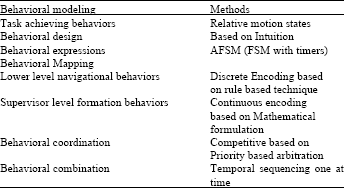
The next step is to realize the input-output relationship of the task achieving behaviors and to functionally map the inputs from the stimulus plane to the motor plane, to have the behavioral response. This is accomplished by incorporation of suitable behavioral transformation function βi, for the individual task achieving behaviors, where the behavioral response is activated when the inputs from the sensors (λ) exceed the predetermined threshold level (τ). By altering the value of (τ) in correspondence with the task achieving behavior, one can alter the trigger of response of the task achieving behavior over the stimuli. Hence, the method to create this kind of functional mapping of the stimulus plane to motor plane is called as the behavioral encoding/mapping. Associated with a particular behavior, the behavioral mapping function β determines the robotic motor responses, which may fall into three major categories such as Null, Discrete and Continuous. Among all the above mapping functions, discrete behavioral mapping is used since the task achieving behaviors have a finite set of stimulus and response pairs.
Further, the sequence of actions for responses generated by this mapping function for a situation is very simple and reduces the complexity of the system model as in the case of continuous encodings formed by a mathematical function, which transforms the sensory input to behavioral activation function. Hence, an IF- Then rule based technique is used for representing the behavior mapping function (β) of the task achieving behaviors such as avoid obstacle, safe wander and Pit sensing present in the navigational part of the formation framework. The major advantage of this rule-based technique is that at any instant more than one rule may be used for any given situation that corresponds to the set of responses of the behaviors. However, the continuous encoding is used as the behavioral mapping function (β) for the supervisor level formation, since the objective of the tracking controller is to make the robots to be in the desired formation with its teammates. Hence (β) is made up of mathematical formulation of the kinematics of the robots employed, as addressed in kuppan (Chetty et al., 2011).
Finally, it is important to apply a suitable coordination and communication mechanism to coordinate the task achieving behaviors/motion states, to yield the global objective of robot control. Having discussed methods to describe individual behaviors, when multiple behaviors/AFSM is employed to construct the system, it is necessary to coordinate the emergent behavior to have the response signal for the robotic motor actuator. Here the coordination mechanism plays a major role as the selector/arbiter which selects the particular active behavior. There are two primary mechanisms for behavioral coordination, which are competitive and cooperative. In this work the competitive methods especially priority based arbitration mechanism is used as the arbiter to select the active behavior. A strict behavioral dominance hierarchy exists, typically through the use of suppression which is a hall mark of subsumption based architectural methods developed by Brooks (1990). With the above inputs in the state based modeling technique, the active behaviors or motion states of the multi-robot system such as the ‘proceed’, ‘Avoid obstacle’, ‘Safe wander’, ‘Pit sensing’ classified into lower level navigational part and ‘formation’ as the supervisory level, are modeled as given in Table 1. The details of the emergence of these behaviors or motion states could be referred in the work reported by kuppan (Chetty et al., 2011).
With these inputs, the behaviors or motion states of the robots are modeled and expressed in state based model as triples as:
| (1) |
where, * is the vector encoding the global responses undertaken by the robot; G= [g1, g2, g3 …..]T is the vector encoding gain of each behavior βi, ; B is the Vector of all active behavior βi at time‘t’, B= [β1, β2, β3…]T ; S= [s1, s2, s3…]T is the vector of all stimuli si for each behavior at time t; and C is the Coordination/arbitration function which is competitive or cooperative.
IMPLEMENTATION IN SIMULINK/STATEFLOW ENVIRONMENT
State flow is an interactive graphical design and development tool that works with Simulink to model and simulate complex systems modeled as finite state machines, also called reactive event driven systems.
| Table 1: | Methods of Modeling task achieving behaviors |
 | |
Event-driven systems transit from one operating mode to another in response to events and conditions. The corresponding systems are called discrete-event dynamic systems and are often used to model logic for controlling a physical device such as a robot. Advantage of the state flow over traditional Matlab-Simulink and other simulation environment is the availability of graphical objects, where the finite state machines are designed as state transition charts. The series of state transitions directs a flow of logic from one state to another state. Hence, Matlab-Simulink/Stateflow environment is used as the simulation environment to measure the performance of the layered control approach (Brooks, 1990; Stormont and Chen, 2005).
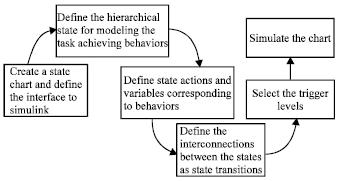
In Stateflow simulation environment, several steps are to be followed to develop the state chart model for the reactive control architecture as given in Fig. 1.
First step is to create a simulink model, which defines the interface of the state chart to the necessary inputs from and the outputs to the simulink environment. The sensory information is created as discrete events and data, in the signal builder of the simulink environment and provided as input to the behavioural layers. The next step is to define the hierarchical states, which are the group of task achieving reactive behaviors/finite sate machines of the control system. Third step is to define the actions and a variable corresponding to the task achieving states while entering and exiting the states or while in active. This gives the response of the active state. Finally, the Interconnections between the states are created/modelled as state transitions that are represented by lines with arrowheads, where the transitions from one state to another state occurs based on the sensory information.
In the Simulink-state flow environment, in general, the task achieving behaviours/AFSM are modelled as temporal states. These states can be of parallel and states with dotted rectangles or sequential OR states with solid rectangles, with round corners as shown in Fig. 2.
 | |
| Fig. 1: | Different steps used for development of state chart model |
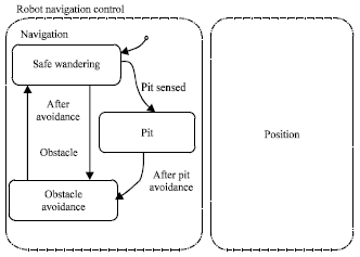 | |
| Fig. 2: | State chart representation of robot system |
The position state is the virtual state implemented in parallel with navigational state, in order to update the posture information of the robot irrespective of the behaviours/states that the robot executes while navigating the environment. Hence, the temporal states of Navigation and Position are implemented as parallel and states in the environment. The individual task achieving behaviours of the navigational state such as obstacle avoidance, safe wander and pit sensing are created as sequential OR states in the simulation environment. Interconnections between the states are modelled as state transitions that are represented by lines with arrowheads, where the transitions from one state to another state occur based on the sensory information and the state transition conditions. The arrow heads represents the flow transition from one state to another. The arrowheads with the dotted end represent the default/initial behaviours/states of the model. The sensory information is created as discrete events and data, in the signal builder of the simulink environment and provided as input to the behavioural layers through state flow chart.
Obstacles and pits in the environment are modelled such that the sensors provide a logically high signal in the time frame whenever it perceives the obstacle and pit information and present them as inputs to the robots. The avoid obstacle behavioural response for the sensory events is modelled such that the robots make a change in orientation by prescribed ‘θ’ degrees. This in turn changes its direction of motion towards left or right based on the position of the obstacles with respect to the current posture of the robot. For the pit sensing behaviour, the response of the behaviour is modelled such that initially it backs up for a distance of ‘d’ and starts to navigate the environment by changing its direction towards left or right. Based on the sensory information and the conditions, the control to the robot actuator takes place by switching the task achieving behaviours/states in out of execution by means of suitable state transitions.
Implementation of the multi-robot formation control model in the stateflow simulation environment is shown in Fig. 3. Three robots R1, R2 and R3 are employed in the formation framework and they are modelled as parallel AND states to have identical control architecture as mentioned in the previous section. These AND states consist of two temporal states which are the representation of the individual lower level navigation and supervisor level formation layers. As mentioned earlier, the sub states of the navigation and formation are implemented as sequential OR states with priority and interconnected with suitable state transition functions. State transition between the navigational and formation behaviour is carried out based on the obstacle information perceived by the follower robot and the communication mechanism.
For example, w.r.t Fig. 2, the entry variable of the avoid obstacle behaviours are the range and angular orientation of the obstacle perceived by the robot sensor with respect to the current pose of the robot. The output of the behaviour is the motor control data which is generated by the while execution of the corresponding active obstacle avoidance state. Similarly, for the behaviour of safe-wander, the entry variables are the sensor data, time and the previous direction of turn and the exit variables are the motor control data which directs the robot motion.
By default, in the simulation model represented by Fig. 3, the Robot R1 has the highest priority over the other robots in the group to gain the leadership and executes the navigational behavior. The other robot such as R2 and R3, as shown in the formation framework mentioned above takes the role as the follower and executes the formation state. The formation state has the tracking controller developed in the present work, as its behavioral transformation function. The entry variables of this formation behaviour are the posture and velocity information of the leader robot R1 obtained by means of inter-robot communication mechanism. In addition, the desired linear and angular separation between the robots, which depicts the topology of formation, is also provided as the entry variables. The exit variables are the current pose of the robot R2 designated as the follower. The response output of the corresponding behaviour is the separation errors and the motor control data, which are obtained as the result of execution of the state by the conditions that are given (Chetty et al. 2011).
 | |
| Fig. 3: | State modeling and implementation of layered control architecture in the simulation environment for three robots in closed defined formation |
 | |
| Fig. 4: | State modeling and implementation of layered control architecture in the simulation environment for three robotsoutputs, formation errors and postures of both the robots are recorded and are interconnected with the simulation environment for data logging |
The control out puts, formation error and postures of both the robots are recorded and are interconnected with the simulation environment for data logging.
One of the important aspects of the proposed formation control approach is the active obstacle avoidance of the path of the follower robots, which is accomplished by the incorporation of dynamic switching of roles by means of exchange of leadership between the robots. The methodology adopted for such strategy is given (Chetty et al., 2011).
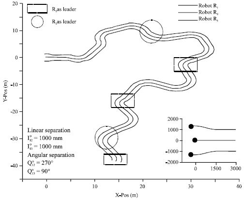 | |
| Fig. 5: | Trajectory of robots in the workspace exhibiting dynamic switching of roles |
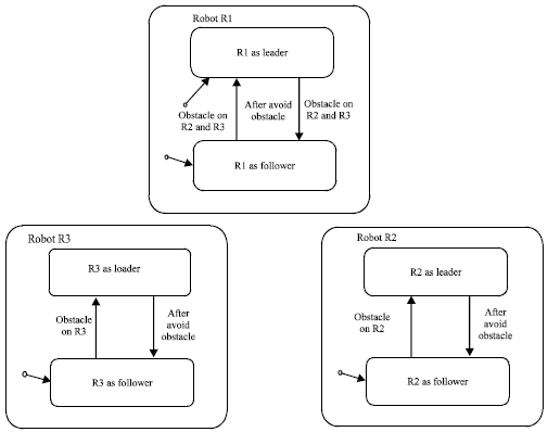
Figure 4 shows the execution of formation behaviors and how the dynamic switching of roles between the robots is implemented in the state flow environment in detail, when Robot R2 acts as follower and obstacle is on R2 or R3 or on both R2 and R3. The follower state has three sub states such as Robot R1 as leader, Robot R3 as leader and a temporary state. These states are selected and implemented to avoid the confusion of the robot R2, to gather the parameters of its corresponding leader at that instant, which are to be given as the inputs to the tracking controller. By default, robot R1 acts as leader and at any instant Robot R3 can become the temporary leader, if it perceives an obstacle in its path. Therefore, at any instant, there can be only one leader either R1 or R3 to the robot R2 during the formation framework. The transitions between the states are represented by guarded state transitions.
Initially during the formation framework and assuming Robot R1 acts as the leader, the robot R2 executes the state ‘Robot R1 as leader’. This in turn executes the formation behavior and keeps the robot R2 in closed defined formation with the leader. When the robot R3 gains the leadership from the robot R1, robot R2 executes the formation behavior by switching the state from ‘Robot R1 as leader’ to ‘Robot R3 as leader’ by means of the state transition function guarded by the discrete event ‘Obstacle on R3’.
Simulation results: Simulation studies have been carried out to test the performance of the control architecture for the combined objective of guiding the group of mobile robots in the closed defined formation as a whole, while navigating the environment by avoiding obstacles on their paths. However, the principles behind the control architecture are not simulated. In all the simulation studies that are performed, the robot running environment is selected to measure all possible reactive behaviors/motion states of the layered framework without the boundary conditions imposed in the simulation environment. Sensory signals are created such that they produce high signals whenever they perceive obstacle or pits in the environment, using the signal builder block of the Simulink. Wheel velocities, wheel direction of rotation and the position and orientation information of the robots are taken as the behavioural outputs and are logged into the data loggers. Simulation parameters and the threshold values for the behavioural activation are provided in the simulation environment taking the kinematics of the robots into account. The wheel velocities obtained as behavioural outputs are constrained and bounded by the conditions v <vmax <300 mm/s and ω < ωmax <50°/s.
Figure 5 to 7 show the results of the simulation studies in state flow that are carried out to measure the performance of the Multi robot systems modelled using state based technique. Figure 5 shows the trajectories of three robots in a closed defined formation having the desired linear and angular separation between them during the fly while navigating the environment. Further, it can also be observed form the encircled portion of the figure, that the state transition in the model makes the robots to switch their roles in order to avoid the obstacles in their path, without disturbing the spatial pattern between the robots R1, R2 and R3. The sensory information for robots R1, R2 and R3 representing the obstacle and pit in the environment are created as logical high signal in the simulation environment as shown in Fig. 6.
Figure 7 shows the emergence of individual behaviours of the robots R1, R2 and R3 as state outputs, whenever the robots perceives the sensory information given by Fig. 6. The ‘logical 1’ represents the emergent states that are active at that time instant to have control over the robot.
It could be observed from the above result that the state based modeling through motion states of the robot provide efficient control in achieving the overall task of the robot by switching the states based on the sensory perception.
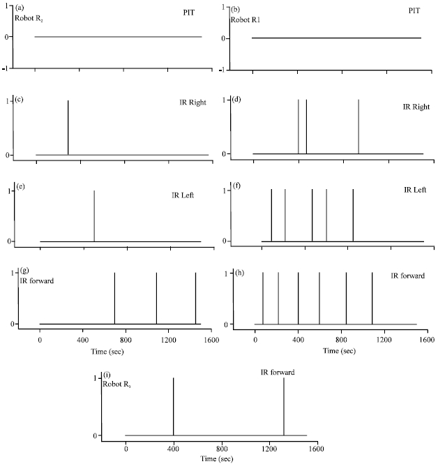 | |
| Fig. 6(a-i): | Sensor signals of robots modeled as logic high in Signal builder of Simulink |
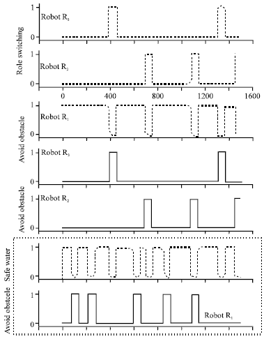 | |
| Fig. 7: | Sensor signals of robots modeled as logic High in Signal builder of simulink |
The switching of motion states in and out of execution through the state transition routes the response of the emergence behavior to the robot actuator, which governs the motion of the robots.
CONCLUSION
In this study, a state based modelling methodology is addressed to model the complex reactive multi domain systems. The proposed state based model represents the entire behavior of the complex system by a global state machine or Augmented Finite state machines, describing the complete intra-object behavior of the system. The multi robot formation approach is considered as a case study and it is modeled using the state based method and the implementation of such model as state charts in Simulink/Stateflow is also addressed in this paper. The efficiency of the modeling method is also investigated through simulation studies and it is found out that the Stateflow specifies the complete behavior of the system using the state chart formalism without considering the physical nature of the system. Therefore it is evident that any multi-domain system could be modeled with visualization, performance and formalism.
ACKNOWLEDGMENT
First author would like to thank Robotics Automation and Manufacturing research strength of Monash University Sunway Campus for providing the opportunity to visit IIT Madras, India as visiting researcher to carry out this work. Author would also like to thank Precision Engineering and Instrumentation laboratory of IIT Madras, for offering visiting researcher position. Further, Authors would also like to thank Ministry of Higher Education (MOHE), Malaysia to support this work through the project Exploratory Research on the behavior based planning and control of formations in WMR.
REFERENCES
- Morzek, Z., 2003. Computer aided design in mechatronic systems. Int. J. Appl. Mathe. Comput. Sci., 13: 255-267.
Direct Link - Erden, Z., 2011. State-based conceptual design in mechatronics via petri nets: A case study for an educational robot. CEAI, 13: 70-75.
Direct Link - Chetty, R.M.K., M. Singaperumal and T. Nagarajan, 2011. Distributed formation planning and navigation framework for wheeled mobile robots. J. Applied Sci., 11: 1501-1509.
CrossRef - Stormont, D.P. and Y.Q. Chen, 2005. Using mobile robots for controls and mechatronic education. Int. J. Eng. Educ., 21: 1039-1042.
Direct Link - Hing, T.H. and M. Musa, 2008. Simulator for control of autonomous nonholonomic wheeled mobile robot. J. Applied Sci., 8: 2534-2543.
CrossRefDirect Link