
M. Khavarian
School of Chemical Engineering, Universiti Sains Malaysia, 14300, Nibong Tebal, Pulau Pinang, Malaysia
S. P. Chai
School of Engineering, Monash University, Jalan Lagoon Selatan, 46150, Bandar Sunway, Selangor, Malaysia
S. H. Tan
School of Chemical Engineering, Universiti Sains Malaysia, 14300, Nibong Tebal, Pulau Pinang, Malaysia
A. R. Mohamed
School of Chemical Engineering, Universiti Sains Malaysia, 14300, Nibong Tebal, Pulau Pinang, Malaysia
Journal of Applied Sciences
Year: 2011 | Volume: 11 | Issue: 13 | Page No.: 2382-2387


ABSTRACT
Carbon nanotubes (CNTs) were synthesized by a Floating Catalyst (FC) chemical vapor deposition (CVD) method in a horizontal reactor. This method led to achieve high yield synthesis of CNTs with controlled structure. Present study showed that iron (III) chloride hexahydrate (FeCl3. 6H2O) was an efficient FC precursor for CVD of methane into CNTs. The effects of different process parameters such as reaction temperature and reaction time on the morphology of CNTs had been investigated. The deposited layers containing CNTs and CNFs were analyzed by the Transmission Electron Microscopy (TEM) and the yield of the as-grown nanotubes was investigated by the thermogravimetric analysis (TGA).
PDF Abstract XML References Citation
Received: February 15, 2011;
Accepted: February 19, 2011;
Published: May 28, 2011
How to cite this article
M. Khavarian, S. P. Chai, S. H. Tan and A. R. Mohamed, 2011. Effect of Different Parameters on the Morphology of Carbon Nanotubes Structures Grown by Floating Catalyst Method. Journal of Applied Sciences, 11: 2382-2387.
DOI: 10.3923/jas.2011.2382.2387
URL: https://scialert.net/abstract/?doi=jas.2011.2382.2387
DOI: 10.3923/jas.2011.2382.2387
URL: https://scialert.net/abstract/?doi=jas.2011.2382.2387
INTRODUCTION
Since the discovery by Iijima (1991), carbon nanotubes (CNTs) have been receiving much more attentions for their unique structural, mechanical and electronic properties. Extensive research work on the synthesis of CNTs, including laser-ablation (Thess et al., 1996), electric arc discharge (Journet et al., 1997) and Chemical Vapor Deposition (CVD) (Endo et al., 1995) has been carried out to produce high quality CNTs for the applications in electronic, mechanical and gas storage fields. More research efforts have been put to reach the economical ways of synthesis with much greater control over the key characteristics such as length and diameter. Among the distinguished variant techniques of CVD, Floating Catalyst (FC) is considered to be the most promising commercial method for producing high purity CNTs because of the attribute of possible continuous producing by a simple equipment set-up (Fan et al., 2006). Therefore, FC-CVD is a suitable approach for industrial production of high purity CNTs at low cost. Besides CNTs, carbon nanofibers (CNFs) can also be synthesized by the FC-CVD process. CNFs are important materials that can substitute CNTs in some applications in view of CNFs are much easy to be commercially produced (Bai et al., 2003). However, a systematic study of the process parameters for FC-CVD needs to be developed. The yield, length and purity of CNTs produced by this method have been found to depend on the reaction temperature, type of catalyst precursor, type of reactant, reaction time and reactant flow ratio. Up to now, Ferrocene (Yang et al., 2008; Cheng et al., 2008) and Fe(CO)5 (Rao and Govindaraj, 2002; Andrews et al., 1999) are the common FC precursors. On the other hand, FeCl3.6H2O (the transition metal salts) has been explored to synthesize CNTs in the CVD method. It was reported by Hou et al. (2003) that a dilute solution of FeCl3 in toluene and N,N-dimethylaminoacetate shows high-efficiency for CNTs synthesis.
In this study, we report a simple FC-CVD method to prepare CNTs in a horizontal reactor, i.e., using iron (III) chloride hexahydrate (FeCl3.6H2O) as the FC precursor and methane as the carbon source. The main objective of this study was to investigate the influence of reaction temperature and synthesis time on the morphology of the CNTs grown. CNTs with different diameters can be prepared by carefully controlling the reaction temperature. The as-grown CNTs were characterized by Transmission Electron Microscopy (TEM), thermogravimetric analysis (TGA) and Differential Thermal Analysis (DTA).
MATERIALS AND METHODS
CNTs synthesis through FC-CVD: The synthesis of CNTs was carried out by the FC method in a horizontal tubular reactor made of quartz tube with a diameter of 25 and 900 mm in length. The reactor was inserted into a horizontal tubular furnace that can provide controllable heating temperatures up to 1200°C and a heating zone (reaction zone) of 550 mm in length. A schematic diagram of the FC-CVD apparatus is shown in Fig. 1. Methane was used as the carbon source, FeCl3.6H2O as the catalyst precursor and nitrogen as the carrier gas.
Two series of experiments were conducted: 1) The reaction temperatures were set at 1000, 1050 and 1100°C for 30 min reaction duration; 2) The reaction durations were set at 5 and 15 min for the reaction temperature at 1050°C.
A typical FC-CVD synthesis consists of the following apparatus and operations conditions:
| • | A quartz boat containing FeCl3.6H2O catalyst (about 0.3 g, spread over 50 mm2) was placed at the entrance of the tubular furnace (as shown in Fig. 1) |
| • | The reactor was purged with nitrogen gas at 200 mL min-1 for 10 min in order to evacuate air in the reactor |
| • | After the temperature reached 1000°C, methane gas was fed into the reactor at a volumetric flow rate of 200 mL min-1 for 30 min |
| • | The temperature of preheated zone for FeCl3.6H2O was measured by a set of K-type thermocouple thermometer in a range of 280-300°C. At these temperatures, the catalyst placed on the quartz boat was vaporized and carried forward by the nitrogen gas into the reaction zone. Iron catalyst decomposed from the FeCl3.6H2O was deposited on the wall of quartz tube and this act as a base for the growth of NTs |
| • | The methane gas was switched off after the reaction duration and the reactor was cooled down to the room temperature under the nitrogen flow |
| • | Some of the grown nanotubes were transported out of the reaction zone by the flowing reacted gases. The nanotubes were collected from the end of the quartz tube. A water bubbler was also placed at the end of the furnace to capture the CNTs and iron catalyst |
Nanotubes characterization: The morphology of FC-CVD synthesized products was analyzed with a Philips XL 20 Transmission Electron Microscope (TEM). For the TEM analysis, a drop of a sonicated acetone suspension of CNTs (0.1 mg mL-1) was deposited on a holey carbon TEM copper grid. The product purity and the yield of CNTs were determined by the thermogravimetric analysis (TGA) using SDT Q600 TA instruments Differential Thermal Analysis (DTA). The ramping was set rate to 10°C min-1 from room temperature to 900°C under 100 mL min-1 of nitrogen. Analysis was performed using the TGA data to estimate the relative amount of CNTs in the products.
 | |
| Fig. 1: | Experimental set-up of horizontal reactor to synthesis of CNTs |
The parameter, onset temperature, oxidation temperature and end temperature were determined from the TGA and DTA curves by the commercial software package.
RESULTS AND DISCUSSION
The reaction temperatures were conducted according to the reported by Kuo et al. (2005). In the present study, the experiments were conducted at the starting temperature of 1100°C. This is to ensure the complete decomposition of methane in the reactor. It is believed that the Fe3+ catalyst was reduced by the methane gas as well as the hydrogen produced from the methane decomposition. The observations of TEM show that CNTs synthesized with different reaction temperatures have different outer and inner diameters as shown in Table 1.
The degree of graphitization of the CNTs was studied using TGA/DTA (Chen et al., 2006) and the results are shown in Fig. 2. The onset, oxidation and end temperatures are listed in Table 2, representing the initial weight loss, the maximum weight loss and the final weight in the TGA/DTA graphs. Firstly, the sharp weight loss between onset and end temperature is due to the formation of CO and CO2 by oxidation of CNTs. Chen et al. (2006) proposed that the higher oxidation temperature indicates a better graphitized CNTs. According to the results shown in Fig. 2b, the highest oxidation temperature (643.88°C) was observed for the sample prepared at the reaction temperature of 1050°C.
There is no or slightly weight loss in the temperatures between 300 and 400°C as shown in Fig. 2a. This indicates that the content of amorphous carbon in the samples was very low. The weight loss occurred very gently before 300°C could be assigned to the moisture content of the carbon samples. The highest purity of CNT, being 80.96% was obtained at the reaction temperature of 1100°C. In every instance a black powder was obtained in yields of >74% CNTs.
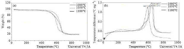 | |
| Fig. 2: | TGA/DTA results of CNTs growth with various reaction temperatures (a) TGA and (b) DTA |
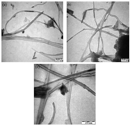 | |
| Fig. 3: | TEM micrographs of samples obtained after 30 min reaction at different temperatures°C (a) 1000, (b) 1050 and (c) 1100 |
| Table 1: | Effect of the reaction temperature on the outer and inner diameter of the CNTs |
 | |
| Table 2: | The TGA/DTA results of CNT growth at different reaction temperatures |
 | |
Reaction temperatures greatly affect the yield of CNTs from the FC-CVD. As previously-mentioned, the maximum yield was obtained at 1100°C. Figure3 (a-c) shows the morphologies of the CNT grown at temperatures 1000, 1050 and 1100°C, respectively.
As shown in Fig. 3a, amorphous carbon was also found for the samples synthesized at reaction temperature 1000°C. This probably due to the activities of the iron catalyst particles decreased at low temperatures in which the, therefore decomposition of carbon reagents was poorly interacted with the iron catalyst. At higher temperatures (1100°C), amorphous carbon was again formed, but this time the formation of amorphous carbon was due to the decomposition of carbon on the CNTs, as can seen from the TEM images shown in Fig. 3c. At high temperatures, iron particles were aggregated because of the decrease in the density distribution of the iron particles. Probably this is the main reason to cause the formation of amorphous carbon on the nanotubes samples (Nyamori and Coville, 2007). It is important to note that three different types of carbon shaped observed, including were CNFs, CNTs and amorphous carbon.
The sizes of the CNTs were strongly governed by the variation in temperature. The change in temperatures from 1000 to 1100°C formed CNTs with larger diameters. This was mainly due to the extensive aggregation of the iron particles at high temperatures, leading to the formation of larger catalyst particles and hence contributing to grow CNTs of larger diameters. However, outer diameters of CNTs were found to be smaller at 1000°C as compared to those synthesized at 1050 or 1100°C. In Fig. 3a and b, one can note that the CNTs consist of the aggregated graphitic tubes with the average inner diameters of 8 and 21 and outer diameters of 27 and 43 nm, respectively. Figure 3c shows the CNTs of the average inner and outer diameters of 20 and 71 nm, respectively grown at 1100°C. CNFs, amorphous carbon and residual catalytic metal particles are also present in the samples.
In the second series of experiments, the influence of synthesis time on the morphology of powder deposits was studied using TEM. From the TEM images shown in Fig. 4(a-c), it can be revealed that the nanotubes diameters vary from 33 to 50 nm. Apparently, the average diameter of CNTs was not affected by increasing the reaction time. The images also show numerous elongated encapsulated particles seated within the tube cavities. This means that the reaction time has no influence on the CNT diameter supports the idea that the nanotube diameter is dependent only upon the catalyst cluster size, but not the reaction time (Barreiro et al., 2006).
Figure 5a shows a catalyst particle encapsulated in the tips of the CNTs. Its diameter was a little larger than the inner diameter of the CNTs. The inner part of the wall of the CNTs became thinner towards the tips of the particle. The outer part of the wall was also larger at the end of nanotube. The degree of hollowness of the CNTs increased due to the existence of Cl content in the catalyst precursor, hence it provides a convenient way to control the morphology of CNTs (Lv et al., 2007). As shown in Fig. 5b it was frequently observed the sitting of the catalyst particles inside the CNTs thus connected to the inner tube cavity.
The inner part of CNTs growth process obeys the vapor-liquid-solid (VLS) growth mechanism. Firstly, the iron atoms decomposed from FeCl3.6H2O formed small iron particles in the furnace. Transition metal catalyst especially iron has the best solubility of carbon atoms (Moisala et al., 2003). Thus, after decomposition of FeCl3.6H2O the iron atoms in the gas phase will collide with carbon atoms which decomposed from methane. Then the aggregation from this collision is the main reason of the aggregation and condensation of the iron catalyst particles (Nyamori et al., 2008). Hence, gaseous phase of iron catalyst will be change to liquid particles floating in the reaction zone. Compared with the growth mechanism in that suggested that the carbon atoms diffused from the surface of the solid form catalyst particles (Renshaw et al., 1970), the carbon atoms diffused through the liquid catalyst particles in present experiments. When the catalyst particles became supersaturated, the inner core of the CNTs began to precipitate on one side of the particles because of the gradient in chemical potential (Bai et al., 2003). CNTs could grow with their tips open during their growth process. Once an iron catalyst particle falls on the tip, the nanotube begin to grow and grab the iron particles inside the narrow cavity of CNTs as shown in Fig. 5b. Also during the growth of CNTs, the iron particle is deformed due to the squeeze of the nanotube tip.
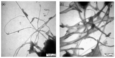 | |
| Fig. 4: | TEM micrographs of samples synthesized at 1050°C for (a) 5 min, (b) 15 min |
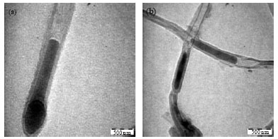 | |
| Fig. 5: | TEM image of catalyst particle encapsulated (a) in the head of the CNTs and (b) inside of the CNTs |
A new circulation of growing CNTs starts, until one new iron catalyst particle falls on the open tip. Finally the particle stops rising and is circled by the nanotube wall. The reason maybe that the iron catalyst particle loses its catalytic activity, and/or the adherence strength between the particle and the wall is higher than the push force of the nanotube tip (Zhang et al., 2002). The catalyst particles would be inactivated when their temperature was low and the inner core growth process stopped.
CONCLUSION
CNTs synthesis was carried out at 1000, 1050 and 1100°C in a horizontal quartz reactor via FC-CVD approach, using methane and nitrogen as the hydrocarbon source and carrier gas, respectively. This study shows that applying FeCl3.6H2O as FC could produce high purity CNTs of narrow diameter distribution. In general, the diameters of the nanotubes fall in the range of 30-50 nm but most of the tubes having the diameters of ca. 40 nm. FeCl3.6H2O has some advantages for the synthesis of CNTs, such as easily volatilization, easily attainable, less toxicity and low price. The results showed that the reaction temperature and synthesis time have a great influence on the yield of CNTs produced from the FC-CVD process. It was also found that the reaction temperature plays a key role in the growth of CNTs, governing both the diameter and the yield of CNTs.
ACKNOWLEDGMENTS
The authors gratefully acknowledge the financial support provided by the Universiti Sains Malaysia (USM) under the Research University Grant Scheme (814003).
REFERENCES
- Andrews, R., D. Jacques, A.M. Rao, F. Derbyshire and D. Qian et al., 1999. Continuous production of aligned carbon nanotubes: A step closer to commercial realization. Chem. Phys. Lett., 303: 467-474.
CrossRef - Bai, S., F. Li, Q. Yang, H.M. Cheng and J. Bai, 2003. Influence of ferrocene/benzene mole ratio on the synthesis of carbon nanostructures. Chem. Phys. Lett., 376: 83-89.
CrossRef - Barreiro, A., D. Selbmann, T. Pichler, K. Biedermann and T. Gemming et al., 2006. On the effects of solution and reaction parameters for the aerosol-assisted CVD growth of long carbon nanotubes. Applied Phys. A Mater. Sci. Process., 82: 719-725.
CrossRef - Chen, C.M., Y.M. Dai, J.G. Huang and J.M. Jehng, 2006. Intermetallic catalyst for carbon nanotubes (CNTs) growth by thermal chemical vapor deposition method. Carbon, 44: 1808-1820.
CrossRef - Cheng, J., X.P. Zou, G. Zhu, M.F. Wang and Y. Su, 2008. High-quality single-walled carbon nanotubes synthesized by floating catalyst chemical vapor depostion. Adv. Mater. Res., 47-50: 746-749.
CrossRefDirect Link - Hou, H., A.K. Schaper, Z. Jun, F. Weller and A. Greiner, 2003. Large-scale synthesis of aligned carbon nanotubes using FeCl3 as floating catalyst precursor. Chem. Mater, 15: 580-585.
CrossRef - Endo, M., K. Takeuchi, K. Kobori, K. Takahashi, H.W. Kroto and A. Sarkar, 1995. Pyrolytic carbon nanotubes from vapor-grown carbon fibers. Carbon, 33: 873-881.
CrossRef - Fan, Y.Y., A. Kaufmann, A. Mukasyan and A. Varma, 2006. Single- and multi-wall carbon nanotubes produced using the floating catalyst method: Synthesis, purification and hydrogen up-take. Carbon, 44: 2160-2170.
CrossRef - Journet, C., W.K. Maser, P. Bernier, A. Loiseau and M.L. de la Chapelle et al., 1997. Large-scale production of Single-walled carbon nanotubes by the Electric-arc technique. Nature, 388: 756-758.
Direct Link - Kuo, C.S., A. Bai, C.M. Huang, Y.Y. Li, C.C. Hu and C.C. Chen, 2005. Diameter control of multiwalled carbon nanotubes using experimental strategies. Carbon, 43: 2760-2768.
CrossRef - Lv, R., F. Kang, W. Wang, J. Wei, J. Gu, K. Wang and D. Wu, 2007. Effect of using chlorine-containing precursors in the synthesis of FeNi-filled carbon nanotubes. Carbon, 45: 1433-1438.
CrossRef - Moisala, A., A.G. Nasibulin and E.I. Kauppinen, 2003. The role of metal nanoparticles in the catalytic production of single-walled carbon nanotubes: A review. J. Phys. Condensed Matter, 15: 3011-3035.
CrossRefDirect Link - Nyamori, V.O. and N.J. Coville, 2007. Effect of ferrocene/carbon ratio on the size and shape of carbon nanotubes and microspheres. Organometallics, 26: 4083-4085.
CrossRef - Nyamori, V.O., S.D. Mhlanga and N.J. Coville, 2008. The use of organometallic transition metal complexes in the synthesis of shaped carbon nanomaterials. J. Organometallic Chem., 693: 2205-2222.
CrossRef - Zhang, X., A. Cao, B. Wei, Y. Li, J. Wei, C. Xu and D. Wu, 2002. Rapid growth of well-aligned carbon nanotube arrays. Chem. Phys. Lett., 362: 285-290.
CrossRef - Rao, C.N.R. and A. Govindaraj, 2002. Carbon nanotubes from organometallic precursors. Acc. Chem. Res., 35: 998-1007.
CrossRef - Renshaw, G.D., C. Roscoe and P.L. Walker, 1970. Disproportionation of CO: I. Over iron and silicon-iron single crystals. J. Catal., 18: 164-183.
CrossRef - Thess, A., R. Lee, P. Nikolaev, H. Dai and P. Petit et al., 1996. Crystalline ropes of metallic carbon nanotubes. Science, 273: 483-487.
CrossRefDirect Link - Yang, Z., X. Chen, H. Nie, K. Zhang, W. Li, B. Yi and L. Xu, 2008. Direct synthesis of ultralong carbon nanotube bundles by spray pyrolysis and investigation of growth mechanism. Nanotechnology, 19: 085606.1-085606.8.
CrossRef