
Cemal Yilmaz
Department of Electrical Education, Faculty of Technical Education, Gazi University, Turkey
Journal of Applied Sciences
Year: 2010 | Volume: 10 | Issue: 14 | Page No.: 1449-1454


ABSTRACT
In this study, a home automation system controlled by a Programmable Logic Controller (PLC) was designed. The designed control module comprised of software and hardware. The control module provides multilevel component fault detection, tolerance, switch on or switch off in critical-areas such as gas sensing, voltage control of power socket and valve control circuits. The system is easy to build, service, modify and it provides reliable communication identified as an opportunity to reduce of home automation costs. The proposed system is easily programmable to demand adding different home appliances in short time for home automation and the results show that system yields to efficient use of energy.
PDF Abstract XML References Citation
Received: March 22, 2010;
Accepted: May 10, 2010;
Published: June 10, 2010
How to cite this article
Cemal Yilmaz, 2010. Implementation of Programmable Logic Controller-Based Home Automation. Journal of Applied Sciences, 10: 1449-1454.
DOI: 10.3923/jas.2010.1449.1454
URL: https://scialert.net/abstract/?doi=jas.2010.1449.1454
DOI: 10.3923/jas.2010.1449.1454
URL: https://scialert.net/abstract/?doi=jas.2010.1449.1454
INTRODUCTION
Parallel to technological developments, home technologies are rapidly being deployed, if not in the average person’s house, then at least in many research environments. Large companies are experimenting with home networking.
Some of the very specific applications of home systems, such as the complex management of electricity loads to benefit from multiple tariffs, are relatively unfamiliar to the general public and have not been the subject of popular visions of future homes. However, the idea of controlling devices by pressing a push button, or by voice, or of the ‘automatic home’ functioning according to pre-arranged program all have a more widespread currency (Myoung et al., 2006).
Home automation is also used to manage the internal home environment according to the users programmed criteria. This is achieved through the use of meters, sensors and controls which can respond to changes in the external environment. These are of particular relevance in energy management systems (Kim et al., 2002).
Today, safety and security is just a click of the appropriate technology away and with such advancements happening, the security of one’s home must also not be left behind.
In this study, a controller was designed to provide an automated home security system at an affordable price. The parameter sensors connected to the controller will provide the required signals that activates controller processes to and take the specified action (Xiaohu and Guangxi, 2006).
Lately, it has seen considerable developments in home automation system. The development of technology in semiconductor industry is reflected in the developments of microprocessor based system in buildings and other industrial automation systems (Liao and Tu, 2007). Home automation is crucial to carrying on environmental comfort, security, safety and energy efficiency, while minimizing energy costs and constructing cost. A controlled energy system provides a total-solutions approach to building automation with a comprehensive range of controls for home security or other individual needs. Smart buildings can be handled in four basic aspects (Yilmaz, 2009; Huang et al., 2004), which are:
| • | Physical structure of the building |
| • | System (security, air conditioning, power control) |
| • | Services (internet, communication) |
| • | Management (energy, illumination, irrigation) |
The physical structure of the building is important in terms of warming and natural conditioning. This aspect is implemented at the building project stage. The engineers are drawing the project with calculation of true building replacement angle and use true isolation materials for energy saving at the building project stage. The other three basic aspects are the bases of the building and implemented after the construction of the building and even for the aged buildings (Yilmaz, 2009; Bhavani and Khan, 2008).
When the smart systems are analyzed, it is seen that all the systems consist of a main control box, a control panel, various detectors, device controllers and remote controllers. The control panel which is in sizes of an average book is located at the doorway of the house. As the detectors that communicate with control box and the device controllers can be wireless or electric network communicating type which do not cause any amendment, the wired models can be chosen in order not to require battery or get effected from power outages as well (Leong and Vun, 1998; Borodulkin et al., 2002).
During the design process, the automation system should be cost effective and easily implementable. PLCs are considered to be good alternatives for such systems. Because in addition to logic operation commands, PLCs include arithmetic and special mathematical operation commands. Therefore, more complex control operations can be developed by use of PLCs. It is known that control circuits are constructed by time relays, counters, contactors etc. Nowadays PLCs are used apart from the electromechanical components used in these control circuits. PLC is a line of micro-programmable logic controllers (Micro PLCs) that can control a variety of home automation applications. Compact design, low cost and a powerful instruction set make Siemens S7-300 CPU314 controllers a perfect solution for controlling small applications. The wide variety of CPU sizes and voltages and the windows-based programming tool, give the flexibility need to solve home automation problems. In this study, a novel home automation design tool which allows control illumination, power socket and water and gas systems networks in buildings to be designed efficiently based on PLC is presented.
MATERIALS AND METHODS
The control module (control system) is designed to control lighting, power sockets, water and gas systems. The system was tested by controlling lighting, power sockets, water and gas system devices and can be expanded to control additional devices or systems easily. Figure 1 indicates block schema of the design. PLC is the main controller. Data signals received from sensors enter to the PLC unit. PLC sends control signals to actuators and local power unit. Local power unit affects hardware of the system.
In prototype system, a set of rooms that included a bedroom, bathroom and separate toilet were constructed. In Fig. 2, the floor plan of the rooms, shows the positions of the lamps, power sockets, water system valves and gas system sensors for physiological parameters. Measurement devices were installed in the rooms, bath and toilet. Water level signal, fire detector signal enters control unit that standing on the corner of floor plane. Control unit gives control signals to power socket and lighting.
 | |
| Fig. 1: | Block schema of the design |
 | |
| Fig. 2: | Floor plan of the home electrical system |
 | |
| Fig. 3: | Block diagram of constructed automation system |
The fully automated system consists of operator panel for monitoring and a PLC terminal for receiving data collection and MPI cable for data transfer to PLC. Network topology for the system is shown in Fig. 3. In addition, the Figure shows primary control unit of power supply, secondary control unit of power supply, implementation and testing of hardware and software interfaces relating to the four units in the home. The system has been consist of controls lighting, power socket, water and gas systems. This diagram shows all the connections of the implemented system. The adaptation of the PLC to home installation system is also shown in the diagram.
CONTROL
Control of energy in power socket: Power socket is power supply of electrical equipment. Phase and neutral line connected in power socket directly. In this study, Phase line is connected to relay controlled PLC (Fig. 4). On the same line six power sockets can be connected as suitable instructions. This line is called branch circuit line. In the study, it has been implemented controlling of power socket on same branch circuit line. Therefore, the power sockets on same branch circuit are only in action when the PLC is turned on the relay. With the PLC controlled power socket, electric energy is given controlled, to the power socket on same line. PLC is connected to power system via relays. So power installation with 220 volts is under control of a system runs with 24 volts.
Control of lighting illumination: Presently, lighting control is done with toggle switches which turn the power on or off to the lights. Depending on the quantity of lights in the home, there will be a number of toggle switches located throughout the house. Using the PLC as the lighting control eliminates the toggle switch wall clutter, by replacing it with a low voltage switching solution. The low voltage keypad is a momentary contact device with multiple buttons. The keypad is strategically located in the home, so as to allow for lighting control of the total room or the entire floor. The keypad is wired back to the PLC’s input unit located near the power distribution panel.
 | |
| Fig. 4: | Programmable Logic Controller power socket |
The PLC’s output unit is wired to all the lighting loads via the power distribution panel. Once all the lighting circuits are wired directly to the input/output units built into the PLC, the actual control is programmed in the ladder logic.
The Programmable Logic Controller (PLC) is a light-weight, low-cost and self-contained solution for a wide range of residential applications. Today’s homes are incorporating more electrical appliances and systems, which in turn require more controls. The PLC’s ladder logic implementation allows greater flexibility of control, since all the hard wiring between points of control is done electronically. The application program for a typical lighting control is shown below; In this design, controlling of building illumination is obtained to two methods. First method is manual control by using switch connected serial to lamp circuit. The other method is PLC controlled method which works according to determined condition. By combining power line-carrier technology with the flexibility of hardwire relays, almost any home automation task can be achieved. This method is easy to install and use. Some of the most popular uses are: Motion detectors and other sensors can automatically activate lighting when rooms are occupied. Lights can be automatically turned off/on when the user power on or power off the system (Fig. 5). PLC is connected to lighting system via relays. So lighting installation with 220 volts is under control by control system with 24 volts.
Control of water system: Water system in the building is controlled to determine water level in the tank and to switch off building’s water feed in case of emergency (Fig. 6). In case of excessive reduction in water level, the system allows keeping a certain level of water in the tank for necessary conditions. In case of emergency, water feed is deactivated and loss of life and property is prevented. Water flow is controlled by valve. PLC is connected to valve system via relays. So valve installation with 220 volts is under control by control system with 24 volts.
Control of gas system with sensors: LPG and gas system control was taken into account. In case of leakage, LPG descends to floor, however natural gas is a volatile gas and moves towards the ceiling. Due to these properties of the gases, the detectors used and their locations in the building show variations. In this system, which is designed in line with these properties, the signals sent from the detectors are evaluated by the PLC. Firstly, from which gas the problem is caused is identified, by taking necessary measures, the warning system is activated (Fig. 7).
 | |
| Fig. 5: | Control unit connection of lighting system |
 | |
| Fig. 6: | PLC is connected to valve systems via relays |
Number of sensors to be used in the design varies depending on the size of the area that will be kept under control. In this type of systems, since gas leakage causes explosion and thus fire, automatic information of the fire brigade by the warning system enhances the reliability of the system. Sensor information of gas comes into PLC unit. PLC unit produce warning signal and interrupts the flow of gas. So fire and explosion is prevented due to leakage of gas.
PROGRAMMING
PLC 300 CPU314 is used under the supervision of the designed system. Figure 8 shows the configuration of the hardware used. The interface of the program is given in the programming of PLC.
 | |
| Fig. 7: | Gas control and warning systems |
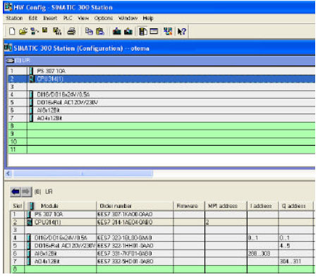 | |
| Fig. 8: | Configuration of hardware used in the design home systems |
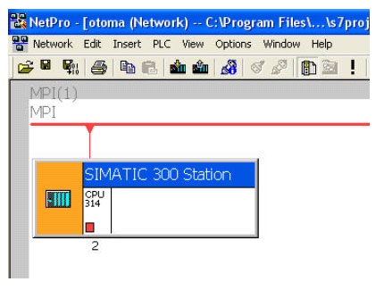 | |
| Fig. 9: | Multipoint interface connection |
 | |
| Fig. 10: | Lader diagram of the PLC for home automation software |
Also, technical specification of hardware used in the designed home system is shown on the interface screen.
Programs are written by the CPU-314 cables installed on Multipoint interface (MPI) (Fig. 9). Written program is loaded to CPU 314 processer using MPI communication cables. As seen on the screen, CPU 314 processer is included in simatic 300 station.
Figure 10 shows a section of designed system programs written in the ladder diagram. Programs are written specifically for each home. Comfort is achieved through special programs required. A part of the written program is given in the ladder diagram of Siemens S7300 PLC.
CONCLUSION
In the study, a home automation was realized by PLC control. PLCs in home automation (power, lighting, water and gas) are firstly used in this field. The design aimed to yield optimum efficiency from energy consumption points such as power and energy systems. The energy of unused areas are cut off by the central control and energy save was achieved with lighting control. The water system in the building was controlled using the valve. In the building, the control of the gas involves turning on-turning off the gas, sensing gas leakage and activating the warning system. The designed system does not require special interfaces in controlling the hardware in the building and it controls the energy systems to the uppermost points. The designed system is economic and easy-to-implement in home automation. In addition, the design offers convenience in maintenance and repair of the system. In the study, it was observed that there is a linear relationship between home automation and energy saving. Lighting control can significantly improve building performance, increase energy efficiency and enhance comfort and satisfaction.
REFERENCES
- Myoung, K.J., J.M. Lee, D.S. Kim and W.H. Kwon, 2006. Home network control protocol for networked home appliances. IEEE Trans. Consumer Electr., 52: 802-810.
CrossRef - Kim, W.S., L.W. Kim, C.E. Lee, K.D. Moon and S.A. Kim, 2002. Control protocol architecture based on lontalk protocol for power line data communications. Proc. ICCE, 1: 310-311.
CrossRef - Yılmaz, E.N., 2009. Education set design for smart home applications. Comput. Appl. Eng. Edu.
CrossRefDirect Link - Huang, H.S., J.Y. Yen, S.L. Chen and F.C. Ou, 2004. Development of an intelligent energy management network for building automation. IEEE Trans. Automat. Scı. Eng., 1: 14-25.
CrossRef - Leong, S.S. and C.H. Vun, 1998. Design and implementation of an authentication protocol for home automation systems. IEEE Trans. Consumer Electr., 44: 911-921.
CrossRef - Borodulkin, L., H. Ruser and H.R. Trankler, 2002. 3D virtual smart home user interface. Proceeding of the International Symposium on Virtual and Intelligent Measurement Systems, (VIMS`02). AK, USA., pp: 111-115.
CrossRef - Bhavani, R.G. and M.A. Khan, 2008. Prevalence and penetration of lighting control systems in dubai buildings: A pointer to future measures. J. Applied Sci., 8: 3460-3466.
CrossRefDirect Link - Xiaohu, G. and Z. Guangxi, 2006. Empowering ubiquitous services in next-generation smart homes. Inform. Technol. J., 5: 64-69.
CrossRefDirect Link - Liao, H.C. and C.C. Tu, 2007. A RDF and owl-based temporal context reasoning model for smart home. Inform. Technol. J., 6: 1130-1138.
CrossRefDirect Link
ravi kumar Reply
could you plesae prvide me all the diagrams of this article.
p. jagadeesh reddy Reply
sir,could you please help me for complete my project on plc based home automation ,this is my final year project in b.tech tanking you sir
deepa Reply
can u plz tell me de pin number of PLC nd pin num of sensor used in thz paper?????