
I. Hassanzadeh
Research Laboratory of Robotics, Department of Control Engineering, Faculty of Electrical and Computer Engineering, University of Tabriz, Tabriz, Iran
H. Jabbari Asl
Research Laboratory of Robotics, Department of Control Engineering, Faculty of Electrical and Computer Engineering, University of Tabriz, Tabriz, Iran
Journal of Applied Sciences
Year: 2009 | Volume: 9 | Issue: 2 | Page No.: 278-286


ABSTRACT
In this study, a new architecture for tele-visual servoing of a robotic manipulator is presented. An overview of methods employed for controlling robotic manipulators using a camera is illustrated. Image-based and position-based approaches are considered. Matlab®, Simulink® and xPC Target® toolbox are used to design a novel user-friendly toolkit called Tele-Visual Servoing Toolkit (TViST) for tele-visual servoing of robotic manipulators. TViST has hardware in the loop (HIL) property, i.e., simulation and implementation of the system are performed in the same environment. Stability analysis of visual servoing systems in presence of time delay is discussed by Lyapunov theorem. Furthermore, effects of robot dynamic on performance of the system are evaluated. In terms of low level control, proportional and H-infinity controllers are implemented as well. As a case study, a 5DOF Gryphon manipulator is considered. Simulations for various mentioned matters are done to validate the theoretical issues. Experimental results for the manipulator employing a virtual camera and a real camera are presented to illustrate and verified the practical performance.
PDF Abstract XML References Citation
How to cite this article
I. Hassanzadeh and H. Jabbari Asl, 2009. Tele-Visual Servoing of Robotic Mamipulators; Design, Implementation and Technical Issues. Journal of Applied Sciences, 9: 278-286.
DOI: 10.3923/jas.2009.278.286
URL: https://scialert.net/abstract/?doi=jas.2009.278.286
DOI: 10.3923/jas.2009.278.286
URL: https://scialert.net/abstract/?doi=jas.2009.278.286
INTRODUCTION
Robotic systems use sensors to identify their environment for manipulation tasks. Sensor integration is a key element in today’s flexible manufacturing workcells to increase versatility and application domain of robots. In industrial tasks, work environment of robots should be changed to adapt capabilities of robots. Besides, it is necessary to teach spatial coordinates of workspace to robots which is done by kinematics equations. Generally, achieving desirably accurate kinematics equations of robots is a time consuming effort. Moreover, frequent calibration of robots is also necessary hence mechanical effects changes precise values of joint variables.
To overcome mentioned problems, vision sensor is introduced as a useful element since it enables robots for noncontact measurement of unstructured environments and can be used to close the feedback loop around the robot pose rather than robot’s joint angles. Applying vision sensor to control the robots called visual servoing in literature.
Classical approaches of visual servoing systems include Image Based Visual Servoing (IBVS) and Position Based Visual Servoing (PBVS) which is considered in this study. The advantages of both PBVS and IBVS are combined in recent hybrid approaches of visual servoing. Among hybrid approaches, 2-1/2-D (Malis et al., 1999) visual servoing is well-established from analytical point of view.
In addition, improving performance of commercial robotic systems, in order to work in situations defined by customers, such as visual servoing of robot, impedance control and any intelligent control of system, needs great skill in low-level programming languages. In order to solve this problem, robotic researchers decided to develop software platforms utilizing high-level robot control programming languages such as C/C++ and programming robotic libraries beside advantages of graphical environment of these languages (RCCL (Loyd et al., 1988) and ARCL (Roberts et al., 1999)). These robotic libraries avoid users from hard-task developing of the custom software platforms. However, because of the complexity of these platforms, it is difficult to modify them and it needs to change the source code. Matlab® which allows taking advantage of the graphical programming facilities of Simulink® is one of the popular software to overcome this problem.
Real-time implementation of image processing algorithms has fundamental role in the performance of the visual servoing systems since vision sensor closes the major control loop in such systems. So, higher speed image processing leads to higher system performance. Nowadays, by increasing processing power of computers, high rate image processing is possible without need to special ad hoc hardware. However, since high rate image processing improves system performance and new complicated image processing algorithms, emerged in industrial application, require more processing time, decreasing processing time is still a problem in this field. Common programming languages which are used for image processing are C and C++. Xvision (Hager, 1998) and ViSP (Marchand, 1999) are good examples of such programming platforms for visual servoing purposes. A visual servoing toolbox for Matlab®/Simulink® is also designed which is only constrained in simulation.
Since, execution time of a Matlab® program comparing with a similar program written in other languages (such as C and C++) takes more, it is not suitable for visual servoing tasks. But, simple programming, user friendly environment and versatile toolboxes are the great advantages of Matlab® which motivated us to design a new image processing toolkit for visual servoing tasks using Video and Image Processing Blockset and user-defined S-functions called TViST. TViST has HIL property.
Furthermore, stability analysis of visual servoing systems in presence of time delay is discussed by Lyapunov theorem. In addition, effects of robot dynamic on performance of the system are investigated. In terms of low level control, proportional and H-infinity controllers are implemented as well. As a case study, a 5DOF Gryphon manipulator is considered. An extensive simulations and experiments (using virtual and real camera) are performed for support the theoretical and practical issues.
MATERIALS AND METHODS
Review of visual servoing: Traditional approaches of controlling manipulators through visual sensor use open-loop architecture. These methods are suitable for pick and place operations, where robot has to manipulate moving objects on a conveyor belt. However, the accuracy of such approaches depends on accuracy of visual data and kinematics equation of robot. Figure 1 shows block diagram of such systems.
Closed-loop structure of visual servoing resolves the mentioned problems and uses advantages of negative feedback properties. Sanderson et al. (1987) categorized the closed-loop visual servoing systems as dynamic look and move visual servoing and direct visual servoing. Both methods consists two major approaches called, Image-Based Visual Servoing (IBVS) and Position-Based Visual Servoing (PBVS). If in the control architecture, inner loop as an independent joint controller is used, it is called dynamic look and move and if, inner loop is omitted and visual data are directly used to control the robot joints, it is indicated as direct visual servoing. For some reasons (Hutchinson et al., 1996), most of the reported visual servoing systems use dynamic look and move structure.
Basically, there are two camera configurations. Camera fixed in the work space, called fixed-camera and camera attached to robot end-effector, called eye-in-hand.
PBVS: In PBVS method (Hutchinson et al., 1996), visual features are extracted to construct 3D information of the workspace (object). This is why this approach is also called 3D visual servoing. Construction of 3D information from 2D image for visual servoing is called pose-estimation in literature. It is difficult and almost impossible to construct exact 3D model of the scene of image. Therefore, suitable estimation approaches are utilized for this task. Estimation of 3D model from image sequences is one of approaches (Hung and Ho, 1999). But in most cases model-based estimation approaches are employed (Oberkampf et al., 1993). Estimated position of object related to camera (end-effector, in eye-in-hand fashion), ![]() , are compared with desired position of robot end-effector, Wref, to produce an error signal in 3D space (Cartesian space), Werror.
, are compared with desired position of robot end-effector, Wref, to produce an error signal in 3D space (Cartesian space), Werror.
(1) |
Simply, a proportional control law can be used to eliminate the error.
 | |
| Fig. 1: | Block diagram of open-loop visual servoing/td> |
 | |
 | |
| Fig. 2: | Block diagram of (a) PBVS and (b) IBVS |
(2) |
where, k is proportional feedback gain and u is the camera velocity in Cartesian space, which is sent to robot joint level position/velocity controller. Figure 2a shows the block diagram of PBVS.
IBVS: In IBVS, there is no need for 3D reconstruction of image. So, this method is also called 2D visual servoing. This technique utilizes the relation between visual features variation and the camera displacement which relates through interaction matrix. For eye-in-hand case and a stationary object, relation is as follows (Spong et al., 2005).
(3) |
where, ![]() is visual features variation, ξ is camera velocity and L(s, q) is interaction matrix (and also called image Jacobean). Interaction matrix depends on visual features, s and robot configuration, q, (Spong et al., 2005). In the simplest case, visual features are image coordinates of points. In this situation, interaction matrix is as follows:
is visual features variation, ξ is camera velocity and L(s, q) is interaction matrix (and also called image Jacobean). Interaction matrix depends on visual features, s and robot configuration, q, (Spong et al., 2005). In the simplest case, visual features are image coordinates of points. In this situation, interaction matrix is as follows:
 | (4) |
where, (u, v) is image coordinates of a point, λ is focal length of camera and z is depth of the point from camera. In order to recognize motion of robot by looking to the image features, it is necessary to extract at least three points from image (Spong et al., 2005). In practice, usually more than three points are used for IBVS. The interaction matrix for n points is:
(5) |
where, Li is interaction matrix for point i, is obtained from Eq. 4.
In IBVS we have an error defined according to image plane,
e (t) = s (t)–sd | (6) |
where, sd is desired image feature (image coordinates of the point in previous example) and s(t) is current image features. The objective is to decrease the error by commanding the robot in correct direction. So, a mapping from image plane error to robot motion direction is necessary. Then, joint-level controller is used to track the generated trajectory. This robot motion control can be made both in position and velocity form. But, it is common to use velocity for joint-level controller. As a simple control scheme, it is desirable to exponentially reduce the error. In this way, a controller should design so that,
(7) |
Regarding to Eq. 3 and 6 we have:
(8) |
Substituting this into Eq. 7 yields,
(9) |
then, the robot joint speed can be obtained using robot’s Jacobean equations:
(10) |
Applying this speed as input to the robot and considering the robot as a kinematic positioning device, the system will be exponentially stable. However, since the robot dynamic is not negligible, actual manner of system will be a little different from desired one (exponentially decreasing of error). ![]() in Eq. 9 is pseudo inverse of L, when L is not square.
in Eq. 9 is pseudo inverse of L, when L is not square.
Figure 2b shows block diagram of IBVS.
 | |
| Fig. 3: | Proposed architecture for tele-visual servoing |
Tele-visual servoing: In order to add the tele-operation capability for the visual servoing in present practical system, a new tele-visual servoing architecture using Matlab® software is used.
Open architecture of Gryphon robot: The Gryphon Robot forms part of a family of robots designed by the Walli group of robots, which are products of Italtec Company, Italy. This manipulator has five revolute joints which are driven by stepper motors. Original control system of Gryphon consists of a CNC processor and three slave processors controlled by WALLI software.
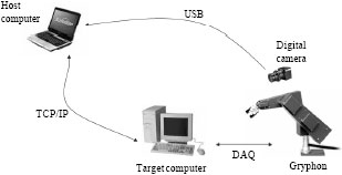
In present study, old control modules of Gryphon manipulator replaced by PC-based control system using Simulink® environment of Matlab®. A host computer (control computer), includes Matlab® control programming and a target computer are connected via TCP/IP protocol using xPC Target® toolbox, conveying advantage of Internet-based control. A vision sensor is also used to implement the visual servoing approaches.
Hardware of system consists of a master (host) computer, a slave (target) computer, the Gryphon manipulator, a digital camera and DAQ cards interfacing the target computer to the Gryphon. Proposed structure shown in Fig. 3.
User-friendly Simulink® toolkit: Simulink® environment of Matlab® is chosen as programming software, to use its advantages in graphical programming and pre-designed Blocksets for the purposes. xPC Target® Toolbox is employed for the tele-operation task. Furthermore, Video and Image Processing Blockset, Image Acquisition Toolbox along with user defined S-functions, are engaged for visual servoing task.
Software architecture consists of two Simulink® models, one for image processing and the other for control of manipulator. All of the control modes can be managed through one GUI model. The Control model operates in real-time mode using Real-Time facility of Simulink®.
 | |
| Fig. 4: | Designed image processing blocks |
For simplicity, in order to validate theoretical aspects of visual servoing systems in Matlab® platform, fiducial markers are considered as visual features. So, binary image processing can be applied for these features, hence needs less processing computations.
Image plane coordinates of points, visual tracking of binary features, pose estimation, selecting and tracking of visual features in area-based mode are designed S-functions to create a simple image processing toolkit for visual servoing tasks beside image acquisition toolbox and video and image processing blockset. Figure 4 shows present designed blocks for image processing tasks consisting TViST.
Image processing model extracts visual features (which are image plane coordinates of points) and tracks them in image sequences. This model acquire images up to 30 fps video rate, so maximum sampling time is 1/30 sec, i.e., the image processing doesn’t work in real-time mode unlike the control model. Output of image processing model sent to the control model via related blocks in xPC Target® toolbox.
A simple approach for pose estimation: Acquiring 3D information for PBVS method needs complicated computational approaches which yield an estimation of the actual pose. Prediction approaches such as Kalman filter methods (Hung and Ho, 1999) uses for this purpose. On the other hand, these approaches are sensitive to initial values of 3D information and fail with far initial values from actual ones.
Among 3D information, computing of features’ (object) depth is much more critical in pose estimation problem. However, for planar objects, there is a simple approach to obtain depth of the object. It is sufficient to know camera’s intrinsic parameters and a model of object along with perspective projection equations of a pinhole camera model.
 | |
| Fig. 5: | Pinhole camera model |
For example in Fig. 5, if distance of points as a model of object (D) is known, then, depth of object (z) can be obtained by using image measurement (d) and camera focal length (λ),
(11) |
Stability analysis: Stability analysis of visual servoing systems is considered in studies (Spong et al., 2005; Chaumette and Hutchison, 2006).
As it is denoted, the visual servoing system has two control loops. One for robot dynamic (inner loop) which operates in high sampling rate and one for visual feedback (outer loop) where has low sampling rate. For example in present practical system, the inner loop has sampling time of 0.0003 sec where outer loop has maximum sampling time of 1/30 sec (Fig. 6). Low sampling rate for outer loop leads to low bandwidth of visual servoing systems due to time consuming operations such as, image acquisition, image processing (main reason) and data transition.
Since in present software structure, visual stages are completely separated from robot dynamic control, time delay in outer loop does not affect the stability of position/velocity control of the robot. So, we do not encounter with the problems mentioned by Zhang et al. (2003). However, time delay may leads to instability of whole system. Since the image processing tasks are done in windows based platform, it suffers from non-real-time inheritance of such an OS. Consequently this increases the time delay for outer loop, in practice and we have variable sampling rate for visual feedback.
Theoretically demonstrating the global stability of a PBVS seems to be out of reach since, variation of the estimated pose as function of a variation of the visual features, is unknown (Marey and Chaumette, 2008).
 | |
| Fig. 6: | Different sampling time for outer in inner loop |
Accordingly we deliberate on analysis of IBVS systems. We can use Lyapunov theory to study the stability of visual servoing systems (Spong et al., 2005). For the system given by Eq. 3 and error defined by Eq. 6, we can use the following Lyapunov function (Spong et al., 2005):
(12) |
Then:
(13) |
Substituting Eq. 8 and 9 in Eq. 13, we have:
(14) |
In order to ensure asymptotic stability of the closed-loop system, we need:
(15) |
Considering λ>0, ![]() should be positive definite. Effect of possible situations for
should be positive definite. Effect of possible situations for ![]() is described by Marey and Chaumette (2008). But for the tele-visual servoing system, we have:
is described by Marey and Chaumette (2008). But for the tele-visual servoing system, we have:
(16) |
where, τ is the time delay. If we assume ![]() is positive definite, then, it is necessary the following condition is satisfied:
is positive definite, then, it is necessary the following condition is satisfied:
(17) |
Considering
(18) |
and substituting in Eq. 17, we should have:
(19) |
 | |
| Fig. 7: | System stability analysis in presence of time delay (a) Time delay is 250*Ts, and (b) Time delay is 255*Ts |
 | |
| Fig. 8: | Pixel error in IBVS with 0.5 sec time delay, (a) Proportional controller and (b) H-infinity controller |
It is impossible to define an upper limit for time delay which causes system to be unstable. In other words, a constant value of delay can make the system unstable, where other values (higher or lower) would not change system stability. For example, Fig. 7 illustrates simulation results of IBVS method for a system with two different constant time delay. In Fig. 7a, time delay is 250*Ts (where, Ts is sampling time of the control model) and the system is unstable. But, in Fig. 7b time delay is 255*Ts (more than previous value) and the system is stable.
In presence of time delay, it makes sense that a high speed controller for robot dynamic is needed. In other words, the more the time delay, the higher speed controller we require. For example, Fig. 8 shows simulation results of an IBVS system for a positioning task (robot has to reach a stationary object), where there is a constant time delay in system. In Fig. 8a, a simple proportional controller used in inner (robot dynamic) loop and Fig. 8b shows results for a high speed robust H-infinity controller. It is clear that in the case of proportional controller the system is bouncing where in H-infinity controller the system is stable.
Figure 9 shows the results for a system with higher time delay (2 sec), controlled with proportional (Fig. 9a) and H-infinity controller (Fig. 9b). In this example, system is stable when a high speed controller is used.
Local minima in degenerated manipulators: In IBVS, there is a potential problem in stability of system when interaction matrix (or ![]() ) is not full rank. In this case, it is possible to reach local minima (Marey and Chaumette, 2008). By definition, local minima is defined such that ξ = 0 (the input to robot dynamic controller is zero) where, s(t)–sd ≠ 0. This problem occurs when s(t)–sd is in null space of
) is not full rank. In this case, it is possible to reach local minima (Marey and Chaumette, 2008). By definition, local minima is defined such that ξ = 0 (the input to robot dynamic controller is zero) where, s(t)–sd ≠ 0. This problem occurs when s(t)–sd is in null space of ![]() . However, there is another local minima type in degenerated manipulators, while camera velocity in Cartesian space has to transform to robot joint space (Eq. 10).
. However, there is another local minima type in degenerated manipulators, while camera velocity in Cartesian space has to transform to robot joint space (Eq. 10).
 | |
| Fig. 9: | Pixel error in IBVS with 2 sec time delay, (a) Proportional controller and (b) H-infinity controller |
 | |
 | |
| Fig. 10: | (a) Error signals in image plane, (b) Controller output (camera velocity) and (c) controller output (joint velocity) |
If robot is degenerated then J-1 has null space. Therefore, there are some non-zero values of ξ which satisfy,
| J-1ξ = 0 | (20) |
Figure 10 shows simulation results of such local minima for the Gryphon manipulator (a 5DOF robot). The remarkable point is, despite error signals and camera speed inputs aren’t zero, robot joints speed inputs are zero.
Same as former local minima, it is also possible to keep from this problem by defining a suitable interaction matrix (L) (Marey and Chaumette, 2008).
RESULTS AND DISCUSSION
In practice, an object including four distinct points is considered for positioning and tracking tasks of the visual servoing system.
 | |
| Fig. 11: | Image plane error in IBVS applying virtual camera |
 | |
| Fig. 12: | (a) IBVS and (b) PBVS |
In experiments, before using a real camera, in order to test the control strategy, an established pinhole camera model as a virtual camera is used. Parameters (Spong et al., 2005) of the employed digital camera are applied in virtual camera model which are extracted by a camera calibration toolbox. Figure 11 shows result of applying virtual camera in positioning task controlled by IBVS method.
Since, visual tracking (using real camera) runs in low frequency (30 Hz), fast variation in camera traveling, fails the visual tracking. So, in practice a simple proportional controller is utilized for the robot dynamic control. Figure 12 shows experimental results of IBVS and PBVS applying the real camera.
It should be recalled that the employed robot in simulation and experimental tests is a degraded Robot, i.e., the gryphon with 5DOF. The interesting point is the simulation and experimental results are consistent and support the previous literatures for 6DOF robots behavior and performance. Nevertheless, there are local minima for degraded robot in PBVS method which is examined earlier.
CONCLUSION
In this study, the gryphon robot is retrofitted which is suitable for implementation various controller specifically visual servoing and tele-visual servoing. The new real time toolkit called TViST is established based on Simulink®, which is the user friendly, easy to use, possesses HIL property and the flexible package. An extensive overview of visual servoing method is illustrated. Stability analysis of visual servoing systems in presence of time delay is discussed by Lyapunov theorem. Furthermore, effects of a robot dynamic on system performance are evaluated. In terms of low level control, proportional and H-infinity controllers are implemented as well. Different local minima of degenerated robot manipulator (here 5DOF Gryphon robot) are pointed out. Various simulations and experiments-with virtual and real camera-are carried out to support the theoretical issues.
The future challenges includes dealing with delay compensation for tele-visual servoing, theoretical aspects of degenerated robot performance in tele-visual servoing tasks, finding a region of interest for tele-visual sevoing stability as well as enhancement of proposed architecture.
ACKNOWLEDGMENT
This study is part of a research was supported by a grant-in-aid (No. D-27-54, 2007) of research to the first author from research affair of University of Tabriz.
REFERENCES
- Hager, G.D., 1998. X-vision: A portable substrate for real-time vision applications. Int. J. Comput. Vision Image Understand., 69: 23-37.
CrossRefDirect Link - Hung, Y.S. and H.T. Ho, 1999. A kalman filter approach to direct depth estimation incorporating surface structure. IEEE Trans. Pattern Anal. Mach. Intell., 21: 570-575.
CrossRefDirect Link - Hutchinson, S., G.D. Hager and P.I. Corke, 1996. A tutorial on visual servo control. IEEE Trans. Robot. Automat., 12: 651-670.
CrossRefDirect Link - Loyd, J., M. Parker and R. McClain, 1988. Extending the RCCL programming environment to multiple robots and processors. Proceeding of the International Conference Robotics and Automation, April 24-29, 1988, Philadelphia, PA., pp: 465-469.
CrossRefDirect Link - Malis, E., F. Chaumette and S. Boudet, 1999. 2-1/2-D Visual Servoing. IEEE Trans. Robot. Autom., 15: 238-250.
CrossRefDirect Link - Marchand, E., 1999. Visp: A software environment for eye-in-hand visual servoing. Proceedings of the International Conference on Robotics and Automation, ICRA, October 10, 1999, Detroit, Michigan, pp: 3224-3229.
CrossRefDirect Link - Marey, M. and F. Chaumette, 2008. Analysis of classical and new visual servoing control laws. Proceeding of the International Conference of Robotics and Automation, March 19-23, 2008, Pasadena, CA., USA., pp: 3244-3249.
CrossRef - Oberkampf, D., D.F. DeMenthon and L.S. Davis, 1993. Iterative pose estimation using coplanar points. Proceeding of the International Conference of Computer Vision and Pattern Recognition, June 15-17, 1993, New York, USA., pp: 626-627.
CrossRefDirect Link - Roberts, J.M., P.I. Corke, R.J. Kirkham, F. Pennerath and G.J. Winstanley, 1999. A real-time software architecture for robotics and automation. Proceeding of the International Conference of Robotics and Automation, May 10-15, 1999, Detroit, MI, USA., pp: 1158-1163.
CrossRefDirect Link - Sanderson A.C., L.E. Weiss and C.P. Neuman, 1987. Dynamic sensor-based control of robots with visual feedback. IEEE Trans. Robot. Automat. RA, 3: 404-417.
CrossRef - Zhang, J., R. Lumia and J. Wood, 2003. Delay dependent stability limits in high performance real-time visual servoing systems. Proceedings of the International Conference Intelligent Robots and Systems, October 27-31, 2003, Albuquerque, NM., USA., pp: 485-491.
CrossRefDirect Link - Chaumette, F. and S. Hutchinson, 2006. Visual servoing control. I. Basic approaches. IEEE Robot. Autom. Mag., 13: 82-90.
CrossRef