
A. Miskam
Engineering Campus, Collaborative Microelectronic Design Excellence Centre, Universiti Sains Malaysia, 14300 Nibong Tebal, Sri Ampangan, Pulau Pinang, Malaysia
S. Korakkottil
Engineering Campus, Collaborative Microelectronic Design Excellence Centre, Universiti Sains Malaysia, 14300 Nibong Tebal, Sri Ampangan, Pulau Pinang, Malaysia
M. Zaidi
Engineering Campus, Collaborative Microelectronic Design Excellence Centre, Universiti Sains Malaysia, 14300 Nibong Tebal, Sri Ampangan, Pulau Pinang, Malaysia
O. Sidek
Engineering Campus, Collaborative Microelectronic Design Excellence Centre, Universiti Sains Malaysia, 14300 Nibong Tebal, Sri Ampangan, Pulau Pinang, Malaysia
Journal of Applied Sciences
Year: 2009 | Volume: 9 | Issue: 13 | Page No.: 2451-2456


ABSTRACT
This study presents the development of a tilt measurement unit using a commercial microelectromechanical system (MEMS) accelerometer based detection system. The objective of this study was to design, fabricate and test the tilt measurement unit for the purpose of inclination measurement and monitoring. The commercial MEMS accelerometer, ADXL202E, from Analog Device was chosen as a detection sensor because of its high sensitivity (12.5%/g) which allows the user to use a lower speed counter for PWM decoding while maintaining a high resolution. An interface circuit that provided different configurations to the accelerometer performance was built and studied. Experimental tests were carried out to characterize the device with the full measurement range of 360°angle. The output results showed nonlinear relationship in single axis tilting due to the construction of the sensor. Preliminary test proved that the developed measurement device is capable of measuring tilt in a single axis and recommendations for further research are offered.
PDF Abstract XML References Citation
How to cite this article
A. Miskam, S. Korakkottil, M. Zaidi and O. Sidek, 2009. Development of a Tilt Measurement Unit Using Microelectromechanical System Accelerometer. Journal of Applied Sciences, 9: 2451-2456.
DOI: 10.3923/jas.2009.2451.2456
URL: https://scialert.net/abstract/?doi=jas.2009.2451.2456
DOI: 10.3923/jas.2009.2451.2456
URL: https://scialert.net/abstract/?doi=jas.2009.2451.2456
INTRODUCTION
Recently, the demand for sensor technology has increased remarkably in all industrial fields. Sensor technology is closely related to cutting-edge technologies such as the semiconductor technology and thus, the high demand for small and light devices with high performance provides the impetus for conducting studies in order to develop sensors with much better performance. The MEMS field, which has rapidly emerged with the advancements in semiconductor technology, is a field of study for the production of micro-devices such as ultra-small structures, sensors, actuators and systems in which the MEMS technology is applied and this has led to a new revolution in the world sensor market.
Sensors for measuring pressure and acceleration and devices such as the inkjet printer head have been commercialized since the 1970s. Among them, the accelerometer has been one of the most successful commercialized MEMS products for air bag crash-sensing applications. The accelerometer is a sensor which converts acceleration from motion or gravity to an electrical signal. Nowadays, MEMS accelerometers are widely used in automobile, navigation, aerospace and portable microsystems not only because of their low cost, high reliability and sensitivity, but also due to their small size and low power consumption (Li et al., 2008).
MEMS accelerometers use various techniques for measuring forces such as silicon piezoelectric (Qing-Ming et al., 2004), piezoresistive (Dan, 2000), resonant (Sung et al., 2003; Ferrari et al., 2005), silicon capacitive (Chih-Ming et al., 2008; Lee et al., 2005) and convective (Leman et al., 2007; Chaehoi et al., 2006). From among a number of sensing methods, the capacitive sensing technique has become the most attractive recently because it provides high sensitivity, low noise performance, good DC response, low temperature sensitivity, low power dissipation and a simple structure. Due to these advantages, silicon capacitive accelerometers have been applied to numerous applications ranging from low-cost, large-volume automotive accelerometers to high-precision, inertial-grade microgravity devices.
The present and potential future markets of MEMS accelerometers are for modern condition monitoring systems (Alhussein et al., 2008; Jagadeesh et al., 2006). The MEMS accelerometers can be used in a wide variety of low g applications such as tilt and orientation, vibration analysis and motion detection. The term tilt sensor is often used to identify a large variety of devices that measure, indicate, or otherwise provide a signal when tilted from a level position, using gravity as a reference (Marin et al., 2005). Within the sensor industry, tilt sensors generally refer strictly to the sensing element itself.
This study describes the development of a tilt measurement unit using a commercial MEMS accelerometer. Tilt is a static measurement where gravity is the acceleration being measured. To achieve the highest degree resolution of a tilt measurement, a low g, high sensitivity accelerometer is required. The commercial MEMS accelerometer ADXL202E, from Analog Device, was chosen as a detection sensor because of its higher sensitivity (12.5%/g) which allows the user to use a lower speed counter for PWM decoding while maintaining a high resolution. The aim of this study is to design, fabricate and test the tilt measurement unit for the purpose of inclination measurement and monitoring.
THEORETICAL ANALYSIS
Commercial MEMS accelerometer, ADXL202E: The ADXL202E is a low-cost, low-power, complete 2 axis accelerometer with a measurement range of ±2 g. The ADXL202E can measure both dynamic acceleration (e.g., vibration) and static acceleration (e.g., gravity). The outputs are Duty Cycle Modulated (DCM) signals whose duty-cycles (ratio of pulse width to period) are proportional to the acceleration in each of the two sensitive axis (Fig. 1). These outputs may be measured directly with the Universal Frequency-to-Digital Converters (UFDC), requiring no Analog-to-Digital Converter (ADC) or glue logic. The DCM period T2 is adjustable from 0.5 to 10 m sec-1 via a single resistor (RSET) by choosing a value between 100 kΩ and 2 MΩ. As outlined in the data sheet, the nominal duty-cycle output of the ADXL202 is 50% at 0 g and 12.5% duty-cycle change per g. Therefore, to calculate acceleration from the duty-cycle:
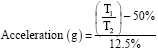 | (1) |
Sensitivity are common physical parameters used to rate an accelerometer. Sensitivity (units: V g-1), is defined as the ratio of a change in the output to a change of the input intended to be measured. According to the manufacturer’s specification sheets, sensitivity can be calculated by:
(2) |
Single axis tilt angle measurement: Figure 2a shows graphical of a device with no tilting. Figure 2b shows the device is being tilted along the x-axis direction. The y-axis remains at 0 g output indicate that this is a single-axis tilting.
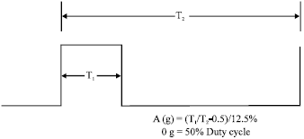 | |
| Fig. 1: | ADXL202E output signal |
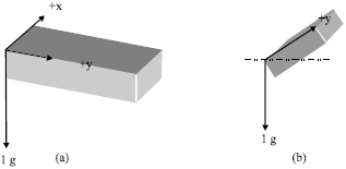 | |
| Fig. 2: | Single-axis tilting |
In order to calculate the tilted angle by the use of accelerometer, the following trigonometry is used:
(3) |
The output acceleration of y axis due to gravity can be defined as the following:
(4) |
Tilted angle is then can be solved by using the following equation:
(5) |
Design and fabrication of Printed Circuit Board (PCB): The study was conducted at the Collaborative Microelectronic Design Excellence Center (CEDEC), Universiti Sains Malaysia, from 1 January 2008 until 31 December 2008. The commercial MEMS accelerometer, ADXL202E, from Analog Device, comes in a surface mount package attached with a Printed Circuit Board (PCB) for easy testing and troubleshooting. Commercial PCB software, DXP2004, was used to design the PCB footprint for the accelerometer, ADXL202E. Figure 3 shows the completed design of footprint with copper pour added to reduce noise and to isolate adjacent signal line. The fabricated artwork completed PCB with mounted ADXL202E is shown in Fig. 4.
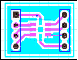 | |
| Fig. 3: | PCB footprint for ADXL202E |
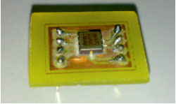 | |
| Fig. 4: | Complete PCB for ADXL202E |
In order to test the accelerometer, it should be interfaced with an external component such as resistor and capacitor. Figure 5 shows the fabricated testing circuit for ADXL202E. There are four different values of the capacitor for XFilt and YFilt. There are also four values for the resistor for Rset. The purpose of putting these different values is to see the changes in performance with different configurations.
EXPERIMENTAL METHOD AND PROCEDURES
The tilt angle measurement setup is shown in Fig. 6. A digital scope was used to observe a duty cycle rather than to analyze a real-time signal, logic and Root Mean Square (RMS) function. The averaging time of a digital scope was increased to reduce the measurement time under semi automation measurements. Therefore, the number of tilt angles presented to the device was squeezed to a minimum. In order to prevent errors and uncertainty in the measurement on output probing, any loose connections or unsuitable cables were avoided. The risk of device oscillation was minimized and measurement time was reduced by directly probing the output of the Device Under Test (DUT).
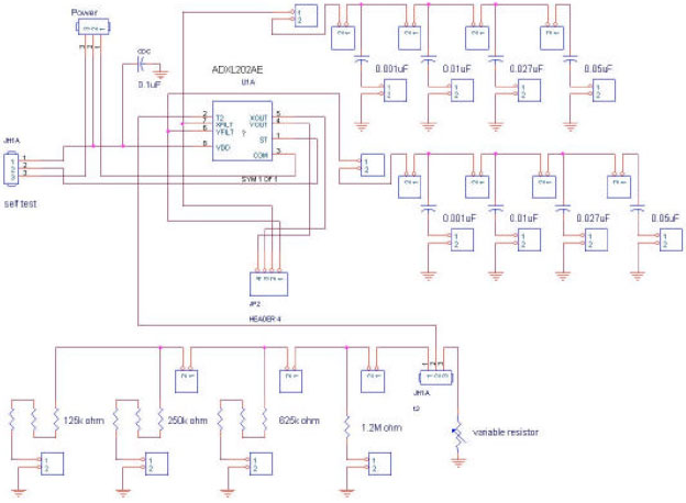 | |
| Fig. 5: | Schematic of a testing circuit for MEMS accelerometer, ADXL202E |
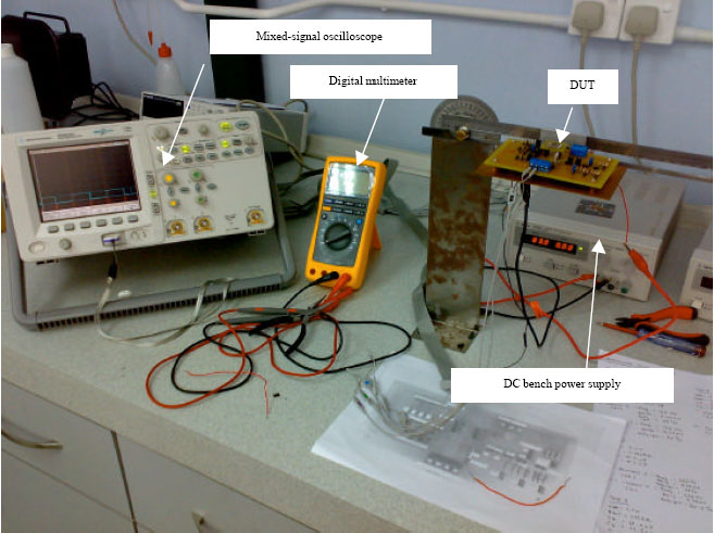 | |
| Fig. 6: | Tilt angle measurement setup |
The system was completed with a 4156C Parameter Analyzer, MSO06102A Mixed-Signal Oscilloscope, E3611A DC Bench Power Supply and a Fluke 187 Digital Multimeter.
The purpose of this test is to measure tilt in a single axis where the accelerometer is mounted perpendicular to gravity and the tilt algorithm is limited to one axis of sensitivity. The test started with DC applied on the device to determine the functionality and to ensure there was no short circuit. At this stage, current compliance needed to be monitored. Analogue voltage and digital output were then measured for a different angle tilt. Measurements were carried out three times for the same parameter to ensure repeatability results. Analogue output and digital output was found to be better in terms of its stability.
RESULTS AND DISCUSSION
The results showed that the device was capable of measuring tilt where the accelerometer output corresponded with the angle changes. The output in voltage nonlinearly changed with the change in the angle (Fig. 7). This is a result of the construction of the sensor. The sensor is a surface micromachined polysilicon structure built on top of the silicon wafer. Polysilicon springs suspend the structure over the surface of the wafer and provide a resistance against acceleration forces. Deflection of the structure is measured using a differential capacitor that consists of independent fixed plates and central plates attached to the moving mass. The fixed plates are driven by 180° out of phase square waves. Acceleration will deflect the beam and unbalance the differential capacitor, resulting in an output square wave whose amplitude is proportional to acceleration (Analog Devices, 1999). Therefore, the principle of the sensor gives it a sinusoidal input vs. output relationship (Ang et al., 2004). Dong et al. (2008) used tri-axis low g MEMS-based capacitive accelerometer from STMicroelectronics (LIS3LV02DQ) to develop a low cost motion tracker. The results for accelerometer analysis showed nonlinear relationship output of x-axis accelerometer.
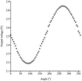 | |
| Fig. 7: | Output in voltage versus angle |
They suggested that, the resolution of the ADC needs to be determined at 0° and 90° to ensure the lowest resolution is still within the requirement. Therefore, due to the nonlinearity of the accelerometer, it is more accurate when the sensing axis is closer to 0° and less sensitive when closer to 90° .
The slope of the curve indicates the sensitivity of the device. The sensitivity decreases with the increase of tilt angle from 0° towards 90° and from 270° towards 360° and increases from 90° towards 270° . Luczak et al. (2006) studied on miniature tilt sensor made of standard MEMS accelerometer, ADXL202E. They observed that, the sensitivity decreases with the increase in roll angle from 0° toward 90° and the sensitivity of accelerometer decreases down to zero for roll angle 90° . Therefore, they proposed that it is more relevant to use a notion of the sensor sensitivity instead of its uncertainty. Owing to application of the proposed method, the inaccuracy of sensor indications decreased from 2° to 0.3° . So, a significant improvement of the sensor performance has been achieved.
CONCLUSION
The design, fabrication and test of a tilt measurement unit using a commercial MEMS accelerometer, ADXL202E, are presented in this study. Preliminary test prove that the developed measurement device is capable of measuring tilt in a single axis where the sensor has several advantages in term of its compact size, low cost and high accuracy in orientation measurement. The output results showed nonlinear relationship in single axis tilting due to the construction of the sensor. The development of a tilt measurement unit will act as the fundamental measurement study for a future self designed MEMS accelerometer.
In the nearby future, we will develop a wireless sensor monitoring system for continuous data monitoring of tilt. The system will be based on wireless RF technology that can measure tilt parameter on-line. This remote continuous data monitoring will be control by computer or receive the report of information by mobile phone. Future studies will also include integrating Programmable System on Chip (PSoC) to improve the measurement data.
ACKNOWLEDGMENTS
The authors would like to express sincere appreciation of the assistance of Mr. Mohd Kusairay Musa and Mr. Faisal Mohamad for his co-operation and assistance in providing support of the software. To Mr. Fazlan, Mr. Sanusi, Mr. Zamri and Puan Rohana, thanks for their kind help. Financial support from the Universiti Sains Malaysia Short Term Grant, 304/PELECT/6035301 is gratefully acknowledged.
NOMENCLAUTURE
| A | : | Output voltage from sensing axis |
| B | : | Output voltage when orientation sense axis at -1 g |
| Vout | : | Output voltage from sensing axis |
| Vzero g | : | Output voltage when sensing axis at 0 g orientation |
| g | : | Gravity acceleration (9.81 m sec-2) |
| S | : | Sensor sensitivity |
| Vout y | : | Output voltage of y axis. |
| Voff | : | Offset voltage |
| θ | : | Angle from x axis |
| ay | : | Acceleration of y axis |
REFERENCES
- Alhussein, A., M. Samir, S. Andrew and P. Robert, 2008. Suitability of MEMS accelerometers for condition monitoring: An experimental study. Sensors, 8: 784-799.
Direct Link - Li, B., W. Zhang, B. Xie, C. Xue and J. Xiong, 2008. Development of a novel GaAs micromachined accelerometer based on resonant tunneling diodes. Sensors Actuators A: Physical, 143: 230-236.
CrossRef - Chaehoi, A., F. Mailly, L. Latorre and P. Nouet, 2006. Experimental and finite-element study of convective accelerometer on CMOS. Sensors Actuators A: Physical, 132: 78-84.
CrossRef - Chih-Ming, S., W. Chuanwei and F. Weileun, 2008. On the sensitivity improvement of CMOS capacitive accelerometer. Sensors Actuators A Physical, 141: 347-352.
CrossRef - Haronian, D., 2000. A low-cost micromechanical accelerometer with integrated solid-state sensor. Sensors Actuators A Physical, 84: 149-155.
CrossRef - Ferrari, V., A. Ghisla, D. Marioli and A. Taroni, 2005. Silicon resonant accelerometer with electronic compensation of input-output cross-talk. Sensors Actuators A: Physical, 123-124: 258-266.
CrossRef - Lee, I., G.H. Yoon, J. Park, S. Seok, K. Chun and K.I. Lee, 2005. Development and analysis of the vertical capacitive accelerometer. Sensors Actuators A: Physical, 119: 8-18.
CrossRef - Jagadeesh, P., M. Umapathy, S.B.M. Arumugam, S. Ramasamy and C.G. Nilesh, 2006. Design of industrial vibration transmitter using MEMS accelerometer. J. Phys: Conf. Ser., 34: 442-447.
Direct Link - Leman, O., A. Chaehoi, F. Mailly, L. Latorre and P. Nouet, 2007. Modeling and system-level simulation of a CMOS convective accelerometer. Solid-State Electronics, 51: 1609-1617.
CrossRef - Qing-Ming, W., Z. Yang, F. Li and P. Smolinski, 2004. Analysis of thin film piezoelectric microaccelerometer using analytical and finite element modeling. Sensors Actuators A: Physical, 113: 1-11.
CrossRef - Sung, S., J.G. Lee and T. Kang, 2003. Development and test of MEMS accelerometer with self-sustatined oscillation loop. Sensors Actuators A: Physical, 109: 1-8.
CrossRef - Ang, W.T., S.Y. Khoo, P.K. Khosla and C.N. Riviere, 2004. Physical model of a MEMS accelerometer for low-g motion tracking applications. Proceedings of the International Conference on Robotics and Automation, April 26-May 1, 2004, New Orleans, LA., USA., pp: 1345-1351.
CrossRefDirect Link - Luczak, S., W. Oleksiuk and M. Bodnicki, 2006. Sensing tilt with MEMS accelerometers. IEEE Sensors J., 6: 1669-1675.
CrossRefDirect Link - Dong, W., K.Y. Lim, Y.K. Goh, K.D. Nguyen, I.M. Chen and S.H. Yeo, 2008. A low-cost motion tracker and its error analysis. Proceedings of the International Conference on Robotics and Automation, May 19-23, 2008, Pasadena, CA., pp: 311-316.
CrossRef