
M. Nizam Ahmad
School of Mechanical Engineering, Universiti Sains Malaysia, 14300 Xibong Tebal, Penang, Malaysia
Solehuddin Shuib
School of Mechanical Engineering, Universiti Sains Malaysia, 14300 Xibong Tebal, Penang, Malaysia
A.Y. Hassan
School of Mechanical Engineering, Universiti Sains Malaysia, 14300 Xibong Tebal, Penang, Malaysia
A.A. Shokri
Department of Orthopedics, School of Medical Sciences, Health Campus,
Universiti Sains Malaysia, 16150 Kubang Kerian, Kelantan, Malaysia
M.I.Z. Ridzwan
School of Mechanical Engineering, Universiti Sains Malaysia, 14300 Xibong Tebal, Penang, Malaysia
M.N.Mohd. Ibrahim
School of Chemical Sciences, Universiti Sains Malaysia, 1 1 800 Penang, Malaysia
Journal of Applied Sciences
Year: 2007 | Volume: 7 | Issue: 3 | Page No.: 349-355


ABSTRACT
In this study, method of multi criteria optimization was used to optimise the size of hip implant to reduce the problem of stress shielding. A computer programme was written by using FORTRAN language to achieve this goal. The optimum implant was modelled and analysed by using I-DEAS software. Results were compared with the reference implant. It was shown that, the optimum implant had reduced the problem of stress shielding at almost 50%. This successful result was encouraged by an optimum load transferred along femur/implant interface.
PDF Abstract XML References Citation
How to cite this article
M. Nizam Ahmad, Solehuddin Shuib, A.Y. Hassan, A.A. Shokri, M.I.Z. Ridzwan and M.N.Mohd. Ibrahim, 2007. Application of Multi Criteria Optimization Method in Implant Design to Reduce Stress Shielding. Journal of Applied Sciences, 7: 349-355.
DOI: 10.3923/jas.2007.349.355
URL: https://scialert.net/abstract/?doi=jas.2007.349.355
DOI: 10.3923/jas.2007.349.355
URL: https://scialert.net/abstract/?doi=jas.2007.349.355
INTRODUCTION
The insertion of an implant into the femur has created a new problem known as stress shielding. Most of the loads which come from patients’ weight and their activities are transferred to the implant (Kuiper, 1993; Paul, 1999). Thus, produce a reduction in stress especially at proximal medial part of the femur. Stress shielding emerges after several years of hip replacement operation. Failure to overcome this problem will create other problems such as bone resorption, loosening and micromotion. These problems provide bad effect to femur and finally the patients may require a revision surgery. The term revision surgery is used when replacing a previously replaced hip joint.
Previous researchers used optimization theory to get the best implant shape and material in reducing the problem of stress shielding (Hedia et al., 1996). Munting and Verhelpen (1995) had proved that bone would receive more load if stem can be eliminated from the prosthesis. Consequently, an artificial femoral head was designed and several screws were used for fixation. Joshi et al. (2000) have extended the work by using a few cables to support the head. Rietbergen and Huiskes (2001) concluded that the proximal load transfer was not improved with the shortened stem. Besides that, it was difficult to position correctly during operation and may possible to lose the initial stability. In other study, Gross and Abel (2001) introduced hollow geometry by increasing stem inner diameter to reduce stress shielding. However, the maximum stem stress has increased dramatically when bending was applied.
Stress shielding can also decreased if stem is more flexible (Bedzinski and Bemakiewiez, 1998; Sumner et al., 1998). However, Huiskes et al. (1992) mentioned that, flexible implant may produce higher stresses along interface. Kuiper (1993) has demonstrated the stress distribution between three different materials, i.e., cobalt chrome, titanium and iso-elastic. From the result, it was verified that iso-elastic of similar stiffness as the bone has created more stress at bone-implant interface at the distal end compared to other materials.
In this study, the optimum size of implant was obtained by using the rule of Multiple Criteria Optimization. ‘Multiple criteria’ is defined that the objective function could be more than one. It was explained through Eq. 1-4.
| (1) |
subjected to
| (2) |
| (3) |
| (4) |
Where F(x) = [f1(x),….., fi(x),….., fm(x)]T was a combination of several objectives.
Surface area at femur/implant interface and implant length were selected as constraints. Area at femur/implant interface should be maximized to permit more load could be transferred to the femur and hence prevented from stress shielding (Hedia et al., 1996). Meanwhile, implant length should be minimized to reduce stress shielding. Shorter stem would allow good load transfer and behave almost like normal situation which was without implant.
MATERIALS AND METHODS
Multi-criteria optimization: Multi-criteria optimization was used to optimise the implant size. FORTRAN was a programming software that has been used in this study. A reference design has been simplified so that it could be translated easily into mathematical equations. Figure 1 depicted the simplified implant.
Optimization parameter, objective functions and constraints must be determined first before running the optimization process.
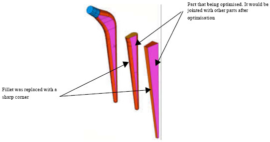 | |
| Fig. 1: | The implant stem has been simplified for optimization purpose |
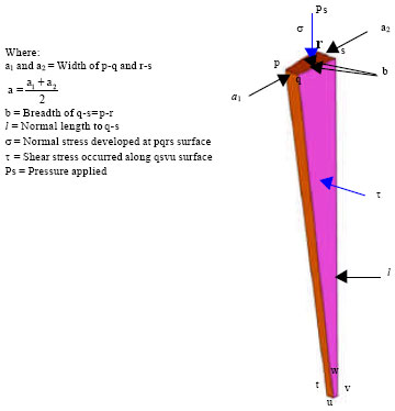 | |
| Fig. 2: | Selected domain with dimensions and applied stresses |
Implant size has been selected as optimization parameter, whereas objective functions were referred to the stresses acted to the implant. Constraints were selected based on optimization parameter.
In order to reduce stress shielding, two objectives have been identified i.e., normal stress, σ (MPa) and shear stress, τ (MPa). Normal stress acting normal to an applied load, whereas shear stress was developed at an interface of femur/implant. Both objectives were directly related to implant outer surface, cross-sectional area and length.
 | (5) |
 | (6) |
Both stresses were combined.
 | (7) |
Constraints depend on femur anatomy and geometry of conventional implant. The values would be manipulated between minimum and maximum limits. Equation 8-11 showed several constraints that were located on implant.
Constraints: | (8) |
| (9) |
| (10) |
| (11) |
A computer programming was developed to optimise the objective function or minimized stress shielding subjected to several of constraints (Fig. 2). The optimization parameter i.e., implant size would undergo for several of iterations until the final optimum parameter is obtained. Figure 3 showed a flowchart on how the programmed was made.
Finite element analysis: Method of Finite Element Analysis (FEA) was applied to validate the optimum implant.
 | |
| Fig. 3: | Flowchart for optimization parameter |
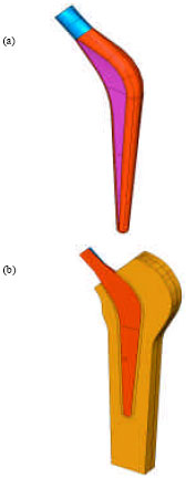 | |
| Fig. 4: | Model of (a) optimum implant and (b) implanted femur |
| Table 1: | Mechanical properties used for finite element model |
 | |
Model of optimum implant and femur was demonstrated in Figure 4 and analysed by using a commercial finite element software, i.e. I-DEAS. The analyses were made by comparing stress distributions between optimum and reference implants. Optimum implant should have lower stress shielding as compared to the reference implant. Mechanical properties used for finite element analysis was shown in Table 1.
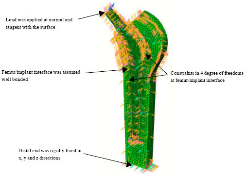 | |
| Fig. 5: | Boundary conditions applied to implanted femur |
Model of implant and femur were divided into small elements type linear tetrahedron. The element length for implant was 1.0 mm. The element lengths given to femur were varied. It was 1.0 mm at femur/implant interface and 2.0 to 3.0 mm as it grew far away from the interface. The load of 3 kN was applied at proximal end of the implant and it was 11° from the vertical axis (Yoon et al., 1989). Symmetrical surface of femur and implant was only permitted displacement in x and y directions. The distal end of femur was rigidly fixed in x, y and z directions, that were Ux = 0, Uy = 0 and Uz = 0. Implant/femur was considered as perfectly bonded. All materials were assumed homogeneous and linearly isotropic. Finite element model for optimum implant inside the femur was shown in Fig. 5.
RESULTS
Figure 6-8 pointed out the comparison of stress shielding occurred when using reference and optimum implant. From the result, it showed that stress had been reduced almost half with the use of optimum implant. The reduction was 42.32% in implant made by Cobalt-Chrome and 43.51% in implant made by Titanium Alloy.
Figure 9 and 10 showed stress distributions developed in femur along symmetrical axis of femur/implant interface. Commonly, femur received less loads when using reference implant. The implant shielded the load from going to the femur. When femur received less loads, it definitely would caused the problem of stress shielding. From Fig. 9 and 10, it was found that the optimum implants have been successfully transferred more load to the femur.
Femur received more stress with the use of optimum implant than reference implant. For optimum Cobalt-Chrome implant, stress developed in femur was increased 42.39% compared to reference implant. For optimum Titanium Alloy implant, stress developed in femur was increased 48.58% compared to its reference.
DISCUSSION
Minimized the stresses: The stresses in both optimum implants were successfully reduced, hence increased their life span. Implant with optimum size increased contact area at femur/implant interfaces as well as encouraged the transfer of the load. Stress was reduced 43.51% with the use of optimum Cobalt-Chrome. The optimum implant made of Titanium Alloy, stress reduction was 42.32%. Figure 6 and 7 showed the comparison between optimum and conventional implants.
Comparison in different implant materials: Titanium alloy and cobalt-chrome: Different implant material would give different value of stresses. It was due to different in mechanical properties.
 | |
| Fig. 6: | Stresses comparison in Titanium Alloy implant |
 | |
| Fig. 7: | Stresses comparison in Cobalt-chrome implant |
Based on the analysis, it was found that the difference in stress distributions occurred in optimum implants made by Titanium Alloy and Cobalt-Chrome was only 0.84%. Figure 8 showed the stresses distributions in both optimum models.
Bones absorbed the stress: Femur needed enough stress to maintain its structure and health. Figure 9 and 10 showed Von Mises stresses that were absorbed by femur. Stress distributions occurred in femur could give a clear picture about the effect of implant to femur. Conventional implant reduced the stress that normally transferred to the femur. This situation might create the problem of stress shielding. However, the use of optimum implant allowed the stress to be absorbed in an optimum manner by femur as well as distributed uniformly to all its surfaces. Femur could absorb more stress from implant if contact area between femur/implant interfaces was maximized. The optimum contact gave more space for the load to be transferred along the interface, hence could minimise the stress shielding problem.
Stable stress distribution: Stress was well and steadily distributed from implant to femur could be seen in Fig. 9 and 10. The failure to distribute the stress either in cemented femur or cement less femur would give a negative effect to femur.
 | |
| Fig. 8: | Stresses comparison in both optimum implants |
 | |
| Fig. 9: | Von Mises stresses occurred in femur for Titanium Alloy implant |
Minor failure of femur would begin until it finally become more serious if not being treated immediately. The understanding on how stress being distributed throughout the implanted femur would allow to a good design of an implant.
Contact area between femur/implant interfaces needed to be maximized to increase a perfection of load distribution. Implant was considered as perfectly bonded to the femur, hence permitted stress to move directly to femur. For the case of cemented femur, cement would act as a medium of transferring stress to the femur (Kuiper, 1993). If stress was transferred well, it would reduce the risk of femur failure such as crack, loosening and micromotion. Bone needed adequate stress to maintain its characteristics.
 | |
| Fig. 10: | Von Mises stresses occurred in femur for Cobalt-Chrome implant |
CONCLUSION
Method of multi criteria optimization has been applied effectively in this study. It produced an optimum hip implant that met all required criteria. The optimum implant was analysed and compared with reference implant. From stress analysis, it was found that the optimum implant could reduce the stress shielding at almost 50%. This reduction was due to larger contact area at interface and shorter of implant length.
REFERENCES
- Gross, S. and E.W. Abel, 2001. A finite element analysis of hollow stemmed hip prostheses as a means of reducing stress shielding of the femur. J. Biomech., 34: 995-1003.
Direct Link - Hedia, H.S., D.C. Barton, J. Fisher and T.T. Elmidany, 1996. A method for shape optimization of a hip prosthesis to maximize the fatigue life of the cement. Med. Eng. Phys., 18: 647-654.
Direct Link - Huiskes, H.W.J., H. Weinans and B. van Rietbergen, 1992. The relationship between stress shielding and bone resorption around total hip stems and the effects of flexible materials. Clin. Orthopaedics, 274: 124-134.
Direct Link - Joshi, M.G., S.G. Advani, F. Miller and M.H. Santare, 2000. Analysis of a femoral hip prosthesis designed to reduce stress shielding. J. Biomech., 33: 1655-1662.
Direct Link - Paul, J.P., 1999. Strength requirements for internal and external prostheses. J. Biomechanics, 32: 381-393.
Direct Link - Rietbergen, B.V. and R. Huiskes, 2001. Load transfer and stress shielding of the hydroxyapatite-ABG hip: A study of stem length and proximal fixation. J. Arthroplasty, 16: 55-63.
Direct Link - Sumner, D.R., T.M. Turner, R. Igloria, R.M. Urban and J.O. Galante, 1998. Functional adaptation and ingrowth of bone vary as a function of hip implant stiffness. J. Biomechanics, 31: 909-917.
Direct Link