
S. Abdurrahman CelIk
Department of Machine Education, Faculty of Technical Education,
Suleyman Demirel University, Isparta, Turkey
Journal of Applied Sciences
Year: 2007 | Volume: 7 | Issue: 12 | Page No.: 1608-1613


ABSTRACT
In this study, various EDM parameters (current, pulse on-time, pulse off-time, gap voltage) applied on a work piece made of Powder Metal (PM) methods. The work piece has similar mechanical properties with DIN 1.2379 material. Experiment specimen is hardened up to 60 Rockwell C average. Meanwhile with different electrode materials EDM process has been applied on the hardened material. Surface roughness Ra (μm) on specimens with different parameters and electrodes is measured. Then, surface roughness values are compared with the values in literature.
PDF Abstract XML References Citation
How to cite this article
S. Abdurrahman CelIk, 2007. Surface Roughness Investigation in the Electrical Discharge Machining of Powder Metal Material. Journal of Applied Sciences, 7: 1608-1613.
DOI: 10.3923/jas.2007.1608.1613
URL: https://scialert.net/abstract/?doi=jas.2007.1608.1613
DOI: 10.3923/jas.2007.1608.1613
URL: https://scialert.net/abstract/?doi=jas.2007.1608.1613
INTRODUCTION
The foundation of Electrical Discharge Machining based on the discovery of electrical discharge and corrosive effect of spark by English chemist J. Priestly in 1770s. However, the first EDM implementation was realized by Mr. and Mrs. Lazeranko in Moscow Technical Institutes during Second World War (1940), (Puertas et al., 2004). EDM which is one of the methods used in machining industry has become wide spread due to the fact that it doesn’t require cutting tools on metal materials having high conductivity and gives opportunity to low price production.
Electrical Discharge Machining, one of the non-traditional manufacturing methods, has been preferred more currently owing to its capability to perform on complex geometry thinly and accurately regardless of its hardness by means of using cheap electrode materials.
The main and crucial advantage of this process is that performance is independent from the mechanical qualifications of machined materials and doesn’t entail a cutting force. Thus, very hard, brittle materials can be manufactured easily and in a desired forms/shapes (Tsai et al., 2003).
EDM is a manufacturing method which is based on the principle that high frequency electric discharge is applied to conductive materials in a controlled manner and thus small pieces are detached from the materials by having melted and evaporated. In EDM process the study performance is determined by four variables: Material Removal Rate (MRR), Electrode Wear (EW), Surface Roughness (SR) and quality of surface. So far, the studies, have aimed to removal maximum materials in less time through increasing MRR. There are still some difficulties in technology to increase MRR. Therefore, studies go on to improve this ratio (Puertas et al. 2004, Puertas and Luis, 2004, Fuling et al., 2004; Amorim and Weingaertner, 2004; Valentincic and Junker, 2004; Lin et al., 2000; Erden and Kaftanoglu, 1981).
MRR depends on not only the work piece material and electrode qualities but also the parameters applied in EDM and the characteristics dielectric fluid. In EDM applications, it’s a desired situation to erode electrode at a minimum degree which removes material from the work piece by running current through itself. In order to decrease the wear ratio of electrode, there have been several studies that put various additives into dielectric fluid. These studies show that fluid with additives have greater performance than non-additives (Valentincic and Junker, 2004; Luis et al., 2005, Wang et al. 1999). EW/MRR ratio is analyzed with volumetric relative wear (Amorim and Weingaertner, 2004). Another performance indicator of EDM process is the roughness occurred on the surface of work piece. Studies on surface roughness takes one of the greater part in EDM works. Surface roughness both depends on the parameters applied during EDM and the variables such as work piece and quality of electrode material as well (Fuling et al., 2004, Peças and Henriques, 2003; Simao et al., 2003; Chow et al., 2000).
In this study, powder metal (Assab79PM) having same chemical qualities of cold work tool steel, which is particularly used in cutting die manufacturing and hardened at 57-58 RC via vacuuming, is applied to EDM process. Copper is used as an electrode material due to its high conductivity and cheapness.
MATERIALS AND METHODS
One of the important features of EDM method is its implementation independently from mechanical characteristic of machined material. When the voltage is applied to the electrode and work piece, electrons detached from electrode (cathode) runs through the work piece in an accelerated mode. While proceeding, they hit neutral dialectic molecules and detach electrons which speed up the flow of electrons to the anode by similar collisions. This movement of electrons causes a leak current dialectically and evaporates dielectric fluid on that part. In evaporated fluid, current increases rapidly. At the end, between the electrode and work piece, there appear a plasma channel. This channel melts/dissolves crater both from work piece and tool. Following the break down of plasma, the whole evaporation and some of the solution blends with the dielectric fluid. Therefore, a crater comes into being on electrode and work piece. The crater consisting of many plasma channels enables the surface manufactured (Fig. 1).
Surface roughness is an important factor in EDM. To find out the optimum time for EDM surface roughness has to be in an acceptable interval. The parameters that affect surface roughness are current, pulse on-time, pulse off-time and gap voltage. Definitions of basic parameters that have impact on manufacturing process are given below;
| • | Current (A): The value of current applied during pulse on-time for EDM. |
| • | Gap voltage (V): Voltage applied between electrode and work piece during EDM. |
| • | Puls on-time (ton) : Current time applied on electrode during each EDM cycle. Removed material is directly proportional with the quantity of applied energy in pulse on-time. This energy can be controlled by current and pulse on-time. |
| • | Pulse off-time (toff) : It’s the period between two pulses on-time. During this period, melted and solidified materials are put out of the medium. In case the pulse off-time is very short, then the spark will be variable. |
The parameters explained above and used as experiment variables will determine the roughness value occurred on the machined surface.
Ra is taken as the bottom and upper equivalent area between the centre line and traces of surface (Fig. 2). Ra is an international symbol that indicates roughness value. Measure tools use average deviation at roughness center. Ra is the deviation from average profile line by arithmetic average of y. It’s determined as the average length (L) measured consecutively.
In this study, the HommelWerke T500 pocket surf type of surface roughness measurement device is used.
 | |
| Fig. 1: | EDM machining principle |
 | |
| Fig. 2: | Surface roughness profile |
EXPERIMENTAL STUDY
In mold manufacture, the use of powder material has become increasingly widespread. Powder metal material is selected because of its ability to obtain desired mechanical features in mold. In this study, Assob79PM work piece which has the same chemical qualification as AISI D2 cold work tool steel is selected. Heat treatment is applied to the whole material in order to increase its hardness to 57-58 Rc. Electrical Discharge Machining is implemented on the surfaces of work pieces having that much hardness.
On the above-mentioned material, EDM process is carried out by three different electrode materials at a different quantity. As shown in Fig. 1, on copper electrode, 320 experiments are done by using various EDM parameters (Table 1) (Salman, 2005).
The working parameters applied for manufacturing powder metal material which is hardened at a depth of 2 mm by electrical discharge are shown in Fig. 1. The line-up view at the nests of the copper electrodes’ used in the experiments are given in Fig. 3. All the experiments are done by Ajan EDM machine produced by Ajan CNC.
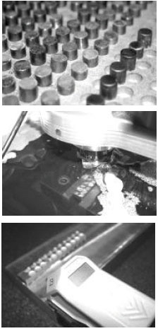 | |
| Fig. 3: | Copper electrodes (ø10x10 mm) and surface roughness measurement device |
| Table 1: | Experimental machining parameters |
 | |
The pieces machined by Electrical Discharge at a depth of 2 mm, is measured through cutting them at any part by HommelWerke T500 surface roughness device. The length of sample (Lc), length of measure (Lm) (5.Lc) and length of travers (Lt) are chosen as 0.25, 1.25 and 1.5 mm, respectively during the measurement (Fig. 3).
RESULTS
As a result of EDM process, experimented by cooper electrode and above mentioned parameters, the measured surface roughness values are given in Table 2.
Besides copper electrodes, copper-tungsten and graphite material are used as an electrode as well and the surface roughness values obtained are indicated in Table 3. Each of the electrodes has good performance qualities depending on various machining conditions.
Figure 4 shows the result of two EDM experiments using different parameters comparatively. One is the result of finish EDM experiment under the condition of 7 Ampere current, 6 μs pulse on-time and 50 μs pulse off-time at various voltages, the other is the result of the experiment under the condition of normal EDM parameters, which are 22 ampere current, 50 μs pulse on-time and 50 μs pulse off-time at various voltages.
The surface roughness values, in a rough Electrical Discharge Machining, under the condition of 42 ampere current, 6 μs pulse on-time and 50 μs pulse off-time at various voltages are illustrated in Fig. 5. Figure 4 and 5 show that increasing the current amount results in increasing the surface roughness.
The results of the experiments done with 7, 12, 22, 42 amperes current, 6 μs pulse on-time and 100 μs pulse off-time at various voltages indicate that the surface roughness augments in case the current and voltage increase (Fig. 6).
It’s found out that the highest roughness values are obtained at 100 μs pulse on-time and 42 ampere current, as shown in the Fig. 7 which is obtained by the variable pulse on-time (6, 12, 25, 50, 100 μs) and current (7, 12, 22, 42 A) values.
| Table 2: | Some values measured during powder metal machining with copper electrode |
 | |
| Table 3: | Surface roughness values measured on powder metal material manufactured by different electrodes |
 | |
 | |
| Fig. 4: | Surface roughness as results of finish and normal EDM |
 | |
| Fig. 5: | Surface roughness results of a rough EDM |
Under the condition of 7 A current, 100 μs pulse on-time and 12 μs pulse off-time, the rougher surface is obtained, however the less rough surface is derived under the condition of 6 μs pulse on-time and 100 μs pulse off-time. Besides, increase in pulse off-time decreases the roughness of the surface (Fig. 8).
 | |
| Fig. 6: | Ra, roughness values, constant variables are ton 6 μs, toff 100 μs |
 | |
| Fig. 7: | Constant parameters are toff 100 μs, gap voltage 60 V |
 | |
| Fig. 8: | Constant parameters are 7A, gap voltage 80 V |
It’s a known fact that not only the comparisons within the study results itself but also the comparisons of the results with that of the studies in the literature which use the similar materials and parameters, shows the success of a study.
Literature studies are summarized systematically with paying attention to machined material similarity, used electrodes and the similarities among EDM parameters in Fig. 4. Analyzed carefully, 1-2, 3-4, 7-8 and 9-10 rows have similar characteristic in terms of machined material, electrodes and EDM parameters.
| Table 4: | The comparison of EDM process with similar studies in the literature |
 | |
When the surface roughness is compared for each of these rows, it’s seen that the powder metal tool machining produces much better results.
CONCLUSIONS
Throughout this study, the surface roughness values of powder metal material as a consequence of EDM process experimented with different electrode materials and machining parameters are investigated. Following conclusions can be derived from this analysis:
| • | As cold work tool steel, powder metal work piece which has chemical characteristic of AISI D2 is used and the results are compared in Table 4. According to results, the lower surface roughness value (Ra) is measured on the powder metal work piece. |
| • | PM workpiece has lower surface roughness on standart tool steel. With an other term, If PM material corresponds required mechanical specifications, PM material could be preferred as the workpiece material. |
| • | For its finer surface finish quality, PM materials could be used where high accuracy needed. |
| • | However, it’s observed that the surface roughness on powder metal material in EDM processes experimented by different electrode materials does not indicate a distinctive feature. |
| • | In Electrical Discharge Machining, it’s not a vital point how hard a material is since materials with high conductivity are used as a cutting tool and machining depends on electron movements. Therefore, EDM can be applied on any materials regardless of it hardness. |
REFERENCES
- Amorim, F.L. and W.L. Weingaertner, 2004. Die-sinking electrical discharge machining of a high-strength copper-based alloy for injection molds. J. Brazilian Soc. Mech. Sci. Eng., 26: 137-144.
Direct Link - Chow, H.M., B.H. Yan, F.Y. Huang and J.C. Hung, 2000. Study of added powder in kerosene for the micro-slit machining of titanium alloy using electro-discharge machining. J. Mater. Proces. Technol., 101: 95-103.
CrossRefDirect Link - Lee, S.H. and X.P. Li, 2001. Study of the effect of machining parametres on the machining characteristics in electrical discharge machining of tungsten carbide. J. Mater. Proces. Technol., 115: 344-358.
Direct Link - Lin, J.L., K.S. Wang, B.H. Yan and Y.S. Tarng, 2000. Optimization of the electrical discharge machining process based on the taguchi method with fuzzy logics. J. Mater. Proces. Technol., 102: 48-55.
Direct Link - Luis, C.J., I. Puertas and G. Villa, 2005. Material removal rate and electrode wear study on the edm of silicon carbide. J. Mat. Proces. Technol., 164-165: 889-896.
CrossRefDirect Link - Pecas, P. and E. Henriques, 2003. Influence of silicon powder-mixed dielectric on conventional electrical discharge machining. Int. J. Mach. Tools Manuf., 43: 1465-1471.
CrossRefDirect Link - Puertas, I., C.J. Luis and L. Alvarez, 2004. Analysis of the influence of edm parameters on surface quality. MRR and EW of WC-Co. J. Mater. Proces. Technol., 153-154: 1026-1032.
CrossRefDirect Link - Puertas, I. and C.J. Luis, 2003. A Study on the machining parameters optimisation of electrical discharge machining. J. Metar. Proces. Technol., 143-144: 521-526.
CrossRef - Simao, J., H.G. Lee, D.K. Aspinwall, R.C. Dewes and E.M. Aspinwall, 2003. Workpiece surface modification using electrical discharge machining. Int. J. Mach. Tools Manufact., 43: 121-128.
Direct Link - Tsai, H.C., B.H. Yan and F.Y. Huang, 2003. EDM performance of Cr/Cu-based composite electrodes. Int. J. Machine Tools Manufact., 42: 245-252.
Direct Link - Valentincic, J. and M. Junkar, 2004. On-Line selection of rough machining parameters. J. Mater. Process. Technol., 149: 256-262.
CrossRefDirect Link