INTRODUCTION
Orthogonal Frequency Division Multiplexing (OFDM) (Li and
Stuber, 2006) is a promising multicarrier digital communication technique
for transmitting high bit-rate data over wireless communication channels. The
indispensable obstacle for most wireless communications systems is the multipath
channel that causes Inter Symbol Interference (ISI). Reliable channel estimation
and tracking is a fundamental step for recovering the transmitted symbols in
the presence of ISI for coherent detection. OFDM systems are also more sensitive
to the frequency offset (Zhang and Lindner, 2005a, b,
2007) which results in the loss of orthogonality among
sub-carriers and causes intercarrier interference (ICI). ICI degrades the performance
of both the channel estimation and symbol detection. So, due consideration should
be given to frequency offset along with ISI. Channel state information can be
obtained in two ways: One way is to insert known symbols (pilots) into the data
on several sub-carriers in frequency and time dimension. This approach is more
feasible even though there is a significant bandwidth loss due to pilot tones.
This has motivated development of blind channel estimation methods which possess
desirable advantages of better bandwidth efficiency. In this approach need for
a pilot sequence is replaced by some knowledge of statistical characteristics
of received signal. However, many blind methods suffer from several drawbacks
which prevent them from widespread use.
Pilot based channel estimation in OFDM is a two-dimensional (2-D) problem which
means channels needs to be estimated in time -frequency domain. Hence, 2-D methods
could be applied to estimate channel from pilots. However, due to computational
complexity of 2-Destimators (Sanzi et al., 2003),
the scope of channel estimators can be limited to one-dimensional (1-D).The
idea behind 1-D channel estimators are usually adopted in OFDM systems to achieve
tradeoff between complexity and accuracy. The focus of this review report is
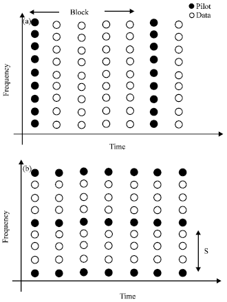
based on 1-D methods. The two basic types of pilot arrangements used in OFDM
1-D channel estimations are block type and comp type in which pilots are inserted
in frequency and time direction respectively as shown in Fig.
1a and b.
Following earlier developments of Blind equalizations algorithms for Single
Input Single Output (SISO) (Shalvi and Weinstein, 1990)
and Single-Input and Multiple Output (SIMO) (Moulines
et al., 1995; Tong et al., 1991) systems,
in recent years, block transmission systems using Linear Redundant Precoders
(LRP) have become popular due to their capability to facilitate block channel
equalization of frequency selective channels. Blind estimation with LRP estimation
with LRP has a small band width expansion factor which is asymptotically unity
and is robust to channel order overestimation.
|
Fig. 1: |
(a) Block-type. (b) Comb-type |
Hence, blind methods developed in LRP systems are considered superior to those
in SIMO systems. As block transmission systems using redundant precoding, such
as Orthogonal Frequency Division Multiplexing (OFDM) systems, become progressively
more popular and research on blind channel estimation is recently given much
attention. Recent developmental work on block transmission systems with redundant
precoding (Pham and Manton, 2003; Su,
2008) has shown that redundancy, originally introduced for purpose of eliminating
interblock interference (IBI), is useful to blind channel estimation. Many blind
methods with different types of redundant precoding have been developed for
block transmission and proved to be free from several limitations present in
conventional blind channel estimation (Moulines et al.,
1995). These new algorithms, however, still have several problems such as
slow convergence speed due to requirement of a large amount of received data
which makes them less applicable in an environment where channel status is fast
varying. Computational complexity, constraints on data constellations are also
some of the problems to be mentioned. Subspace based blind channel estimation
algorithms are widely considered for OFDM systems due to reasons stated by Su,
(2008) and are considered for cyclic prefix (cp)system in this report.
Estimators based on Least Square (LS), Minimum Mean Square Error (MMSE) and Maximum Likelihood (ML) are considered and compared for pilot based and the widely used subspace based algorithm is treated for blind based channel estimation.
Notation: Normal letters represent scalar quantities. Bold symbols denote matrices and vectors. The Discrete Fourier Transform (DFT) matrix of size MxM is given by:
where:
FH denotes The inverse FFT, (.)*, (.)T,
(.)H denote conjugate, transpose and transpose conjugate respectively.
IM denotes identity matrix with M size, U denotes real part,
imaginary part, E{.} is statistical expectation.
OFDM SYSTEM MODEL
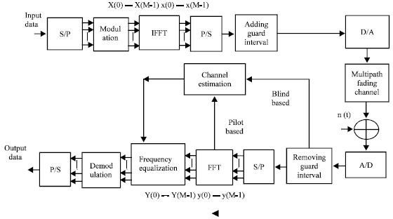
The main idea of Orthogonal Frequency Division Multiplexing (OFDM) transmission is to turn the channel convolutional effect in to multiplicative one. The complete base band OFDM system model is shown in Fig. 2 and described.
Let M be OFDM block length, i be block number and consider the processing of i th block. After serial to parallel conversion the data will be modulated. Then, we take the IFFT of the block as given in Eq. 1. After taking IFFT, a cyclic prefix of length P is inserted to each block. Note that in OFDM systems instead of inserting a cyclic prefix, a set of P zeros can also be added as the guard interval called Zero Padding (ZP).
Suppose x be the M by 1 vector obtained by taking the IFFT of the symbol vector X:
where, F is the MxM FFT matrix xi = [xi(0),
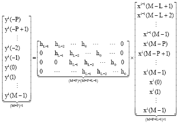
, xi (M-1)]T and let the channel length is L. At receiver if we consider M+P symbols received which are yi (-P), yi (-P+1),
, yi (M-1) we have:
|
Fig. 2: |
OFDM baseband model |
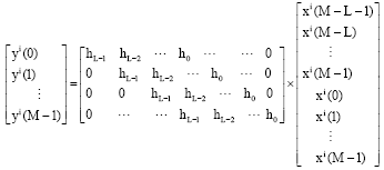
Before any processing, the cyclic prefix of length P is discarded from each block. If P≥L by discarding first P symbols received we get:
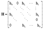
which can be written as:
where, H is an M by M circulant matrix with first column being [ho,
, hL-1, 0,
,0]T Next, we take FFT of received block yi and obtain:
where, Yi = [Yi (0),
, Yi (N-1)]T Since H is circulant, we have:
where, Hk is k th component of M point FFT of the channel:
Due to diagonal structure of H we have:
where, we have included the noise term Nk. Equation 9 demonstrates that an OFDM system is equivalent to a transmission of data over a set of parallel channels.
In regard to channel estimation block, for the pilot based one pilot signals are extracted after the FFT block to compute the channel parameters. For blind estimation information in the CP is processed to compute the channel parameters. After obtaining the channel parameters, phase and amplitude distortion is compensated before demodulation.
PILOT BASED CHANNEL ESTIMATION ALGORITHMS
Pilot based channel estimation is mostly adopted for OFDM communication systems.
Inserting known signal by receiver so that the channel can be estimated at reference value location carries it out. The entire channel can then be estimated. Different channel estimation algorithms are considered for block type and comb type pilot arrangements next.
BLOCK TYPE CHANNEL ESTIMATION
The block type pilot arrangement is shown in Fig. 1a and developed for channel, which is slow fading. Pilot signals are transmitted periodically on all subcarriers. Given pilot signals X and received signals Y, channel frequency response H will be estimated. The estimated channel shall be used to decode received data inside the block till next pilot symbols are received. Appropriate methods will be applied as described below:
LS estimator: relation between transmitted signal Xk and
received signal Yk is already stated in Eq. 9 where
Hk is channel transfer function at kth subcarrier and Nk
is noise for an OFDM system with M carriers, the observations can be computed
as follows:
The least square estimate of such system is obtained by minimizing square distance
between the received signal Y and the transmitted signal X as
(Manolakis et al., 2000). LS estimator minimizes
the parameter:
Differentiating cost function with respect to HH and finding
the minima, we get:
Hence the LS estimate of the channel is:
Without using knowledge of the statistics of the channels, LS estimators can
be computed with very low complexity but it suffers from high mean square error
(Van-de-Beek et al., 1995).
LMMSE estimator: LMMSE estimator utilizes second order statistics of the channel conditions to minimize mean square error. The estimated channel can be computed as:
It is assumed that autocorrelation matrix of the channel Rh
and noise variance
are known in advance by the receiver and can be computed as:
and:
is a rough LS estimate of the channel computed in previous section. Much better
performance can be achieved using LMMSE estimator, especially under low SNR
scenarios (Van-de-Beek et al., 1995). LMMSE estimator
has considerable complexity since a matrix inversion is needed every time data
in X changes. Complexity of this estimator can be reduced by replacing
(XXH)-1 with its expectation E{(XXH)-1}.
Assuming the same signal constellation on all tones and equal probability on
all constellation points, we have:
where, I is the identity matrix. Defining average signal to noise ratio
as:
We get a simplified LMMSE estimator as:
where:
is a constant depending on signal constellation. For instance for 16 QAM transmission
γ = 17/9. Note that X is no longer a factor in the matrix calculation.
Estimator can be further simplified by using low rank approximations (Edfors
et al., 1998; Coleri et al., 2002).
Maximum Likelihood (ML) estimators: ML algorithm regards the channel
as deterministic but unknown vector (Jiang and Weiling,
2003). The ML algorithm achieves Cramer Rao Lower Bound (CRLB) ( Kay,
1993).Therefore, it is a minimum variance unbiased estimator. Minimum mean
square error is achieved on condition the channel state information is considered
deterministic and unbiased. The simple relationship between Y(k) and X(k) for
an OFDM system is:
Channel estimation problem can be solved using the above expression. The channel
frequency response parameters H(0),ÿ,H (M-1) are generally correlated among
each other, whereas impulse response parameters ho,ÿ, hL-1 may
be independently specified, thus number of parameters in time domain is smaller
than that of frequency domain. Hence, it is more suitable to apply ML algorithm
to the above relation to get ML estimate of the channel in time domain. Using
matrix notation, the likelihood function (Chen and Kobayashi,
2002; Jiang and Weiling, 2003) of Y given
X and h is:
where, σ2 is variance of both real and imaginary components of the noise n(k) and is equivalent to:
and the function, usually called the distance function and is defined
as:
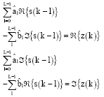
We need to find h that maximize f(Y|X, h), or equivalently, minimize distance function D(h, X). Let hl = al+jbl for 0≤l≤L-1.If we know X, we can solve for hl by:
which will lead to:
For 0≤k≤L-1 or equivalently:
where, z(k) and s(k) are defined as IDFT of Z (k) = X* (k) Y (k) and S (k) = |X (k)|2, 0≤k≤M-1, respectively. If we take DFT of size L on both sides of Eq. 19, we have:
where, superscript (L) denotes size of DFT to distinguish from previous DFT
and IDFT, which are all of size M. Thus
can be obtained as the size L IDFT of Z(L) (l)/S(L) (l)
for, 0≤l≤L-1. That is:
For constant modulus signals, we have |X (k)|2 = C for all k, where C is a constant. Therefore:
In this case, from Eq. 19 we can directly obtain:
Hence, for given X, ML estimate of the channel
is the solution given by Eq. 21 or 23.One
problem with the above algorithm is unknown channel memory length L. However,
since the system requires that channel memory be no greater than guard interval
P we can satisfy this requirement by setting L = P. ML estimator has comparable
performance at intermediate and high signal to noise ratio (SNR) compared to
LMMSE. But at Low SNR LMMSE performs better than ML (Morelli
and Mengali, 2001). ML algorithm is simple for implementation. Note that
large estimation error is inevitable in case of model mismatch.
Estimation with decision feedback: This estimator is proposed to enhance
performance for block type scheme in which estimation is performed once per
block till next pilot symbols are received. The idea here is updating the estimator
inside the block using decision feedback equalizer at each subcarrier (Coleri
et al., 2002). First estimate of the channel
(k=0,
. M-1) in the block can be computed using LS or other methods.
Within the block (Fig. 1a) for each symbol and its subcarriers,
estimation of the transmitted signal is obtained by the previously computed
as:
The estimated transmitted signal
is mapped to binary data through demodulation process in accordance with signal
demapper and then obtained back through signal mapper as
.Then estimated channel
is updated by:
and is used in the next symbol within the block. Application of this scheme is limited to slow fading channels only.
COMB TYPE BASED CHANNEL ESTIMATION
In comb type based channel estimation, pilots are inserted uniformly for each transmitted symbol as shown in Fig. 1b. This arrangement is proposed for intermediate and fast fading channels. Different methods, which are described next section, can be implemented to estimate the channel in frequency domain.
LS estimator based on 1-D interpolation: Equation 9
shows relationship between transmitted signals Xk and received Yk.
T o estimate the channel, pilots symbols are needed. We assume that every p-th
subcarrier contains known pilot symbols (Xpk). Using known pilots
symbols (Xpk) and received symbols (Ypk) at those pilot
sub-carriers, we can calculate raw channel estimate
at pilots as:
where, Npk is the noise contribution at pk -th sub-carrier, Npk
is a scaled noise contribution at that sub-carrier. 1-D linear interpolation
method estimates the channel by interpolating channel transfer function between
and
(fixed time). Where
is raw channel estimate at pk-th subcarrier frequency and time l and
is raw channel estimate at pm-th subcarrier frequency and time l (Coleri
et al., 2002; Hsieh and Wei, 1998). This
estimator works well for a channel with high coherence bandwidth.But fails for
a channel with low coherence bandwidth (Akram, 2007).
It is simple channel estimation. The following interpolation methods can be
employed:
• |
Linear Interpolation (LI) |
• |
Spline Interpolation (SI) |
• |
Cubic Interpolation (CI) |
• |
Low pass Interpolation (LPI) |
The performance of the above interpolation techniques is given in (Arshad
and Sheikh, 2004). Their performance in decreasing order is LPI, CI, SI,
LI.
LS estimator based 1-D general linear models: The channel estimation
problem can also be solved using 1-D generalized linear model framework (Chang
and Su, 2002, 2000; Wang and
Liu, 2002; Tang et al., 2002). The channel
transfer function Hk can be modeled as a linear weighed sum of some
basis function evaluated at k-th sub-carrier frequency as:
Ψi (fk) is i-th basis function evaluated at that k-th subcarrier frequency.
αi is weighing factor of the basis function. M is number of basis functions used in the linear model.
The generalized linear model can be used to rewrite raw channel estimates,
as:
where, every p-th sub-carrier is a pilot, Hpk is actual channel transfer function at pk -th carrier, Npk is noise at pk-th carrier, ψi (fpk) is I-th basis function evaluated at that pk-th sub-carrier frequency fk:
where, Mp is the number of pilot carriers. Using matrix notation, we can write it as:
The least square estimate of weighing matrix is calculated by minimizing the
squared distance between actual channel H and modeled channel
as:
Minimizing we get:
The least-square estimate
can then be used to estimate the channel
at regular sub-carrier frequencies fk as:
Basis functions such as polynomials (Orthogonal or, Legendre polynomials), Fourier series and others can be implemented. For polynomial basis functions, orthogonal polynomials have following merits over legendre polynomials.
• |
The calculation of
remains numerically stable since the product GHG
is a diagonal matrix for orthogonal polynomials |
• |
Since GHG is a diagonal matrix, the
inverse (GHG)-1 can be calculated at
low computational complexity |
• |
The degree of orthogonal polynomials can be increased without
changes in any previous calculation results of  |
This estimator works well as long as the right selection of polynomial order
is done. It is more computational complex as it requires a matrix inversion
and multiplication for each set of pilots. Since same matrix is inverted for
each set of pilot, saving polynomial matrix inverse and using the inverse matrix
for channel estimation for each set of pilots can reduce complexity. It is effective
in reducing LS estimation error (Chang and Su, 2002).
LMMSE estimator based on 1-D winner filtering: Theoretical framework
for 1-D Wiener filtering is presented (Akram, 2007; Scharf,
1991; Edfors et al., 1998; Sandell
and Edfors, 1996). LMMSE method uses knowledge of channel properties to
estimate the unknown channel transfer function at non-pilot sub-carriers. These
properties are assumed to be known at receiver for the estimator to perform
optimally.
Where,
is ith raw channel estimate (at the pilot signal) and ci is ith filter
coefficients. Let us see how to determine filter coefficients. Consider Mp
set of raw channel estimate:
is a raw channel estimate at pk-th subcarrier frequency, Hpk is actual
channel value at pk-th subcarrier frequency and Npk is noise contribution
at pk-th subcarrier frequency.
Given a set of observations on the raw channel estimate
,
LMMSE estimate of the channel can be written
at k-th subcarrier as:
where, ci is i-th Wiener filter coefficient and
is i- th raw channel estimate. The LMMSE HLMMSE, k estimate at k-th
sub-carrier is calculated by filtering raw channel estimate vector
by a Wiener filter cLMMSE = [co c1
cmp-1]T
and can be written as:
where, c and
are column vectors, containing Mp Wiener filter coefficients and
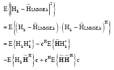
Mp raw channel estimates, respectively. Filter coefficients can be
found by minimizing expected mean square error (Manolakis
et al., 2000). Given as:
Minimizing the above expression we can get:
Let us consider first expression
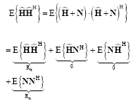
:
The additive white noise (AWGN) and channel are uncorrelated. Hence the above expression can be written as:
where, Rh is autocorrelation matrix of the channel and σ2 is noise-variance per subcarrier. Note that:
Similarly
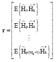
is given as:
where, r is cross-correlation vector of the channel at k th sub-carrier and the channel at pilot locations:
Hence Wiener filter coefficients that provide the LMMSE channel estimate is:
Once we have calculated Wiener filter coefficients, we can estimate channel at k -th subcarrier as:
This estimator outperforms both estimators above especially at high SNR and
low coherence bandwidth. In other words, LMMSE can be applied in sparse multipath
channel (Jiang and Weiling, 2003). But, its performance
will degrade if mismatch between statistical characteristic and real environment
arises. This method is most complex method for channel estimation as it requires
matrix inversion and matrix multiplication for each set of pilots. Moreover,
its high complexity prevent it from widespread application when number of paths
in wireless channel is large (>10).The complexity can be reduced by low rank
approximations (Edfors et al., 1998).
Note that ML estimator can also be applied for comb type pilot estimation (Chen
and Kobayashi, 2002). There are also other channel estimators for OFDM system
such as 2D estimators (Hou et al., 2004), Iterative
channel estimators (Sanzi et al., 2003), estimators
which employ Multiple Antenna (Auer, 2003) and estimators
based on parametric channel modeling (Yang et al.,
2001). Moreover, a channel estimation algorithm which employs wavelet denoising
filters can be applied to obtain more accurate channel estimation by reducing
the effect of the noise on estimated channel (Alnuaimy et
al., 2009).
BLIND CHANNEL ESTIMATION
Finite alphabet and non-finite alphabet based algorithms are two major classifications
of blind channel estimation algorithms in Linear Redundant Precoding (LRP) systems.
Algorithms that employ knowledge of finite alphabet of source data generally
have a shorter convergence time but computationally expenssive when the constellation
size is large (Zhou and Giannakis, 2001; Chotikakamthorn
and Suzuki, 1999). Most non-finite alphabet based algorithms make use of
second order statistics of received data (Heath and Giannakis,
1999; Petropulu et al., 2004). These methods
obviously need a longer convergence time than finite alphabet counterparts before
a true channel estimate can be found due to use of statistics. Another important
category of non-finite alphabet based algorithms uses subspace decomposition
and can also be implemented deterministically (Pham and
Manton, 2003; Cai and Akansu, 2000; Li
and Roy, 2003; Muquet et al., 2002). Subspace
based algorithms are applicable for any kind of constellation, even though they
require a longer convergence time. First subspace based blind channel estimation
algorithm was proposed by Scaglione et al. (1999)
for Zero Padding (ZP) systems. Subspace algorithms in Cyclic Prefix (CP) unlike
in ZP systems the received block contains Inter Block Interference (IBI) which
makes blind algorithms more difficult. These methods all need persistency of
excitation property of the input signal that is signal richness to offer the
data covariance matrix to have full rank. This requirement demands the receiver
to collect number of blocks at least equal to block size for one channel estimate
and hence makes the approach less applicable when the channel is fast varying.
Recently pointed out by Manton and Neumann (2003) that
blind channel estimation without knowledge of finite alphabet in ZP systems
is possible with only two received blocks. An algorithm that views the channel
estimation problem as computing greatest common divisors (GCD) of polynomials
representing received blocks was proposed (Pham and Manton,
2003). Even though many blind algorithms in LRP systems have been developed,
they have limitations such as slow convergence speed, high complexity, poorer
performance as compared to pilot assisted methods.
Subspace based blind channel estimation: Subspace based blind channel
estimation methods for CP systems based on literature (Muquet
et al., 2002; Li and Roy, 2003; Cai
and Akansu, 2000) is discussed below. Let source vector XM
(k) is precoded by MxM constant IDFT matrix
resulted in precoded data. Subscript M shows size of matrix or vectors. A cp
of length L, taking from last L elements of xM (k),
is defined as:
Note that it is assumed L+1<M. The cp is appended to xM (k), forming a vector:
Length of x (k) is D = M+L. The channel is considered to be an FIR filter with a maximum order of L.The channel response h is L+1 column vector [ho h1
hL]T and can be defined as:
The received symbols y (k) are blocked into Dx1 vectors y (k). Let blocked version of the noise is n (k), ycp (k) as first L entries and yM (k) as last Mentries of y (k) so that:
It can be shown that:
where:
In which H is an MxM circulant matrix and nM (k) =
[n (k)]L+1:D is noise vector. The Lx1 vector ycp
(k) contains inter-block interference (IBI) and can be expressed as:
where:
and:
are LxL matrices. ncp (k) = [n (k)]1:L
is the noise component. For channel equalization ycp (k) is
usually dropped and only yM (k) passes to an equalizer T
with dimension of MxM and results in recovered symbol YM (k).When
channel coefficients are identified, optimum value for equalizer T can
be computed to minimize mean square error of equalized symbols.
Let us see now how to estimate the channel blindly: While ycp
(k) is often dropped before equalization, information in ycp
(k) is useful to estimate channel coefficients (Pham and
Manton, 2003; Su and Vaidyanathan, 2007). First
ignore noise term n (k) for simplicity and define a composite block ™
(k) with a length of 2M+L and contains information from two consecutive blocks
as follows:
Then, from Eq. 45 and 46 we have:
where:
and:
Note that
is (2M+L)x2M matrix.
does not have any non zero on unit circle grid
then
has full column rank 2M.
Assume J consecutive received blocks y (0), y (1), ÿ, y
(J-1) are gathered at receiver. Subsequently we shall have J-1 composite blocks
™ (k) defined in Eq. 41 for k = 1,2,
,
j-1. (2M+L)x(J-1) matrix can be constructed by placing these composite blocks
together as:
Note that subscript cobk stands for composite block. Next, we shall have:
where,
is a 2Mx(J-1) matrix. Suppose there exists an integer J≥2M+1 such that
has full row rank 2M. Then rank of
which
means
has L linearly independent left annihilators. Let
be kth annihilator of
, for 1≤k≤L that is
then,
since
has full rank, we can write
as
we can ignore index k in the contents of
for simplicity. By looking at columns of
,
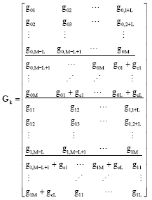
a 2Mx(L+1) matrix Gk can be produced as shown next:
Define
. Then, channel coefficients h can be recovered within a scalar ambiguity
(Cui and Tellambura, 2005) by finding only right annihilating
vector of G. When
has
no full column rank, the above algorithm can be made applicable by making some
modifications (Muquet et al., 2002). In presence
of noise, Eq. 50 can be expressed as:
where, the noise component
comes accordingly from Eq. 45 and 46.
In this case,
often becomes full rank and no longer has L left annihilators. By taking singular
value decomposition(SVD) of
,
the left annihilators
of which is the noise space can be estimated . In the Equation ™ (k):
Un contains singular vectors associated with the smallest
L singular values
of and gk is chosen as kth column of Un.Note
that in Eq. 53 if matrix
is replaced with estimated autocorrelation matrix which is:
Then, null space Un found by singular value decomposition
(SVD) will remain unchanged. Since size of
is usually smaller than
,
especially when J is large, taking SVD on
rather than on
actually saves computational complexity, although an additional computation
will be needed for creating the autocorrelation matrix
.
Once matrix
is created whenever a new block is received, it can be updated easily (Muquet
et al., 2002). The idea of maintaining
can lead to a method in which newer blocks can be weighted more than older ones.
If an initial estimate of
is made first, It can be updated each time a new composite block ™ (k)
is obtained using:
The parameter αε[0,1] is a forgetting factor. The forgetting factor is used especially in time varying channel environments.
A matrix
with 2Mx(J-1) should have full row rank of 2M (property of persistency of excitation)
so that above method work properly. Obviously,
has full row rank only when the number of columns is not smaller than number
of rows, that is J-1≥2M. This requires at least (2M+1).D symbol durations
for the receiver to wait before channel estimation can be performed. This drawback
makes the algorithm not applicable for fast fading channels since the channel
parameters experience change during this time of collecting data. A forgetting
factor can be utilized to give more weight to newer blocks. But use of older
blocks as old as (2M+1) earlier is unavoidable. This fundamental limitation
can be overcome by the method proposed (Su and Vaidyanathan,
2007; Pham and Manton, 2003) for Zero Padding (ZP)
systems.
The other important issue is to deal with the scalar ambiguity in the estimated
channel coefficients (Su, 2008). The frequency response
of the estimated channel is:
due to scalar ambiguity all equalized symbols has to be scaled by unknown complex
valued scalar β. One way of resolving this ambiguity is by introducing
one extra pilot symbol and comparing it with corresponding received symbol.
If several blocks are using same channel estimate
,
the scalar ambiguity can be estimated as follows:
where, C is complex domain, ypil (i) is pilot symbol of the ith block and yrec (i) is the corresponding received pilots. There could be different way of pilot arrangements but attention should be given so that received blocks should not be rank deficient.
DISCUSSION
A review of selected channel estimation algorithms for OFDM communication systems has been presented along with their strength and limitations in this study. Generally, they can be classified as pilot and blind channel estimation algorithms.
Block type pilot channel estimators are suitable for slow fading channels.
The LS algorithm is simple but suffers from high mean square error. The LMMSE
algorithm has superior performance over LS by giving 10-15dB gain in signal
to noise ratio (SNR) for the same mean square error (Van-de-Beek
et al., 1995). However, LMMSE is computationally costly but it can
be simplified by using low rank approximations (Edfors et
al., 1998). ML estimator does not require knowledge of the channel statistics
and therefore it is simpler to implement and has comparable performance at intermediate
and high SNR with that of LMMSE. But at Low SNR LMMSE performs better than ML
(Morelli and Mengali, 2001). Estimation with decision
feedback is proposed to improve the performance of the LS (Coleri
et al., 2002), LMMSE and ML estimator algorithms.
Comb type channel estimators usually out perform for middle and fast fading
channel environments. LS interpolation based estimator is simple and performs
well for a channel with high coherence band width. But its performance is not
good for low coherence bandwidth (Akram, 2007). LS linear
model works well as long as the right polynomial order is selected. The LS model
based is very effective in reducing LS estimation error but computationally
complex. It requires less computation compared to LMMSE winner filtering (Chang
and Su, 2002), since no information about the channel and noise power level
is needed. The LMMSE winner filtering based estimator outperforms both estimators
especially at high SNR and low coherence bandwidth (Akram,
2007). But it is the most complex method. The complexity can be reduced
by deriving an optimal low rank estimator with singular value decomposition
(Hsieh and Wei, 1998).
Subspace based Blind Channel Estimation (BCE) algorithms are widely used for
OFDM system. Generally BCE algorithms are band width efficient compared to pilot
based ones but they suffer from low convergence and high computational cost
which makes them unsuitable for fast fading channel environments at this stage
(Su, 2008).
ACKNOWLEDGMENT
The authors are very grateful to Harbin Engineering University for financing this work.