
Akram M. Zeki
Department of Information System, Kulliyyah of Information and Communication Technology, International Islamic University Malaysia, Malaysia
Azizah A. Manaf
Advanced Informatics School (AIS), University Technology Malaysia, Malaysia
Shayma S. Mahmod
Department of Electrical and Computer Engineering, Kulliyyah of Engineering, International Islamic University Malaysia, Malaysia
Information Technology Journal
Year: 2011 | Volume: 10 | Issue: 7 | Page No.: 1367-1373


ABSTRACT
Watermarking capacity refers to the amount of information we are able to insert into the image. Low signal to noise ratio is a phenomenon of watermarking channels which severely limits the capacity. The aim of this study was to develop a digital watermarking model which can find out the possibility to embed maximum amount of data in an image without degrading the quality of watermarked image. In this approach, the host image will be partitioned into non-overlapping blocks and passing an imaginary plane in the three critical pixels. The characteristics of this plan should not be changed after embedding message; then the same characteristics will be used to evaluate the embedded capacity in the extracting module.
PDF Abstract XML References Citation
Received: February 15, 2011;
Accepted: May 04, 2011;
Published: June 10, 2011
How to cite this article
Akram M. Zeki, Azizah A. Manaf and Shayma S. Mahmod, 2011. High Watermarking Capacity Based on Spatial Domain Technique. Information Technology Journal, 10: 1367-1373.
DOI: 10.3923/itj.2011.1367.1373
URL: https://scialert.net/abstract/?doi=itj.2011.1367.1373
DOI: 10.3923/itj.2011.1367.1373
URL: https://scialert.net/abstract/?doi=itj.2011.1367.1373
INTRODUCTION
Watermarking is a method of embedding information into digital data, the data into which the watermark is to be embedded is usually referred to as the host data. The information is embedded into the host data by performing alterations to the content of the host data. The embedding is done in such a way that the host and watermark object are indistinguishable (Bender et al., 1996).
The use of cryptography in communications makes it obvious to an intruder that the communication is secret because of the encryption used. The digital watermarking problem however requires that the very existence of communication (i.e., the watermark itself) is kept secret. This can be achieved by embedding the watermark in the media imperceptibly and detecting it when required. Such a digital watermark may carry any information depending on the application (Chen et al., 1999). Using watermarking as a viable form of communication has been propelled largely by the growth of the Internet. The Internet offers an opportunity to exchange large amounts of digital information over great distances. The prevalence of media such as audio, video and images on the Internet provides an ideal channel for watermarking communication.
The human visual system HVS is insensitive to the value change in these areas. Thus, we can use these areas to embed messages. Generally speaking, the more significant bit-plane the noise area appears in, the larger variation of grey values among the neighbouring pixels there will be and then more bits could be used to embed messages. So, the first step is based on the grey value variation of neighbouring pixels to compute the number of embedding bits for each pixel (Jain and Uludag, 2002).
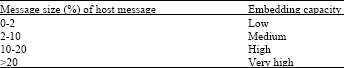
Watermarking capacity refers to the amount of information we are able to insert into the image. Low signal to noise ratio SNR is a phenomenon of watermarking channels which severely limits the capacity. For watermarking image, high embedding capacity may be needed (Zaidan et al., 2010). The challenge is to embed as much information as possible while staying compatible with the image noise model. In general, increasing the capacity will make the watermark more obtrusive in viewing. In addition, the watermarking system is more robust when the watermark signal power rises (Barni et al., 1999). Under the present day scenario a rough estimate of low, medium and high payload, particularly for images, is shown in Table 1.
Although many watermarking techniques have been proposed by various researchers the specific requirements of each watermarking technique vary with the application. Least significant bit LSB technique is one of the earlier techniques of watermarking. Many studies used this technique to develop different watermarking models, recently (Zeki and Manaf, 2009) improved it to new technique called intermediate significant bit ISB. Further improvement has been done to use ISB technique within a block of pixels together (Zeki and Manaf, 2011).
| Table 1: | Payload categorization based on message size (Shelby, 2004) |
 | |
Wu-Tsai’s method (Winkler et al., 2002) inserts the secret data into a grey-valued host images by pixel-value differencing PVD. First, a grey-valued host image is partitioned into non-overlapping blocks of two consecutive pixels, say pi and pi+1. From each block we can obtain a difference value di by subtracting pi+1 from pi. All possible difference absolute values of di range from 0 to 255. if di≈0, we can consider pixels pi and pi+1 locate within the smooth area. Otherwise, if di≈255, di is located on the edged area. Wu-Tsai’s scheme hid more secret data into edged areas than smooth areas, in order to maintain the good quality of the watermarked image (Winkler et al., 2002).
Yeuan and Ling developed new method to improve the capacity of the watermarking embedding (Jain and Uludag, 2002). First, for each pixel, the capacity evaluation component uses the grey-scale variation of neighbouring pixels and its intensity to evaluate its embedding capacity. Notice that the local characteristics should not be changed after embedding message; then the same characteristics can be used to evaluate the embedded capacity in the extracting module. Then, the minimum-error replacement component finds a replacing grey scale.
However, a loophole exists in the PVD method. Unusual steps in the histogram of pixel differences reveal the presence of a secret message. An analyst can even estimate the length of the hidden bits from the histogram. Zhang and Wang (2004) proposed a modified scheme to enhance security and avoid the occurrence of the above-mentioned steps in the pixel difference histogram, while preserving the advantage of the low visual distortion of the PVD. However, using only two blocks to make prediction may result in a highly distorted block, the two-sided, three-sided and four-sided side match methods are employed, as shown in Fig. 2. In another words, this method provides a large embedding capacity with little perceptual distortion (Chang and Tseng, 2004).
Recently many studies tried to improve the capacity of data embedding such as: Hmood et al. (2010), Qi et al. (2010) and Ahmed et al. (2010). The aim of this study is to develop a digital watermarking model which can find out the possibility to embed high amount of data in an image without degrading the quality of watermarked image.
THE PROPOSED METHOD
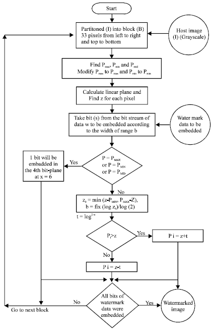
There are two criteria opposing each other: Trying to embed the maximum amount of data and keeping minimum amount of distortion so that the difference in picture with and without watermark data is not detected by naked eyes. In this approach, analysis of the original host image will be made in order to classify the regions of the image. The second step is the selection of the sequence of watermark data which will be chosen to embed data within the original image. The embedding process will use a key for embedding data. The same key will be used for restoring of embedded data. Attempts for increasing the amount of embedded data and then evaluation of quality of picture noise and noise recognition by naked eye has to be made.
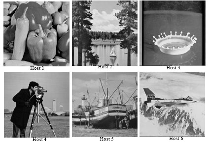
Host image classification: Six host images were used in this study, as shown in Fig. 1. Each host image contains 256x256 pixels. The host images are the standard images for watermarking and they were downloaded from the internet. They can be found in many websites, for example the Greyscale Standard Images (http://www.dip.ee.uct.ac.za/imageproc/stdimages/greyscale/). The names of these host images are Peppers, Lake, Airplane, Milk drop, Camera man and boat, respectively.
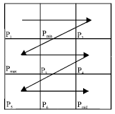
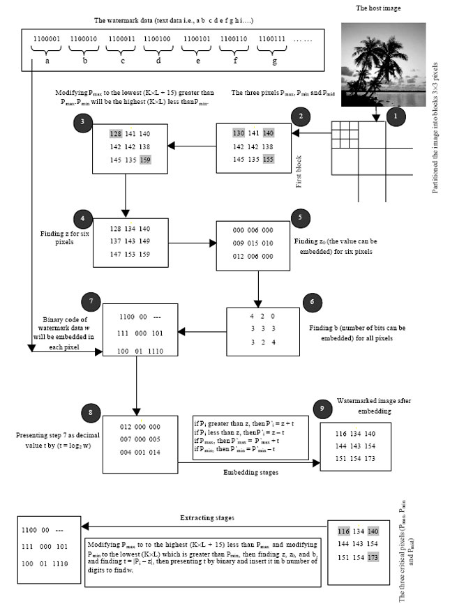
The host images will be partitioned into non-overlapping blocks; each block contains n x m pixels. Consider a block of 3x3. After partitioning the image into blocks and presenting each pixel as decimal (0:255), three pixels from each block will receive special treatment. The first pixel is the maximum pixel value Pmax, the second pixel is the minimum pixel value Pmin and the third pixel Pmid is the furthest point from Pmax and Pmin. The embedding module will be applied to each block from left to right and from top to bottom in the image sequentially and for each block (9 pixels, 3x3), after finding Pmax, Pmin and Pmid. The other 6 pixels P1, P2, …. P6, will be addressed from left to right and from top to bottom in an image sequentially as shown below in Fig. 2.
Figure 2 assumed that Pmax in (2, 1) and Pmin in (1, 2) then Pmid will be in (3, 3). The furthest point Pmid will be found according to the distance from the two pixels (Pmax and Pmin), i.e. if Pmax in (1, 1) and Pmin in (3, 1) then Pmid will be in (2, 3) and so on. Pmid coordinates could be found also by a suitable look up table.
Embedding stages: We consider the watermark text message as a long bit stream after presenting watermark as ASCII code, we want to embed every bit in the bit stream into the blocks of the host image. The number of bits t which can be embedded in each block is decided by the suitability embedding block and from pixel to another pixel. The sequence of watermark data shall be carefully selected and inherited into the key which will be inherited into the program used for recovering the embedded watermark later. The first step for embedding information is modifying the maximum point Pmax to P’max and modifying the Pmin to P’min based on range table which is design by user.
 | |
| Fig. 1: | The greyscale host image, with 256x256 pixels each |
 | |
| Fig. 2: | Addressing the 9 pixels |
Notice that the new P’max and P’min should carry some characteristics which should not be changed after embedding message; then the same characteristics will be used to evaluate the embedded capacity in the extracting module.
The length of the range is L = 2n, n is from 0 to 8 (there are 8 bits per pixel for gray images). In this study n = 4 (up to 4 bits) so L = 16, the number of ranges N = 256/L = 16 ranges. Assume that K is from 0 to N-1, P’max will be the lowest (KxL+15) which is greater than Pmax. While P’min will be the highest (KxL) which is less than Pmin. P’max will be one from this list: [15, 31, 47, 63, 79, 95, 111, 127, 143, 159, 175, 191, 207, 223, 239 and 255]. While P'min will be one from this list: [0, 16, 32, 48, 64, 80, 96, 112, 128, 144, 160, 176, 192, 208, 224 and 240]. Notice that P’max remains the maximum pixel value and P’min remains the minimum pixel value.
The embedding process idea is to pass an imaginary plane in the three pointsPmax, Pmin and Pmid. Then the plane constants A, B and C will be calculated, as shown in Eq. 1. By substituting x and y for each of the remaining 6 points, z for each of them can be calculated where, z is the point on the linear plane:
| (1) |
The idea of using the imaginary plane is to make the watermarked image more close to original image and embedding more data into edge areas because the Human Visual System (HVS) is less sensitive to distortions around edges and in textured areas than in smooth areas. This effect is called spatial masking and can also be exploited for watermarking by increasing the watermark energy locally in these masked image areas because the human eyes cannot detect the noise in these areas (Winkler et al., 2002; Wu, 2001; Wu and Tsai, 2003).
In the next step we will find z0 which is the maximum value that can be embedded in each pixel, z0 is the distance from z to the nearest edge either Pmin or Pmax as shown in Eq. 2:
| (2) |
For each pixel we will find the number of bits, b that can be embedded as shown in Eq. 3. The sequence of watermark data will be divided into groups of size b. Each group w is presented by decimal value t which can be calculated by Eq. 4:
| (3) |
| (4) |
For embedding process, if Pi is grater than z, the P’i will be z + t, while if Pi is smaller than z, P’i will be z-t as shown in Eq. 5. This step is important to decrease the noise or deviation from the original picture values.
 | |
| Fig. 3: | Embedding steps of the proposed method |
| (5) |
Further, embedded data into Pmax and Pmin as described above can be considered b up to 4 bits then t will be found as previously. New P’max and P’min will be calculated as shown in Eq. 6 and 7, respectively. By this step eight pixels from nine have been used for embedding:
| (6) |
| (7) |
Embedding steps can be illustrated in Fig. 3. While Fig. 4 shows detailed example for embedding text into host image by proposed method.
During the extraction stage the three critical pixels (Pmax, Pmin and Pmid) must be found first, then modifying Pmax to the highest (KxL+15) which is less than Pmax and modifying the Pmin to the lowest (KxL) which is grater than Pmin, as in step 2 and 3, then finding z, z0 and b (the number of bits have been embedded), as steps 3, 4 and 5. Finding t by calculating the difference between Pi and z, then presenting t by binary code and insert it in b number of digits to find w and then collecting each 7 bits together and presenting these groups by decimal and then by characters as ASCI code.
 | |
| Fig. 4: | Example for embedding text into host image by proposed method |
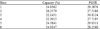
| Table 2: | The Capacity and PSNR values for each image using the proposed method |
 | |
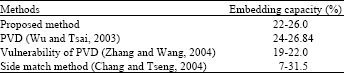
| Table 3: | Comparison between embedding capacities |
 | |
RESULTS AND ANALYSIS
The embedding process has to be applied to all the blocks, i.e., from right to left and from top to bottom. Similarly, a random text message has also been used to embed into the host images. The capacity of embedding = (the number of bytes of watermarked data/number of bytes of the host image)x100% from the host image; the watermarked images after embedding within all blocks of selected host images. Table 2 shows the capacity of the embedded data into all images and the PSNR value for each image.
The above shows that the total capacity is considered very high embedding capacity because the total capacity ranges between 22-26%. The values of the PSNR are almost around 30db range in most cases.
To compare the results of the embedding capacity for the different methods with some other methods, Table 3 shows the comparison table of embedding capacity.
The comparison of the different methods reveals that the proposed method can be considered as one of the highest embedding capacity methods.
CONCLUSION
There are two criteria opposing each other: Trying to embed the maximum amount of data and keeping minimum amount of distortion so that the difference in picture with and without watermark data is not detected by naked eyes. The host image has been partitioned into non overlapping blocks; each block contains 3x3 pixels, for each block three critical pixel (the maximum pixel value Pmax, the minimum pixel value Pmin and the Pmid which is the furthest point from Pmax and Pmin) have been received special treatment, in order to pass an imaginary plane to decrease the noise or deviation from the original picture values. Very high embedding capacity because the total capacity ranges between 22-26%. The values of the PSNR are almost around 30 db range in most cases, because this method embeds more data within edges areas than smooth areas.
REFERENCES
- Bender, W., D. Gruhl, N. Morimoto and A. Lu, 1996. Techniques for data hiding. IBM Syst. J., 35: 313-336.
CrossRefDirect Link - Chen, P.C., Y.S. Chen and W.H. Hsu, 1999. Adaptive-rate image watermarking based on spread spectrum communication technique. Proceedings of the 3rd IMACS/IEEE International Multi-Conference on Circuits, Systems, Communications and Computers, (CSCC`99), Athens, Greece, pp: 1-6.
Direct Link - Jain, A.K. and U. Uludag, 2002. Hiding fingerprint minutiae in images. Proceedings of 3rd Workshop on Automatic Identification Advanced Technologies (AutoID), March 14-15, Tarrytown, New York, USA., pp: 97-102.
Direct Link - Barni, M., F. Bartolini, A. De Rosa and A. Piva, 1999. Capacity of the watermarking channel: How many bits can be hidden within a digital image. Proceedings of the Security and Watermarking of Multimedia Contents, April 9, San Jose, CA., USA., pp: 437-448.
Direct Link - Winkler, S., E.D. Gelasca and T. Ebrahimi, 2002. Perceptual quality assessment for video watermarking. Proceedings of the International Conference on Information Technology: Coding and Computing, April 8-10, Las Vegas, NV., USA., pp: 90-94.
CrossRef - Wu, D.C. and W.H. Tsai, 2003. A steganographic method for images by pixel-value differencing. Pattern Recognit. Lett., 24: 1613-1626.
CrossRefDirect Link - Zeki, A.M. and A.A. Manaf, 2011. ISB watermarking embedding: A block based model. Inform. Technol. J., 10: 841-848.
CrossRefDirect Link - Zaidan, A.A., B.B. Zaidan, A.K. Al-Fraja and H.A. Jalab, 2010. Investigate the capability of applying hidden data in text file: An overview. J. Applied Sci., 10: 1916-1922.
CrossRefDirect Link - Hmood, A.K., H.A. Jalab, Z.M. Kasirun, B.B. Zaidan and A.A. Zaidan, 2010. On the capacity and security of steganography approaches: An overview. J. Applied Sci., 10: 1825-1833.
CrossRefDirect Link - Qi, K., D.F. Zhang and D. Xie, 2010. A high-capacity steganographic scheme for 3D point cloud models. Inform. Technol. J., 9: 412-421.
CrossRefDirect Link - Ahmed, M.A., M.L.M. Kiah, B.B. Zaidan and A.A. Zaidan, 2010. A novel embedding method to increase capacity and robustness of low-bit encoding audio steganography technique using noise gate software logic algorithm. J. Applied Sci., 10: 59-64.
CrossRefDirect Link - Zeki, M.A. and A.A. Manaf, 2009. A novel digital watermarking technique based on ISB (intermediate significant bit). Proceedings of the International Conference on Applied Computing and Engineering Mathematics, Feb. 25-27, Penang, Malaysia, pp: 989-996.
Direct Link - Zhang, X. and S. Wang, 2004. Vulnerability of pixel-value differencing steganography to histogram analysis and modification for enhanced security. Pattern Recognit. Lett., 25: 331-339.
CrossRefDirect Link - Chang, C.C. and H.W. Tseng, 2004. A steganographic method for digital images using side match. Pattern Recognition Lett., 25: 1431-1437.
CrossRefDirect Link