
Birhanu Fufa
Department of Mechanical Design, School of Mechanical and Electrical Engineering, Harbin Institute of Technology No. 92, West Da-Zhi Street, Harbin, Heilongjiang 150001, China
Chen Zhao-Bo
Department of Mechanical Design, School of Mechanical and Electrical Engineering, Harbin Institute of Technology No. 92, West Da-Zhi Street, Harbin, Heilongjiang 150001, China
Ma Wensheng
Department of Mechanical Design, School of Mechanical and Electrical Engineering, Harbin Institute of Technology No. 92, West Da-Zhi Street, Harbin, Heilongjiang 150001, China
Information Technology Journal
Year: 2010 | Volume: 9 | Issue: 3 | Page No.: 600-604


ABSTRACT
This study investigates the complicated interaction between the deployment and locking processes of satellite flexible solar panel with the attitude of the satellite. Flexible panels have low fundamental vibration modes and are more likely to deflect and vibrate due to the inertia and external forces. These modes are often excited during normal on-orbit operations. In this study, the application of ADAMS (Automatic Dynamic Analysis of Mechanical Systems) and ANSYS computer programs to the modeling and simulation of the situation during solar panel deployment and locking operations is presented. The simulation result demonstrates how the deployment and locking operations affect the attitude of the satellite. Designers can use this model to decide as to which part they should give emphasis in the design of vibration control of the flexible solar panels.
PDF Abstract XML References Citation
How to cite this article
Birhanu Fufa, Chen Zhao-Bo and Ma Wensheng, 2010. Modeling and Simulation of Satellite Solar Panel Deployment and Locking. Information Technology Journal, 9: 600-604.
DOI: 10.3923/itj.2010.600.604
URL: https://scialert.net/abstract/?doi=itj.2010.600.604
DOI: 10.3923/itj.2010.600.604
URL: https://scialert.net/abstract/?doi=itj.2010.600.604
INTRODUCTION
Orbiting spacecraft with deployable appendages play an important role in variety of space related researches. In accordance with an increase with in mission demands and capacity of launch vehicles, large, complex and highly flexible spacecraft have emerged in past decades. They usually consist of flexible appendages such as solar panel, antennas, booms, manipulator arms, tethers, etc. attached to the central rigid or flexible body of spacecraft. The deployable solar panels are stowed during launch into a small volume due to space restriction and are then extended on-orbit, so realizing a satellite with a much larger area for mounting of solar arrays. At the end of deployment it undergoes locking at the joints at an intended position in order to perform its mission as the power source of a satellite. This locking operation may lead to impulsive forces and moments on the system. This incurs a large vibration in the lightweight flexible solar panels.
In the early stages of space exploration when spacecraft intended to be small, mechanically simple and essentially inflexible, elastic deformations were relatively insignificant. The study of the effect of flexible appendages elastic deformation on the attitude of spacecraft gets more attention after the US first satellite (Explorer I) faced certain problems in its mission (Efroimsky, 2002). One of those problems was the effect of appendages flexibility on the attitude of the satellite.
So far, various researchers have simulated solar panel deployment and locking operations using various methods. Wallrapp and Wiedemann (2002) simulated three-dimensionally the deployment of a solar array using the multibody program SIMPACK. Kuang et al. (2004) modeled a satellite as a central body with two hinge-connected deployable solar panel arrays and investigated motion of the system both during deployment of the solar panels. Kojimaa et al. (2008) simulated the ADEOS spacecraft attitude response due to the stick-slip effect. Nagaraj et al. (1997) constructed a mathematical model and an experimental rig to study the dynamics of a two link flexible system undergoing locking. Joseph et al. (2008) demonstrated estimation of responses of large flexible panels attached to a free rigid system when subjected to torque. Er-Wei et al. (2008) used the ADAMS software to simulate the deployment and locking operations of honeycomb solar panels. Verheul et al. (2001) simulated Curwin Solar Panel System using ADAMS software. Carpine et al. (2009) performed a correlation between predictions from an ADAMS made simulator as well as JAMES made simulators and real flight measurements on a SOLARBUS solar array. Wallrapp and Wiedemann (2003) created the mode shapes of the flexible solar panel using NASTRAN and FEMBS and made the deployment simulation using SIMPACK.
The deployment of a multi-link beam structure which undergoes locking and the effects of slenderness ratio and shear were investigated by (Na and Kim, 2006).
Balaji et al. (2003) developed interactive software in C++ language using principles of object-oriented programming which provides the description of the deploying array. Seo et al. (2003) proposed modeling using Strain Energy Hinge that has nonlinear buckling properties. Mobrem and Adams (2006) compared ADAMS simulation results to measured flight data taken during the three boom deployments of the MARSIS antenna booms. Narayana et al. (2000) modeled the motion of the satellite with two wings of solar array attached to the two faces of the spacecraft using ADAMS software.
This article presents the modeling, simulation and assessment of deployment and locking operations of satellite flexible solar panel using ANSYS and ADAMS software.
MATERIALS AND METHODS
The satellite is modeled by considering the main body and two yokes, which connect the main body and two adjacent panels as rigid bodies and solar panels, are modeled as flexible bodies. All eight panels have the same geometry. The panels are stowed during launch into a small volume and are then extended on-orbit. At the end of deployment it undergoes locking at the joints. In this study a solar array with two wings has been considered, which is illustrated by Fig. 1a-c. Each wing consists of a yoke and four flexible panels. The solar panels are deployed by the energy provided by preloaded torsion springs mounted at the interpanel hinges. The yoke and the panels are similarly connected with different spring parameters and deployment angles. As the angle between two panels reaches the deployed state the hinge is locked by a locking mechanism.
The finite element modeling of the flexible panel is created using ANSYS and the deployment simulation is made using ADAMS. Thin shell elastic 4 node 181 element type is used for the finite element model of the solar panel in ANSYS. The static and normal mode analysis results of each panel are combined and then it is applied to the flexible body dynamic model of ADAMS and its dynamic and vibration analysis is performed. The deployment simulations were carried out at space without gravity while the satellite is free and can move and rotate. The initial data considered for this simulation are: mass of the center body 680 kg, mass of each solar panel 5 kg, size of each solar panel 1.42x0.76x0.0158 m (LxWxD), material used for the solar panel is aluminum with density of 2.76x10³ N m-3 young’s modulus of 6.8x10¹⁰ N m-2 and poison ratio of 0.33, size of each yoke 1.42x0.36x0.01 m (LxHxD), mass of each yoke 3.3 kg. The simulation is performed with 1.00001 sec end time and 50 steps.
The preload in the deployment springs drives the deployment motion. In this design, the preload decreases linear from 0.39093 N m at the array root hinge line to 0.160 N m at the top hinge line. The torsion stiffness of the root spring is equal to 0.2499 N m rad-1 and for the other springs is equal to 0.0936 N m rad-1 giving a constant torque throughout the full deployment. By varying the preload torque in the first hinge and the other springs, the solar array can be used for both 180° panel-hinge deployment and 90° root-hinge deployment.
RESULTS AND DISCUSSION
The result from the simulation is analyzed in various ways. This simulation work helps in predicting the deployment trajectory to investigate any dangerous situations like collision with other parts of the satellite appendages resulting from the deployment of the panels. The deployment must behave in a smooth manner and all panels must deviate as little as possible from their shortest path from stowed to deployed position. The simulation work also helps in predicting the effect of deployment and locking on the attitude of the satellite.
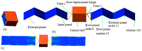 | |
| Fig. 1: | Satellite solar panel deployment: (a) stowed position, (b) during deployment and (c) fully deployed state |
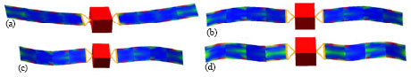 | |
| Fig. 2: | Vibration mode shapes of deployed solar panel: (a) at frequency 1.1042 Hz, (b) at frequency 5.4403 Hz, (c) at frequency 5.6136 Hz and (d) at frequency 14.3396 Hz |
 | |
| Fig. 3: | Angular acceleration of root and external panels |
 | |
| Fig. 4: | Translational deformation acceleration of the outer end of external and root panels |
The first four dominant vibration modes that should be thoroughly considered in the design of the vibration control are modes at frequencies of 1.1042, 5.4403, 5.6136 and 14.3396 Hz. These mode shapes of the deployed flexible solar panel after locking are shown in Fig. 2a-d.
From Fig. 3 we can observe that, the rotational acceleration is fastest at the external panel and lowest at root panel. The farther away the panel is from the central hub, the faster its rotational acceleration becomes. Thus, the locking occurs successively during motion, from the last two panels to the first two panels. At the end of deployment, an undesirable high-frequency oscillation of the solar panels occurs.
Figure 4 shows the comparison of the translational deformation acceleration of the outer end of external and root panels. The deformation acceleration is almost the same during the primary stages of deployment, but high amount of variation is observed at the end of deployment during locking.
 | |
| Fig. 5: | Angular deformation of the outer and inner end of external and root panels |
 | |
| Fig. 6: | Effect of panel deployment on angular velocity of the satellite |
The deformation acceleration is higher for the outer point of the inner panel than the outer points on the outer panels. From Fig. 5, we can also observe that, the angular deformation of the inner end of the root panel is dominant than the external one and the same way, the angular deformation of the outer end of the root panel is also more dominant. For all panels the deformation is more dominant on the inner side. This gives us an indication as to where we should place the vibration controlling mechanism. More emphasis should be given to the inner sides and the inner panels. The maximum angular deformation of the solar panel is about 1.29120 which is for the inner side of the root panel.
Satellite needs quiet environment for operation without vibration or oscillation. Vibration degrades the performance of sensitive devices and it also disturbs the satellite attitude from its normal route. Figure 6 shows that, the deployment operation causes disturbance on the angular velocity of the satellite.
| Table 1: | Satellite attitude change (maximum) during panel deployment |
 | |
 | |
| Fig. 7: | Change in angular displacement of the satellite during deployment |
The disturbance is much higher at the end of the deployment process during locking. As shown in Fig. 7, the vibration due to deployment and locking causes a disturbance on the attitude of the satellite. The maximum angular disturbance is about 0.01310. The detailed values of the translational as well as the angular attitude change values for the satellite in the x, y and z axes are shown in Table 1.
CONCLUSIONS
Simulating the non-linear behavior of satellite with flexible appendages is very feasible using a combination of codes such as ANSYS and ADAMS. Virtual prototyping using these softwares helps to identify in advance the critical sensitive parameters to be investigated during physical tests. The result obtained clearly shows that the vibration caused due to the deployment and locking operations impede the attitude of the satellite. The inner side of each solar panels have higher deformation angle than the outer side with the inner solar panel having the maximum contribution, for example, maximum deformation for the inner side of the root panel is about1.29120 but for the inner side of the external panel is about 0.60280, the maximum deformation for the outer side of the root panel is about 0.32860 but the maximum deformation for the outer side of the external panel is about 0.25830. Therefore, placing the vibration controlling mechanism on the inner side of the inner panels will give a good result in the desired vibration attenuation.
ACKNOWLEDGMENT
The author would like to acknowledge National Nature Science Foundation of China, under grant No. 10872054 and 10872055 for funding the project.
REFERENCES
- Nagaraj, B.P., B.S. Nataraju and A. Ghosal, 1997. Dynamics of a two-link flexible system undergoing locking: mathematical modelling and comparison with experiments. J. Sound Vibration, 207: 567-589.
CrossRef - Er-Wei, G., Z.X. Ping and Y.Z. Qiang, 2008. Simulation and analysis of flexible solar panels deployment and locking processes. J. Shanghai Jiaotong Univ., 13: 275-279.
CrossRef - Kuang, J., P.A. Meehan, A.Y.T. Leung and S. Tan, 2004. Nonlinear dynamics of a satellite with deployable solar panel arrays. Int. J. Non-Linear Mechanics, 39: 1161-1179.
CrossRef - Balaji, K., B.S. Nataraju and H.N. Sureshakumar, 2003. Matrix approach to deployment dynamics of an n-panel solar array. Proc. Inst. Mechanical Eng. J. Multi-Body Dyn., 217: 15-27.
CrossRef - Na, K.S. and J.H. Kim, 2006. Deployment of a multi-link flexible structure. J. Sound Vibration, 294: 298-313.
CrossRef - Seo, J.H., J.S. Chae, T.W. Park, S.W. Han, J.B. Chai and H.S. Seo, 2003. Solar panel deployment analysis of a satellite system. JSME Int. J. Series C Mech. Syst. Mach. Elem. Manuf., 46: 508-518.
Direct Link - Efroimsky, M., 2002. Euler Jacobi and missions to comets and asteroids. Adv. Space Res., 29: 725-734.
CrossRef - Wallrapp, O. and S. Wiedemann, 2003. Comparison of results in flexible multibody dynamics using various approaches. Nonlinear Dyn., 34: 189-206.
CrossRef - Wallrapp, O. and S. Wiedemann, 2002. Simulation of deployment of a flexible solar array. Multibody Syst. Dyn., 7: 101-125.
Direct Link - Joseph, T.K., K. Renji and K. Venkatraman, 2008. Dynamic response of a large flexible element attached to a free rigid system subjected to torque. Proceedings of the International Conference on Aerospace Science and Technology, June 26-28, Bangalore, India, pp: 1-5.
Direct Link - Verheul, C.H., H.J. Cruijssen and W. van de Bos, 2001. Analysis of a novel solar panel system with ADAMS. Proceedings of the 16th European ADAMS User Conference, Nov. 14-15, Berchtesgaden, Germany, pp: 1-10.
Direct Link - Mobrem, M. and D.S. Adams, 2006. Analysis of the lenticular jointed MARSIS antenna deployment. Proceedings of the 47th AIAA/ASME/ASCE/AHS/ASC Structures, Structural Dynamics and Materials Conference, May 1-4, Newport, Rhode Island, pp: 1-13.
Direct Link - Kojimaa, Y., S. Taniwakib and Y. Okami, 2008. Dynamic simulation of stick slip motion of a flexible solar array. Control Eng. Practice, 16: 724-735.
CrossRef
ehsan khanmohammadi Reply
hi,
i am student of aerospace and i really need to this project, if it possible I want to study all of that, the name of this project is "modeling and simulation of spacecraft solar arry deployment
thanks