ABSTRACT
In this study, direct sequence ultra-wideband (DS-UWB) technology is applied to Unmanned Aerial Vehicle (UAV) communication link design. DS-UWB technology is loosely defined as the signal occupies a bandwidth of more than 25% of a center frequency, or more than 1.5 GHz and it is modulated by direct sequence. The problem of the selection of monocycle which is suitable for UWB communication system of UAV is discussed. In the case of limited payload, the mathematical model of propagation characteristics of DS-UWB UAV communications is analyzed and established in free space and frequency dependent two-ray path channel. In two-ray path model, rake receiver is employed, which uses maximum ratio combing technology. The model reveals the relations among the propagation parameters, such as the Bit Error Rate (BER), transmission distance and data transmission rates, different orders of Gaussian pulse and transmission power. Simulation results show that: in the same situation of the BER, transmission distance and data transmission rate, the first order Gaussian pulse has the minimum transmission power. Due to UAVs limit of payload, the first order DS-UWB should be employed as the carrier waveform. In the situation of BER equals to 10-6, the SNR of two-ray path model is 3.01 dB lower than free space model. The transmission power of the two-ray path model is about 50% lower than free space propagation model and the BER performance of two-ray model is better than free space model. All of those provide a basis for the signal chosen of DS-UWB UAV communication links.
PDF Abstract XML References Citation
How to cite this article
DOI: 10.3923/itj.2010.1713.1718
URL: https://scialert.net/abstract/?doi=itj.2010.1713.1718
INTRODUCTION
Unmanned Aerial Vehicle (UAV) is a low-flying small aircraft whose flight range is usually less than 10 km and its payload is less than 5 kg. In modern warfare, unmanned aerial vehicles play an important role (Ameti et al., 2004). Especially beyond-the-horizon communications relay role of UAV will become increasingly prominent. In order to communicate in the serious complex hash environment, the information transmission with high symbol rate between UAVs must have a strong anti-jamming capability (Ma et al., 2009). The direct sequence ultra-wideband (DS-UWB) technology has the characteristics of low power, high data transmission speed, wide bandwidth, high multi-path resolution and good penetrability and it can satisfy the requirements of UAV communication links (Fontana, 2004).
The high potential of UWB for transmission over short or medium distance in indoor environments has been demonstrated in several works (Wenhui and Jiming, 2008; Foerster et al., 2001; Jing et al., 2010). In (Foerster et al., 2001), UWB systems using the signal trained with Pulse Amplitude Modulation (PAM) have been analyzed, especially the distance as a function of throughput. In (Zhao and Haimovich, 2001), the suitability of UWB technology for long range communication is introduced considering the free space and general path loss models, respectively. However, the design of the UAV communication links based on UWB should consider both the transmission power restrictions and the frequency dependency of the UWB propagation channel.
Because of the restrictions in Federal Communications Commission (FCC) on UWB transmission power, UWB is mainly used for indoor high-speed data transmission (Agarwal and Bhattacharjee, 2009). In this study, the DS-UWB UAV communication links is designed for outdoor long range communication. First, this study analyses the nth order derivative Gaussian pulse propagation characteristics in the long distance and high speed transmission, which is based on the characteristics of UAV communications. The goal of the analysis is to make the minimum transmission power for the limited payload conditions. Second the paper compares the propagation characteristics in the two propagation models, the free space model and the two-ray path model. Third, the BER performance of the two models is analyzed. The BER of two ray model is better than the free space model in the same SNR.
SIGNAL MODEL AND POWER SPECTRAL DENSITY
Gaussian signal power spectral density: UWB pulse has many forms, such as Gaussian pulse, narrow pulse based on a sinusoidal signal, Hermite polynomial pulse, etc. In this study, Gaussian pulse is employed as the pulse signal of UWB. Gaussian pulse is expressed as follows:
![]() | (1) |
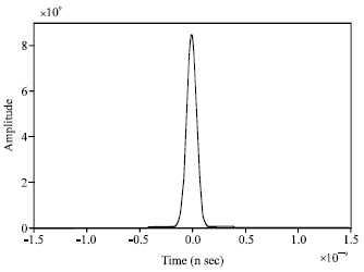
and the time-domain waveform is shown in Fig. 1 with σ = 0.04 ns.
Then the nth order derivative Gaussian pulse can be determined recursively from:
![]() | (2) |
The Fourier transform of the nth order derivative pulse is:
![]() | (3) |
Then the peak of the power spectral density (PSD) of transmitted signal is given by:
![]() | (4) |
where Amax is the PSD.
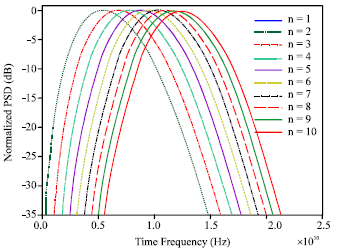
In Fig. 2, the PSD for the first-order through 10th-order derivatives of the Gaussian pulse are shown, respectively and σ = 0.04ns.
DS-UWB signal and power spectral: DS-UWB is an effective modulation way of the wireless communication and its emission signal can be expressed as (Yi et al., 2008):
![]() | (5) |
where, djε{-1, +1} is the users binary information symbols and its power spectral density is Pd(f); gnε{-1, +1} is the users pseudo-random code sequence, Rs = 1/Ts is data rate and Ts = NsTf is symbol period, then each binary data symbol is expressed by Ns single pulses.
Spreading spectral code uses m sequence and its power spectral is expressed as:
![]() | |
Fig. 1: | Gaussian pulse with σ = 0.04 ns |
![]() | |
Fig. 2: | PSD of the high-order derivatives of the Gaussian pulse |
![]() | (6) |
where Tc is chip spacing and Ts = NTc is period of PN sequence.
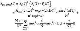
According to Eq. 4 and 6, we can get the power spectral density of nth order derivative Gaussian pulse DS-UWB signal as:
![]() | (7) |
PERFORMANCE ANALYSIS OF UWB-UAV DATA TRANSMISSION
Free space model: In the free space, the average received power of the UWB system at the receiving termination is Pr, which is given by Friis (1946):
![]() | (8) |
and the free-space loss is shown as:
![]() | (9) |
where Pt is the transmitted power, fc is the carried frequency, Gt and Gr are the transmitting and receiving antenna gains, respectively and c is the speed of light.
For the outdoor UWB transmission system applying the pulse given by Eq. 2, the PSD is very wideband. As a result Eq. 9 must be modified to account for variations across the bandwidth of the signal. Particularly, the transmitted and received power should be calculated using the integral of the PSD within a frequency region. Therefore, the transmitted power is:
![]() | (10) |
Assuming that the received signal occupies a band from fl to fh, the received power at distance d becomes:
![]() | (11) |
where, PL(d, f) is the wideband path loss for the free space propagation model. With this frequency dependent path loss, the received power is:
![]() | (12) |
Considering the AWGN channel, the minimum power required at a distance d to achieve a signal-to-noise ratio (SNR) at the receiver is given by:
![]() | (13) |
where, Pn is the noise power and it is equal to N0B and B is the receiver equivalent noise bandwidth. If each binary data symbol is expressed by 10 Gaussian pulses, the average output SNR is:
![]() | (14) |
where, Eb/N0 is the energy to noise spectral density obtained at the receiver per bit, Ns is the number of Gaussian pulses per bit and Rs is the bit rate.
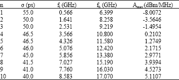
Table 1: | Summary of the parameters for UAV UWB systems |
![]() |
The relationship between the order n of Gaussian pulse and the Amax which is the peak of the signal transmit power spectral density can be obtained from Eq. 10-12:
![]() | (15) |
In our simulation, the noise spectral density is kT0F•LM = -102.83 dBm/MHz, where T0 is the room temperature (300K), k is Boltzmann constant, the noise figure is F = 6 dB and a margin LM is assumed as 5dB.
Table 1 summarizes the parameter σ, the frequencies where the spectral is 10 dB down from the peak and the Amax. All of those are calculated in the condition of the Rs is 25 Mbps, the distance between the receiver and the transmitter is 10 km, BER is 10-6 and the transmitting and receiving antenna gains are both 10dB and the selection of σ is based on limiting 99.9% of energy of Gaussian pulse within 0.5 ns.
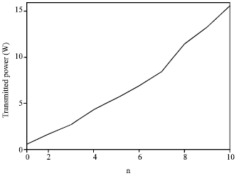
According to the data in the Table 1 and using Eq. 4, 10, 12 we can get the minimum received power for demodulation which is 14.714x10⁻³ mW. The transmission power with different orders n is shown in Fig. 3. From Fig. 3, we can see the first order Gaussian pulse has the minimum transmission power.
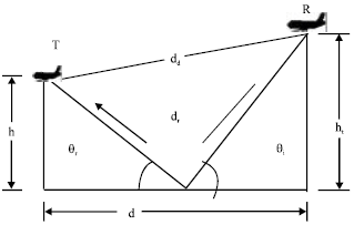
Frequency dependent two-ray path model: Although, in the current narrow and wideband system the impact of frequency dependence in the path loss may seem to be negligible, the same assumption can not be applied to UWB system, which uses extremely wide bandwidth. UAV flight attitude is low and the flight distance is relatively short. For convenience in an open area, when the UAV is in flight state, the channel can be assumed to be a two-ray path model, that there is a direct component at the same time there is a strong ground reflection component. The model is illustrated in Fig. 4 and it is suitable for open area outdoor environments.
The two-ray path loss model is given by Nascimento and Nikookar (2007):
![]() | |
Fig. 3: | The relationship between the transmitted power and n-derivative Gaussian pulse |
![]() | |
Fig. 4: | Two-ray propagation model |
![]() | (16) |
where, R(d, f) is Fresnel reflection coefficient that is defined by the ratio of energy of reflected electric field to that of incident field, d is the distance between the transmitting and receiving antennas, dd and dr are the length of direct path and reflected path, respectively and θi is the angle between the incident wave on the ground and the ground floor:
![]() | (17) |
where, ht and hr are the transmitting and receiving antenna heights, respectively. For convenience we assume that θi = θr, where θr is the angle between the reflected wave from the ground and the ground floor.
The Fresnel reflection coefficient is given in Eq. 18, considering horizontal electric field polarization:
![]() | (18) |
where, ξr(f) is the relative dielectric constant of the ground reflection material. For concrete block, the frequency dependency of the relative dielectric constants is (Nascimento and Nikookar, 2007):
![]() | (19) |
Considering Eq. 11, 16 and 18, we can get the complete two-ray path loss model.
Assuming that ht and hr are 500 m, the distance between two UAVs is d = 10000 m and the flight speed of the two UAVs is 200 m sec. When the receiver get signals, the UAV only moves 0.0067 m relatively to the transmitter and the 0.0067 m is far smaller than 10000 m, so it can be omitted. And the interval time of the two signals is 166.7 ns. As a result, the receiver we selected is rake receiver with maximum ratio combing technology.
Performance compare of free space model and frequency dependent two-ray path model: In the two-ray path model, using maximum ratio combining, each sub-set of the slip road has a variable gain amplifier to adjust the gain of the slip road. The maximum ratio requires that the signals of each users full set of slip have a same phase at the time of combining them. The weight is allocated according to the SNR of each branch, which means the branch of large SNR has a larger weight. As a result, the output has a characteristic of a square law, so it also is called square law merger. Taking the single user for example, only considering the impact of Gaussian noise, the output is:
![]() | (20) |
where r, rj and wj are users merger signal ,the slip signal and the weight, respectively. If each branch has the same average noise power N and then the total noise NT will be the weighted value of the noise of each branch:
![]() | (21) |
Therefore, after combination, the SNR is:
![]() | (22) |
It can be proved that the maximum occurs on wj = rj/N. And then we can get the combined SNR from Eq. 20, 21 and 22:
![]() | (23) |
where rj is the SNR of the branch j and L1 is the user diversity order. As a result, the SNR of the maximum ratio combining is equal to the sum of each branch.
Assuming each branch has the same SNR, E(rj) = Γ, jε{1, L1}, the combined average SNR is:
![]() | (24) |
When the signal propagates in free space, the communication channel can be viewed as AWGN channel and the best receiver is related receiver. Using BPSK modulated by DS-UWB, the system BER is:
![]() | (25) |
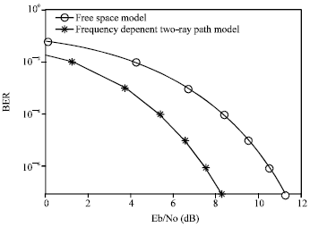
Figure 5 shows the simulation results of Per in the free space model and in the two-ray path model. Applying the Monte Carlo simulation, the baseband code rate is 25 Mbps and the simulation number is 10000.
From the Fig. 5, it can be seen that under the same SNR the two-ray path model BER is significantly lower than the free space and the system performance is improved obviously. When the BER is 10-6, the SNR of two-ray path model is 7.52 dB, which is 3.01 dB lower than the free space model. The most important reason is that the capture energy increased markedly by using maximum ratio combining rake receiver, so it greatly enhanced the performance of the system.
According to Eq. 10 and 15 the average received power of UWB two-ray path model can be expressed as:
![]() | (26) |
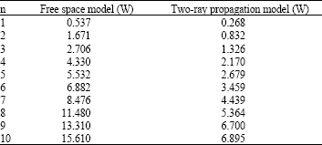
From Eq. 10, 13 and 20, we can get the minimum received power for demodulation which is 14.714x10⁻³ mW and the transmission power both in the free space model and the two-ray path model. The transmitted power is shown in Table 2, where Rs is 25 Mbps, the distance between the receiver and the transmitter is 10 km, BER is 10-6 and the transmitting and the receiving antenna gains are both 10 dB.
![]() | |
Fig. 5: | The relationship of BER and Eb/N0 in free space and two-ray propagation model |
Table 2: | Comparison of the transmitted power in free space and two-ray models |
![]() |
We can see from the Table 2 that the transmission power of two-ray path model is about half of the free space propagation model.
CONCLUSIONS
In this study, the DS-UWB technology is used for unmanned aerial vehicle communication links design. In the case of high speed and long range transmission, in order to make the transmitted power as low as possible, the first-order Gaussian pulse is the best choice. The paper analyzes the system transmission performance of the free space model and the two-ray path model. In the two-ray path model, the rake receiver is selected, which uses maximum ratio combing technology. Because of the capture energy increased markedly by applying maximum ratio combining rake receiver, the performance of the system is greatly enhanced. Moreover, the paper compares the transmitted power and the BER performance of the two-ray path model and the free space model. The results show that the two-ray path model will reduce nearly 50% of the transmitted power and with the 10-6 of the BER, its SNR is 3.01 dB lower than the free space model.
REFERENCES
- Ameti, A., R.J. Fontana, E.J. Knight and E. Richley, 2004. Ultra wideband technology for aircraft wireless intercommunications systems (AWICS) design. IEEE Aerospace Electronic Syst. Magazine, 19: 14-18.
CrossRef - Ma, Z.S., A.W. Krings and R.E. Hiromoto, 2009. Dragonfly as a model for UAV/MAV flight and communication controls. Proceedings of the IEEE Aerospace Conference, March 7-14, Big Sky, MT, pp: 1-8.
CrossRef - Wenhui, Z. and L. Jiming, 2008. UWB impulse radio signal detection with high-speed integrated comparator. Inform. Technol. J., 7: 516-521.
CrossRefDirect Link - Foerster, J., E. Green, S. Somayazulu and D. Leeper, 2001. Ultra-Wideband technology for short-or medium-range wireless communications. Intel. Technol. J. Q., 2: 1-11.
Direct Link - Jing, M., Z. Nai-Tong and Z. Qin-Yu, 2010. IR-UWB waveform distortion analysis in NLOS localization system. Inform. Technol. J., 9: 139-145.
CrossRefDirect Link - Zhao, L. and A.M. Haimovich, 2001. Capacity of M-ary PPM ultra-wideband communications over AWGN channels. IEEE VTS 54th Vehicular Technol. Con., 2: 1191-1195.
CrossRef - Agarwal, N. and R. Bhattacharjee, 2009. Internal successive reflection model for indoor UWB communication. Proceedings of the TENCON 2009 IEEE Region 10 Conference, Jan. 23-26, Department of Electronic and Communication Engineering, Indian Institute of Technology, Guwahati, India, pp: 1-5.
CrossRef - Yi, H., Y.S. Wang, X.Y. Zuo and Y.N. Zhang, 2008. Ultra wideband technology for Micro Air Vehicles data links systems. Proceedings of the ICMMT International Conference on Microwave and Millimeter Wave Technology, April 21-24, Nanjing, pp: 108-111.
CrossRef - Friis, H.T., 1946. A note on a simple transmission formula. Proc. IRE., 34: 254-256.
CrossRefDirect Link - Nascimento, J. and H. Nikookar, 2007. On the range-data rate performance of outdoor UWB communication. Proceedings of the 2nd International Conference on Wireless Broadband and Ultra Wideband Communications, Aug. 27-30, Sydney, Australia, pp: 72-72.
CrossRef - Fontana, R.J., 2004. Recent system applications of short-pulse Ultra-Wideband (UWB) technology. IEEE Trans. Microwave Theory Tech., 52: 2087-2104.
CrossRefDirect Link