ABSTRACT
In this study, a novel feedforward compensator which is based on the non-uniform rational B-splines (NURBS) curve neural network (NURBSCNN), is developed for the travelling wave ultrasonic motor (TWUSM). The proposed NURBSCNN consists of three hidden layers, in which the blending functions are adopted as the activation functions for the neurons in the first hidden layer rather than the commonly used sigmoid functions. Simulations are performed to demonstrate the feasibility of the proposed schemes. Simulation results reveal that the proposed design approach exhibits satisfactory performance.
PDF Abstract XML References Citation
How to cite this article
DOI: 10.3923/itj.2010.1671.1676
URL: https://scialert.net/abstract/?doi=itj.2010.1671.1676
INTRODUCTION
The TWUSMs have received much attention from different fields in recent years. The TWUSM has several attractive features, for example: simple mechanical structure, high holding torque, high torque output at low speed, compact in size and silent operation (Chau et al., 2003; Bal and Bekiroglu, 2004). However, the TWUSM exhibits highly nonlinear and extremely complicated characteristics so that it is hard to control (Chen et al., 2008) and therefore result in some limitations on the TWUSM applications. Although many researchers (Senjyu et al., 1998; Bal and Bekiroglu, 2004; Chen et al., 2008) have proposed numerous approaches, but unfortunately, most of them suffer from some difficulties in practical applications.
Chen et al. (2008) and Bekiroglu and Bal (2008) pointed out that there exists a nonlinear input/output characteristic curve for the TWUSM. In order to facilitate the use of the TWUSM Senjyu et al. (1998) proposed a neural network based speed control scheme to learn the inverse model of the nonlinear input/output mapping for the TWUSM.
In fact, the artificial neural network has been applied to deal with motion control problems. For example, a back-propagation network (BPN) (Lan et al., 2008) is employed to learn the cutting parameters turning for the ECOCA-PC3807 CNC lathe. Moreover, the artificial neural network (ANN) is used to predict the mean value of friction coefficient and standard deviation of the produced brake linings (Mutlu, 2009).
On the other hand, in the fields of free-form curve and surface representation, the Non-Uniform Rational B-Splines (NURBS) (Tiller, 1983; Piegl and Tiller, 1987; Piegl, 1991) has been the most popular geometric representation in computer graphics, Computer Aided Design and Computer Aided Manufacture (CAD/CAM) (Dam, 1988; Fang et al., 1997). In addition, NURBS has attracted attention from other research fields as well (Cheng et al., 2002; Cheng and Wang, 2009). In particular in motor control (Lin et al., 2006) used a 2-D input B-spline neural network with the local weight updating algorithm to learn a suitable phase current profile online for torque ripple reduction. Also, Lin et al. (2007) was employed a 2-D input B-spline neural network was employed in the online-modeling scheme of a switched reluctance motor without any priori knowledge.
In this study, we firstly develop the three hidden layers NURBSCNN as the feedfoward compensator of the TWUSM. In the NURBSCNN, the blending functions rather than the commonly used sigmoid functions are adopted as the activation functions for the neurons in the first hidden layer. From the mathematical derivation point of view, it is obvious that the mathematical expression of the output of the NURBSCNN is the same as the NURBS curve. Thus, intuitively, the proposed NURBSCNN is suitable for designing the feedfoward compensator of the TWUSM. Since the characteristic of the TWUSM depends on its rotational direction, the feedforward compensators of the TWUSM are designed for both the motions in the counterclockwise (CCW) and clockwise (CW) directions separately. Simulation results have demonstrated the feasibility of the proposed approach.
NURBSCNN
A NURBS curve (Piegl, 1991) can be expressed by:
![]() | (1) |
![]() | (2) |
where, Pi denotes the ith control point, Wi denotes the corresponding weight of Pi and (n+1) denotes the total number of control points. Moreover, Ni,p(u) is the blending function, Ri,p(u) is the single rational B-spline and p is the degree of the blending function.
The architecture of the proposed NURBSCNN for the feedforward compensator of the TWUSM is shown in Fig. 1. Similar to the approach proposed by Cheng et al. (2008), the activation functions for the neurons in the 1st hidden layer are blending functions, while those in the 2nd and 3rd hidden layers and the output layer are linear functions with unity slope. Additionally, the integration functions for the neurons in the 1st and 2nd hidden layers and in the output layer are the linear functions as well as the polynomial function (product operation). It is worthy to notice that the 3rd hidden layer only consists of two neurons. The integration function for the neuron on the top is a reciprocal function, while the integration function for the neuron
on the bottom is linear. Moreover,
denote the output and the input of the mth neuron in the rth hidden layer, respectively. In addition, Or(•) and Ir(•) represent the output and the input of the neurons in the rth hidden layer, respectively.
The outputs of the neurons in the 1st hidden layer can be expressed as:
![]() | (3) |
Because the activation functions for all the neurons in the 2nd and 3rd hidden layers are linear, the outputs of the neurons in the 2nd and 3rd layers can be described as follows:
![]() | (4) |
![]() | (5) |
![]() | (6) |
It is obvious that the integration function for the output layer is a product function, thus the output of the neural network can be expressed as:
![]() | (7) |
Substituting Eq. 3 and 4 into 7, one can obtain:
![]() | |
Fig. 1: | The proposed three-hidden-layer NURBSCNN for learning control points Pi and weights Wi of NURBS curves; Π: product operator; Σ: summation operator; 1/Σ: reciprocal operator |
![]() | (8) |
Clearly, Eq. 8 is exactly the same as the NURBS curve in Eq. 1. Therefore, Eq. 8 will be exploited to learn proper values of control points and weights so that the NURBS curve resulting from the NURBSCNN can appropriately describe the inverse relationship between the input and output of the TWUSM as well.
Now, define the cost function E(P,W) as:
![]() | (9) |
where Vk is the desired output, is the output of the NURBSCNN and k ranges from 1 to K. With Eq. 3-9 and the back-propagation learning scheme (Cheng et al., 2008), the learning rule for the control points Pi with the learning rate η and weights Wi with the learning rate λ can be expressed as Eq. 10 and 11, respectively.
![]() | (10) |
![]() | (11) |
DESIGN OF THE FEEDFORWARD COMPENSATOR FOR THE TWUSM BASED ON NURBSCNN
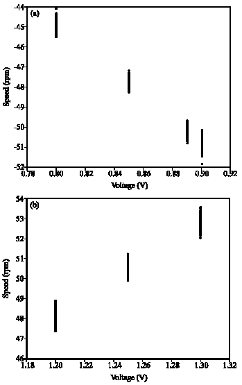
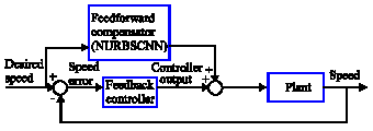
The voltage-speed characteristic curves of the TWUSM system measured at some specific voltages for both the motions in the CCW and CW directions are shown in Fig. 2a, b. It can be clearly seen that the voltage-speed characteristic curve of the TWUSM is highly nonlinear. This nonlinearity seriously hampers the feasibility of the TWUSM when used in motion control applications. One of the popular approaches to cope with this difficulty is to employ an inverse model based feedforward compensator. In this study, a feedforward compensator based on NURBSCNN is proposed to deal with the nonlinearity of the TWUSM. Figure 3 illustrates the block diagram of the proposed feedforward compensator for the TWUSM when applied to speed control problems.
For the TWUSM system investigated in this study, its input and output are the voltage Vk and the angular velocity ωk, respectively.
![]() | |
Fig. 2: | Voltage to speed characteristic curves for the real TWUSM system. (a) Characteristic curves in the CCW direction measured at 0.8, 0.85, 0.89 and 0.9V. (b) Characteristic curves in the CW direction measured at 1.2, 1.25 and 1.3V |
![]() | |
Fig. 3: | Block diagram of the proposed feedforward compensator for the TWUSM when applied to speed control problems |
The goal here is to use Eq. 8 to learn the speed-voltage characteristic curve (ωk, Vk). Namely, for any desired parameter it is aimed at finding a suitable NURBS curve C(
) to approximate the output data Vk. That is:
![]() | (12) |
where, is the primary parametric input data of the nonlinear TWUSM system. By the learning mechanism of the NURBSCNN, the control points and weights can be adjusted to accomplish the learning goal so as to obtain the data as close to the original output data Vk as possible. In this study, by taking a similar design concept (Senjyu et al., 1998), a feedforward compensator which can represent the inverse model of the TWUSM is constructed.
In order to achieve satisfactory performance when utilizing the NURBSCNN, the parameterization needs to be deliberately executed in advance. In general, the parameters (Cheng et al., 2008) should reflect the distribution of the original data ωk after parameterization. In this study, the uniformly spaced method (Lee, 1989) is adopted to perform parameterization. Using the uniformly spaced method, all the collected input data ωk are mapped into the corresponding parameters
as described in Eq. 13 and 14:
![]() | (13) |
![]() | (14) |
where, N denotes the total number of the original input data ωk and ωM denotes the maximum of the absolute value of the original input data ωk.
After is decided, the averaging method (Piegl, 1991) which is described as Eq. 15 and 16 is exploited to determine the corresponding knot values
![]() | (15) |
![]() | (16) |
where, the definition of p and r are consistent with description in the mentioned NURBS above. Eq. 16 provides a means to determine the internal knots of the NURBSCNN so that the knots are distributed uniformly.
After performing parameterization and determining the knot vector, the unknowns to be solved in the NURBSCNN described by Eq. 12 are the control points Pi and the weights Wi. It is worth to notice that the total numbers of Pi and Wi in the NURBSCNN are the same. In this study, in order to simplify the learning process, Wi are set to one.
![]() | |
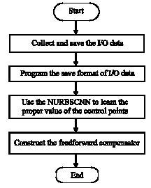
Fig. 4: | Flowchart of the design procedure for the proposed TWUSM feedforward compensator |
Thus, the only unknowns in the NURBSCNN are the control points Pi. In addition, Eq. 10 is employed to obtain the proper values of the control points Pi so that the error between Vk and C() is as small as possible. In general, more control points are needed for a complicated mapping function however it will increase the computational load. In contrast, fewer control points are required for a simple mapping function since it requires less computational load.
The flowchart of the design procedure for the proposed TWUSM feedforward compensator is illustrated in Fig. 4.
SIMULATION RESULTS AND DISCUSSION
The data used for simulation are collected from a real TWUSM system. This system consists of a USR60 ultrasonic motor manufactured by SHINSEI Co. and a built-in driver equipped with an optical encoder with 2000ppr resolution. In this study, peripheral circuits are designed and constructed to implement the proposed feedforward compensator architecture for speed control in both the CCW and CW directions. In addition, a PC-based motion card with EPCIO-4000 manufactured by Industrial Technology Research Institute (ITRI) is used to acquire voltage signals and rotational speed commands of the TWUSM. The position information of the TWUSM is sampled once per 10 m sec and is used to calculate the corresponding motor speed via the LSF 1/4 method (Brown et al., 1992). In the simulation, the original data from the TWUSM system is acquired with 6 sec duration. Namely, the total number of data pairs (Vk, ωk) is 1200 for both the motions in the CCW and CW directions. After the position data is obtained, one can calculate the rotational speed of the TWUSM. Besides, the rated speed of the chosen TWUSM is 100 rpm for both the motions in the CCW and CW directions, thus the simulations of the proposed TWUSM feedforward compensators are performed under this speed range. Since the characteristics of the TWUSM for both the motions in the CCW and CW directions are different, they will be investigated separately in the simulations. Nevertheless, for convenience, the NURBSCNN parameter settings listed in Table 1 are set to the same for both cases throughout the simulation.
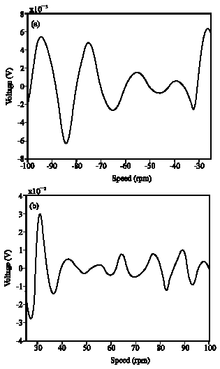
Simulation results are illustrated in Fig. 5. In particular, Fig. 5a shows the error between the data points and the NURBSCNN for the motion in the CCW direction,while Fig. 5b shows the error between the data points and the NURBSCNN for the motion in the CW direction.
Table 1: | NURBSCNN parameters setting |
![]() | |
![]() | |
Fig. 5: | Simulation results of the NURBSCNN. (a) Error between the data points and the NURBSCNN for the motion in the CCW direction. (b) Error between the data points and the NURBSCNN for the motion in the CW direction |
From the simulation results, one can easily find out that the maximum error is under ±7 mV (±0.42 rpm) for the CCW direction while the maximum error is less than ±3 mV (±0.15 rpm) for the CW direction. Since, the resolution of voltage signal for the speed response of the real TWUSM is around 10 mV, the proposed NURBSCNN indeed exhibits satisfactory performance. In addition, the simulation results also reveal that the feedforward compensator has different characteristics at different rotational directions.
CONCLUSION
We have proposed a NURBSCNN with a three-hidden-layer feedforward structure for TWUSM. The back-propagation algorithm is used to learn the control points of the NURBSCNN to approximate the speed-voltage characteristic curve of the TWUSM. Simulation results have demonstrated the effectiveness and feasibility of the proposed approach.
REFERENCES
- Bal, G. and E. Bekiroglu, 2004. Servo speed control of travelling-wave ultrasonic motor using digital signal processor. Sensors Actuators A: Physical, 109: 212-219.
CrossRef - Bekiroglu, E. and G. Bal, 2008. Experimental investigation of input-output characteristics of a travelling-wave ultrasonic motor. J. Electroceramics, 20: 287-292.
CrossRef - Brown, R.H., S.C. Schneider and M.G. Mulligan, 1992. Analysis of algorithms for velocity estimation from discrete position versus time data. IEEE Trans. Indus. Electronics, 39: 11-19.
CrossRef - Chau, K.T., S.W. Chung and C.C. Chan, 2003. Neuro-fuzzy speed tracking control of traveling-wave ultrasonic motor drives using direct pulsewidth modulation. IEEE Trans. Indus. Appl., 39: 1061-1069.
CrossRef - Chen, T.C., C.H. Yu, C.J. Chen and M.C. Tsai, 2008. Neuro-fuzzy speed control of traveling-wave type ultrasonic motor drive using frequency and phase modulation. ISA Trans., 47: 325-338.
CrossRef - Cheng, M.Y., M.C. Tsai and J.C. Kuo, 2002. Real-time NURBS command generators for CNC servo controllers. Int. J. Mach. Tools Manufacture, 42: 801-813.
CrossRef - Cheng, M.Y., H.W. Wu and A.W.Y. Su, 2008. On non-uniform rational B-splines surface neural networks. Neural Process. Lett., 28: 1-15.
CrossRef - Cheng, M.Y. and Y.H. Wang, 2009. Velocity field construction for contour following tasks represented in NURBS form. IEEE Trans. Automatic Control, 54: 2405-2410.
CrossRef - Dam, A.V., 1988. PHIGS+, functional description revision 3.0. ACM SIGGRAPH Comput. Graphics, 22: 125-220.
CrossRef - Fang, M.L., D.F. Chen and B.Y. Zhu, 1997. Model reconstruction of existing products using neural networks for reverse engineering. Proceed. IEEE Int. Conf. Intel. Process. Syst., 1: 396-400.
CrossRefDirect Link - Lan, T.Y., C.Y. Lo, M.Y. Wang and Y.A. Yu, 2008. Multi-quality prediction model of CNC turning using back-propagation network. Inform. Technol. J., 7: 911-917.
CrossRefDirect Link - Lee, E.T.Y., 1989. Choosing nodes in parametric curve interpolation. Comput. Aided Des., 21: 363-370.
CrossRef - Lin, Z.Y., D.S. Reay, B.W. Williams and X.N. He, 2006. Torque ripple reduction in switched reluctance motor drives using B-spline neural networks. IEEE Trans. Ind. Appl., 42: 1445-1453.
CrossRef - Lin, Z.Y., D.S. Reay, B.W. Williams and X.N. He, 2007. Online modeling for switched reluctance motor using B-spline neural networks. IEEE Trans. Ind. Electronics, 54: 3317-3322.
CrossRef - Mutlu, I., 2009. Artificial neural networks modelling of non-asbestos brake lining performance boric acid in brake pad. Inform. Technol. J., 8: 398-402.
CrossRefDirect Link - Senjyu, T., H. Miyazato, S. Yokoda and K. Uezato, 1998. Speed control of ultrasonic motors using neural network. IEEE Trans. Power Electronics, 13: 381-387.
CrossRef - Tiller, W., 1983. Rational B-splines for curve and surface representation. IEEE Comput. Graphics Appl., 3: 61-69.
CrossRef