INTRODUCTION
In recent times, nickel based alloys like Inconel 718 are gaining importance
in making of gas turbines, space crafts, rocket motors, nuclear reactors etc.
These classes of materials, being strong, light weight and aesthetic in appearance
represent an excellent choice specifically for construction of aerospace components
(Habeeb et al., 2008). However, nickel based
super alloys are among the work materials with the lowest machinability properties.
They are specifically designed to retain high strength at elevated temperatures
due to which higher cutting forces are encountered as compared to steel. The
low thermal conductivity of nickel alloys give rise to high temperatures as
compared to steel material is another issue. These lead to difficulty in machining
of these alloys using conventional techniques (Shaw, 1997).
As a result, EDM process becomes a natural choice for machining of nickel based
super alloys. Electro Discharge Machining (EDM) is one of the most successful,
profitable and extensively used non conventional machining processes for high
degree of dimensional accuracy and economical cost of production of any conductive
material irrespective of its hardness. It is particularly advantageous in manufacturing
of moulds, dies, automotive, aerospace and surgical components owing to its
unique feature of using thermal energy to machine electrically conductive parts
regardless of its hardness (Ho and Newman, 2003).
In EDM process, Material removal and its mechanism has been one of the main
concerns for several years. Since the development of this process, researchers
have explained the material removal mechanism by developing different thermal
models by considering relationship between pulse conditions and material removal
by solving time dependent heat transfer equations based on various assumptions
based on different heat source models (Snoeys and van Dijck,
1971; Snoeys et al., 1972; Erden
and Kaftanoglou, 1981; Patel et al., 1989).
All of these and most of the many other theoretical models are concerned with
die sinking EDM process which shows large discrepancy between the predictions
and the experimental results due to simplified and unavoidable assumptions.
Many attempts have been made in recent past to develop empirical models for
EDM process (Pei-Jen and Kuo-Ming, 2001; Dhar
et al., 2007; Doniavi et al., 2008;
Sarkar et al., 2008; Chattopadhyay
et al., 2009).
However, literature related to the study of EDM process under orbital tool
actuation is limited. Most of the reported literature is based on the study
of process capabilities of orbital EDM as compared to cavity sinking EDM (Rajurkar
and Royo, 1989a, b; Yu et
al., 2002; Bamberg et al., 2005; El-Taweel
and Hewidy, 2009). These researchers and many others (Rahman
et al., 2011) have attempted to work on various grades of steel and
very few have attempted to work on superalloy metal. No attempt to develop theoretical
and/or empirical model considering orbital tool movement has been reported to
the best of the authors knowledge. The present study is an attempt to
bridge this gap. In this paper, a systematic and simplified approach is used
for model development and analysis of MRR with various machining parameters
and orbital parameters. Taguchi based experimental approach has been employed
to design the experimental plan.
ORBITAL EDM
Orbital tool actuation in EDM process helps to decouple the size of the electrode
from the size of the feature to be machined. An electrode that is significantly
smaller than the cavity to be generated can be actuated on a tool path that
will articulate its outer surface on a trajectory equal to the shape of the
hole. Hence, a standard electrode can be used to drill a wide range of holes
while the increased clearance between the hole and the electrode helps getting
the dielectric fluid to the bottom of the hole. The use of a small size of standard
electrodes instead of matched electrodes for every single hole size drastically
reduces tooling efforts. The improved flushing will reduce recasting of removed
material which tends to diminish surface quality (Guitrau,
1997).
Joemars make ZNC EDM with orbit cut mechanism is used in present study. The machine has the capability to control Z-axis movement with precision upto 1 μm. The orbital cut mechanism can control X and Y axis movement independently with same precision.
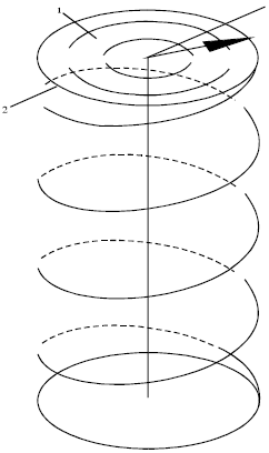
In present study, orbital movement is actuated along helical path as shown in Fig. 1. Over and above this, the mechanism has a capability to initiate the movement on orbital path at 10 different speeds ranging between 0.04 to 0.36 mm sec-1 at the central point of electrode.
EXPERIMENTAL DETAILS
Workpiece and tool electrode: Inconel 718 is taken as work piece materials and electrolyte copper is taken as electrode material. The properties and compositions of Inconel 718 are summarized in Table 1.
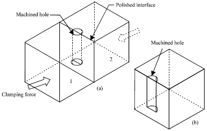
The work piece is cut into the size of 13x13x10 mm. Two work pieces are clamped
together as shown in Fig. 2 and hole is drilled at the interface
of two polished surfaces of the work piece.
Table 1: |
Chemical composition of Inconel 718 |
 |
|
Fig. 1: |
Helical path traced during orbital tool actuation |
|
Fig. 2(a-b): |
Work piece design and method of application |
The split work piece enables easy separation after machining and hence opens
the internal surface for further study.
Copper electrode is fabricated to a length of 20 mm with varying diameter of
5, 6, 7, 8 and 9 mm. Each tool with a specific diameter is given orbital movement
at a orbital radius so as to split generate a circular hole of 10 mm diameter
upto a depth of 10 mm.
Table 2: |
Parameters and their level |
 |
Commercially available dielectric fluid is used during the experiments.
Parameter selection: The process parameters chosen for the present experiment are: (A) Orbital Radius Ro, (B) Orbital Speed So, (C) Current I, (D) Gap Voltage Vg, (E) Pulse ON time ton and (F) Duty Factor DF. These parameters were selected because they can potentially affect Material Removal Rate during EDM operation. The machining conditions and number of levels of the parameters are selected as given in Table 2.
Response selection: MRR (mm3/min) is calculated by weight difference of the work piece before and after machining using a precision weighing machine (maximum capacity = 300 g, least count = 1 mg).
The Equation used for calculating MRR is as under:
where, Wwi and Wwf are initial and final weights of work piece, respectively; ñw is density (g mm-3) of work piece and t is the machining time (min).
The objective of this experimental study is to determine the machining conditions
required to achieve maximum Material Removal Rate (MRR) under orbital tool motion
in EDM process. Therefore, quality characteristic of larger the better (LB)
for MRR is implemented in this study. The S/N ratio (η) is calculated using
the Eq. 2 given as under:
For LB characteristics:
where, yij is the response of ith quality characteristics at jth experimental run and n is the total number of repetition of a run.
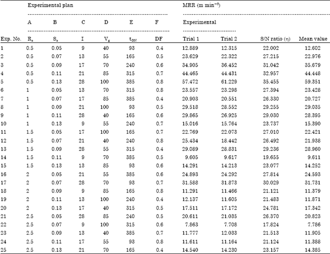
The experimental plan is designed as per L 25 orthogonal array which considers 6 parameters each at 5 levels. The experimental plan is shown in Table 3. All experimental runs have been conducted twice for effective S/N ratio calculation. The mean and S/N ratio of MRR are also shown in Table 3.
Table 3: |
L 25 table and observed values |
 |
EMPIRICAL MODELING OF ORBITAL EDM PROCESS
Empirical expressions have been developed for evaluating the relationship between input and output parameters. The mean output values for MRR are used to construct the empirical expressions.
The functional relationship between a dependent output parameter viz., MRR with the input independent parameters viz., orbital radius, orbital speed, current, gap voltage, pulse ON time and duty factor can be postulated using the following Eq. 3:
where, Y is a dependent parameter viz., MRR; X1, X2, X3, X4, X5 and X6 are independent parameters viz., orbital radius, orbital speed, current, gap voltage, pulse ON time and duty factor; a,b,c,d,e and f are power indices of the respective terms and A is a constant.
The above non linear Eq. 3 can be converted into linear form by logarithmic transformation of Eq. 4 as under:
The above Eq. 4 can be rewritten as under:
where,
is the true value of the dependent machining output on a logarithmic scale;
x1, x2, x3, x4, x5 and
x6 are the logarithmic transformations of the different input parameters;
β0, β1, β2, β3,
β4, β5 and β6 are the corresponding
parameters to be estimated.
Gauss Newton algorithm has been used to estimate the parameters of the above first order model using the data shown in Table 3. The developed empirical model for MRR is given below:
The predicted MRR for each experiment have been calculated and verified for the closeness between actual and predicted values. The adequacy of the empirical model presented in Eq. 6 is checked and validated by the mean error (Emean), Standard deviation (σdev) or Root mean square error and average percentage error (Eavg) which, are given as under:
where:
where, Xi is the ith result obtained from the model and X is the corresponding experimental result, n is the total number of observations considered in present case i.e., 25.
The value of Emean is found to be -0.042 and the value of Eavg (%) is found as 0.46%. These values show that the model is very well suited for predicting MRR in EDM during orbital tool actuation.
Further, the observations of M.R.R. for Inconel 718 are checked for existence
of any objectionable data points which may be rejected using Chauvenets
criterion (Taylor, 1997) which, states that An observation
may be rejected if the probability of obtaining the particular deviation from
the mean is less than 1/2n.
Based on Chauvenets criterion, it is found that there is no observation in AISI 304 required to be rejected. However, one observation in Inconel 718 is rejected. Hence, the revised standard deviation comes out to be 9.41 which, are better than the standard deviation shown in Table 4.
Table 4: |
Adequacy check of empirical model |
 |
Table 5: |
ANOVA for MRR of Inconel 718 |
 |
Thus, it can be noted that the proposed empirical model also fits well with the observations recorded during Taguchi approach based experiments. This is evident from very less average error found in the models.
ANALYSIS OF VARIANCE (ANOVA)
The basic idea behind analysis of variance is to breakdown total variability
of the experimental results into components of variance and then to assess their
significance by comparing them with the residuals. The F-test is carried out
to compare the variance attributed to a particular factor effect with the variance
attributed to the residual (Montgomery, 1997). Standard
values of F can be obtained from standard tables of statisticians depending
on the desired confidence level. If the calculated F ratio values exceed the
standard values, then the contribution of the respective input parameter is
considered to be significant. In present case, analysis of variance has been
carried out based on the theory proposed by Phadke (1989).
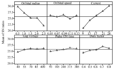
The main effect plot for MRR of Inconel 718 is shown in Fig. 3 and the ANOVA table for MRR of Inconel 718 is given in Table 5.
From Fig. 3, it is found that best MRR is obtained at minimum orbital radius of 0.5 mm. In present study, variation in orbital radius is taken in such a way that final dimension of the generated cavity remains same. Thus, when orbital radius increases, there is reduction in tool diameter. It is observed that as the orbital radius increases (i.e., tool electrode diameter reduces), there is sharp reduction in MRR. When orbital radius is more, there is relatively more open space available between the circumference of tool and cavity being generated. Thus, the side gap across periphery is not uniform which results in to reduction in effective sparks occurring around the electrode cylindrical surface. Further, there is improvement in flushing due to large space available between tool and workpiece surfaces. This results in faster removal of eroded particles. This reduces the occurrence of secondary sparks which generally contribute in high MRR during cavity sinking EDM.
|
Fig. 3: |
Main effect plot for MRR of Inconel 718 |
From the Table 5, it is found that current is the single most significant parameter that affects MRR followed by orbital radius. Thus, it can be seen that just as cavity sinking EDM, current remains the most significant parameter in orbital EDM. Orbital radius proves to be more significant parameter than any other machining parameters which lead to the fact that orbital radius can greatly affect MRR.
CONCLUSION
Attempt has been to study the effect of orbital parameters viz., radius and speed during EDM process by carrying out experiments based on Taguchi approach. Empirical model has been developed for predicting MRR which matches well with the experimental results. Thus, it can be used for MRR prediction in selected range of process parameters.
The significance of parameters involved has been checked through ANOVA technique. It is found that current along with orbital radius have significant effect on MRR.
ACKNOWLEDGMENT
The authors are thankful to Department of Science and Technology, Government of India for financial support for this work through the research grant vide grant permission SR/S3/MERC-0044/2010(G).