
Bharathi Dasaradhan
Defence Materials and Stores Research and Development Establishment (DMSRDE), G.T. Road, 208013 Kanpur, Uttar Pradesh, India
Biswa Ranjan Das
Defence Materials and Stores Research and Development Establishment (DMSRDE), G.T. Road, 208013 Kanpur, Uttar Pradesh, India
LiveDNA: 91.5718
Mukesh Kumar Sinha
Defence Materials and Stores Research and Development Establishment (DMSRDE), G.T. Road, 208013 Kanpur, Uttar Pradesh, India
Kamal Kumar
Defence Materials and Stores Research and Development Establishment (DMSRDE), G.T. Road, 208013 Kanpur, Uttar Pradesh, India
Brij Kishore
Defence Materials and Stores Research and Development Establishment (DMSRDE), G.T. Road, 208013 Kanpur, Uttar Pradesh, India
Namburi Eswara Prasad
Defence Materials and Stores Research and Development Establishment (DMSRDE), G.T. Road, 208013 Kanpur, Uttar Pradesh, India
Asian Journal of Textile
Year: 2018 | Volume: 8 | Issue: 1 | Page No.: 1-12


ABSTRACT
This review article presented a brief introduction and features of the Aerostat and the inflatable textile and polymeric materials used for developing envelope structure. Aerostat is basically an inflatable balloon fly at certain height and carries necessary items for collecting the ground information and transmitting the same to the defence source unit. The envelope used to fill with light air in pressurized condition to provide the desire lift. This review article also summarized various classes of aerostats, different components of aerostat, property requirements, fabrication methods and evaluation methods for the envelope structure. The functional features of various materials used for different components of aerostat meeting the very stringent requirements are briefly discussed. The aerostat was subjected to open environmental condition, hence the material selection for developing such structure with better durability was the matter of worry for the researchers for last few decades and some developments in this segment is evolved and brought out very broadly in this article. The fabrication methods for assembling together different layers of laminate structure and joining techniques for different parts of aerostat were also discussed. The different components of aerostat were developed with laminated fabrics of different aerial densities but with similar functions. This article also explained the different layers of the laminated fabrics with their material and functional features. The recent developments occurring worldwide and the status in Defence Research and Development Organization (DRDO) for developing envelope structure were explored.
PDF Abstract XML References Citation
Received: May 24, 2018;
Accepted: August 01, 2018;
Published: October 27, 2018
Copyright: © 2018. This is an open access article distributed under the terms of the creative commons attribution License, which permits unrestricted use, distribution and reproduction in any medium, provided the original author and source are credited.
How to cite this article
Bharathi Dasaradhan, Biswa Ranjan Das, Mukesh Kumar Sinha, Kamal Kumar, Brij Kishore and Namburi Eswara Prasad, 2018. A Brief Review of Technology and Materials for Aerostat Application. Asian Journal of Textile, 8: 1-12.
DOI: 10.3923/ajt.2018.1.12
URL: https://scialert.net/abstract/?doi=ajt.2018.1.12
DOI: 10.3923/ajt.2018.1.12
URL: https://scialert.net/abstract/?doi=ajt.2018.1.12
INTRODUCTION
Aerostat is an aerodynamically shaped non-rigid/flexible structure. The aerostats may be tethered or un-tethered. The lighter than air (LTA) helium gas is used to create the upward positive lift of the aerostat structures1,2. The Archimedes’ principle of buoyancy involved in creating the aerostat lift3,4 is shown in the following Fig. 1.
They are actually employed at greater heights to achieve certain purposes5. In actual operation, these structures will be subjected to different mechanical stresses and harsh environmental conditions where they are exposed to high level of sunlight, temperature, water and moisture6. The developed aerostat structure should be able to remain aloft in these extreme conditions while maintaining its functionality and endurance7. The wide range of applications is constantly increasing the weight of payload on the aerostat platform. So the envelope material with high-strength to weight ratio should be achieved so as to maximize the payload capacity and also to bear the envelope stress. The aerostat structure basically comprises three distinct segments, hull, fin and ballonet. A representative image of the aerostat is shown in the Fig. 2. Hull is the main balloon containing helium gas. Hull shape is the critical factor which determines the net stress acting on the structure which in-turn affects the payload carrying capacity and efficacy of the system8. Adequately sized fins are attached to the hull body for stabilizing the structure during wind disturbances5,8,9. Fins are also formed of high strength material laminated with flexible films. Aerostats employed at an altitude of 15,000 feet are subject to extreme change in atmospheric temperature and pressure.
 | |
| Fig. 1: | Schematic diagram of Archimedes’ principle involved in aerostat lift |
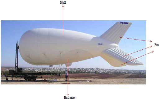 | |
| Fig. 2: | Representative image of aerostat system |
In these high altitudes, Ballonet which is an air-filled compartment is used within the hull structure to maintain aerodynamic shape of the aerostat by controlling its internal pressure. This is achieved by varying the ballonet volume with the use of blowers and valves5,10. A differential pressure sensor senses the internal envelope pressure. According to the sensed pressure, the valves or blower are activated to control the pressure change of the helium gas beyond a certain value, thus maintain the shape of the aerostat envelope11,12.
Aerostats has been used for a number of civilian as well as military applications, surveillance, security and control, tactical communication relay, personnel location and tracking, broadcasting of an event, advertising and police patrolling in cities1,3,6,7. The limited on-station time and the operational cost limit the use of multiple aircrafts for these applications3,6,13.
AEROSTAT CLASSES
Based on the load carrying capacity, deployment height and the volume, the aerostat can be grouped into three main classes.
Tactical aerostat systems: These aerostats are designed to lift a payload of around 60 lbs to an altitude of around 1000 feet. The balloon volume is around 6000 cubic feet. The flight duration with adequate free lift can be achieved for around 5-7 days, after which some helium addition should be done to maintain the lift of the balloon. In airborne state they can withstand 40 knot wind speed and in moored condition they can survive 50 knot wind speed14.
Operational aerostat systems: Operational class aerostat systems are medium-sized aerostats that are deployed at altitudes of 3,000-5,000 feet with a payload range of 300-800 lbs. The hull volume ranges from 800-1600 cubic meters depending on the payload load weight and the deployment height. The typical flight duration is more than 7 days which can be extended up to 4 weeks upon helium addition to the aerostat. This class of aerostat is designed to withstand 50 knot winds in air-borne state and 70 knot wind in moored state15.
Strategic aerostat systems: Strategic class of aerostat systems includes some of the largest tethered aerostats. They can lift a payload of around 3500-7000 lbs to an altitude of around 10,000-15,000 feet above the sea level. This class of aerostat has long flight duration and remain deployed continuously for around 30 days16.
PROPERTY REQUIREMENTS FOR AEROSTAT
For high altitude deployments, the envelope material should possess the following properties6,17-19:
| • | First and foremost, the envelope material should exhibit low gas permeability. This minimizes the helium loss thereby increasing the deployment time |
| • | The envelope material should be light weight to decrease the overall weight of the structure. This aids in maximizing the payload capacity |
| • | Sufficient strength is necessary to withstand different stresses acting on the hull structure |
| • | High tear resistance is important to maximize the damage tolerance. High tear strength is required because even small tears that are induced during handling or installing can lead to catastrophic failure of the entire system |
| • | These materials that are employed at high altitude should withstand wide temperature and pressure variations without any changes in their physical and strength properties. The material should retain its flexibility over wide range of temperature variation |
| • | It should also be resistant to environmental degradation factors such as Ultraviolet (UV), ozone, humidity, heavy winds and extreme weather conditions. This improves the self-life of the structure |
| • | The structure should also show excellent creep resistance to maintain the balloon shape throughout its entire life |
| • | The fabric will be subject to bending forces during inflation and deflation process and also in aloft condition. So the structure should be resistant to flex-fatigue |
| • | To prevent delamination, the layers of the structure should have good adhesion with the adjacent layers. Good joint performance is necessary to maintain the integrity of the structure |
The design of the aerostat structure should meet all the above mentioned properties for long-term use in all environmental conditions. This cannot be achieved with a single layer structure, so a multi-layer laminate structure is desirable6. The fabrication methods must produce a consistent structure over time with minimum variation of its performance properties. This can be easily achieved when fabrication is done in accordance with some specified standards20.
HULL MATERIAL CONSTRUCTION
To meet all the desirable properties there is a need for the envelope of the aerostat to be made of multi-layer flexible laminate material17,21.
 | |
| Fig. 3: | Multi-layer structure of typical hull material |
| Table 1: | Comparison of high performance fibres |
 | |
| PIPD: Polyhydroquinone-diimidazopyridine, PBO: Polybenzoxazole, PE: Polyethylene, LCP: Liquid crystal polymer | |
Typical construction of hull material is shown in the Fig. 317.
This multi-layer laminate represents a structure composed of an interior load-bearing layer, a gas barrier layer and an exterior environmental protection layer. These layers are bonded with its adjacent layers either chemically or mechanically or by use of some polymeric materials like polyurethanes (PU) while retaining all the desirable properties of the laminate structure17. Ideally, all the layers of the laminate structure should show same degree of deformation under stress and behave as single structure to achieve better performance of the structure22.
MATERIALS OVERVIEW
Load-bearing layer: The load-bearing or strength layer is usually composed of single or multiple layer(s) of woven fabric10. When multiple fabric layers are used they are usually biased at some angle relative to each other. This biasing provides good dimensional stability but ply separation and decreased strength to weight ratio adds problem to the structure.
Cotton fabrics were used in conventional aerostat system. Technological advancements slowly replaced those conventional materials with newly developed materials. The advancements in the properties of the synthetic fibres or polymers made them suitable choice to be used in the strength layer. The synthetic fibres have high strength-to-weight ratio which is one of the most desirable properties for the aerostat application10. Commercially available high- modulus synthetic fibres include polyesters, polyamides, aramids, liquid crystal polymers, polybenzoxazole and ultra-high molecular weight polyethylene21. High performance fibres like M5, Vectran, Zylon, Dyneema and Spectra may also be employed10,21. The performance properties of various high performance fibers have been compared in Table 1.
Researchers have carried out several experiments to study the compatibility of high performance fibers in the aerostat structure. They found that Vectran fits all the property requirements of the fiber to be used in the load bearing layer of the multi-layer laminate. They show excellent resistance to abrasion and flex-fatigue. They have better overall properties compared to other high performance fibres and can be used without any property change over longer period of time19. The superior properties of Vectran fibre which makes it the best choice for the aerostat application are summarized below:
| • | High strength to weight ratio |
| • | Excellent tear resistance |
| • | Excellent creep resistance |
| • | Good abrasion resistance |
| • | Excellent flex-fatigue resistance |
| • | Good thermal management |
| • | Minimal moisture absorption |
| • | Excellent chemical resistance |
| • | Consistent properties over wide range of temperature |
| • | High impact resistance |
The selection of weave design also affects the final properties of the laminate structure. The advantages and drawbacks of some of the weaves have been discussed below19:
| • | Plain weave, the most common and simplest pattern provides high strength and dimensional stable fabrics due to their high frequency of interlacements |
| • | The basket weave which is a derivative of the plain weave provides relatively less thickness and high tear strength compared to plain weave |
| • | The rip-stop weave is similar to the plain weave but the base yarns at regular intervals will be replaced with thicker yarns to prevent the tear propagation. Durney23 in his research work studied the use of rip stop weave to prevent the propagation of local tear in large aerostat envelope |
| • | Tri-axial fabric is a special weave where the fabric is woven from three sets of yarns. These fabrics show isotropic properties in all directions |
| • | Leno weave is an open weave with excellent dimensional stability and very high modulus and strength. |
| • | Twill and satin weaves are rarely used due to their poor dimensional stability |
Gas barrier layer: The gaps in the woven fabric of the strength layer should be sealed completely to achieve the gas barrier property. This can be done either by coating the fabric with suitable polymeric material or by laminating thin polymeric films with the strength layer19. The polymer material should have good bond-ability with its adjacent layers10. Good shear stiffness is also important to provide stability to the laminate structure9,10.
All polymers based on their chemical constitution are characterized with a particular phase transition temperature below which material becomes glassy and above which the material turns into soft rubbery state. This transition temperature is around -5°C for aromatic polymers and -50°C for aliphatic polymers. So the polymer should be carefully selected based on application temperature otherwise it may deteriorate the properties of the laminate structure.
The commonly used gas barrier material includes neoprene, poly vinyl fluoride and poly-urethane. Polyester film (Mylar®) having high tensile modulus, good shear stiffness and excellent gas barrier properties makes it suitable for aerostat applications6,19,24. The polyimide (KaptonTM) film layer has been used as gas barrier layer in their laminate construction for the LTA vehicles. It acts as an excellent gas barrier layer holding the inflating gas within the hull structure18. KaptonTM is primarily used for high temperature applications. Its excellent dielectric constant helps in diffusing the enemy targeting treats like laser light. The polyimide polymer layer degrades on exposure to UV light so it has to be over coated with an UV stable polymeric layer18.
Poly vinyl copolymers also have excellent barrier properties but it is rarely used in aerostats due to its poor flex properties at low temperature6,10. Poly-urethane (PU) and its derivatives act as an excellent gas barrier material with all properties conforming to the requirements of LTA vehicles6,10,17. The advantages of using PU coat are summed below25:
| • | PU has high toughness and possess superior mechanical properties (high tensile and tear strength, high impact resistance and very good abrasion resistance) |
| • | They have good weather-ability |
| • | They retain their flexibility even at low temperatures |
| • | They show good bond-ability with textile substrates |
The gas barrier properties of the polymeric films can be greatly enhanced by incorporation of nano-scale fillers having good aspect ratio (length to thickness ratio or surface area to volume ratio) into the polymer matrix. The incorporation of nano-fillers produces tortuous path (Fig. 4) which suppresses the movement of gas molecules across the gas barrier layer. Higher gas barrier properties of polymer nano-composites (PNCs) can be achieved with higher tortuosity created by the nano-fillers26-28.
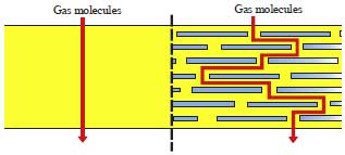 | |
| Fig. 4: | Illustration of gas transport mechanism through pure polymer and nanomaterial incorporated polymer |
Also, the incorporation of nano-elements of high aspect ratio into the polymer matrix produces an ultra large interfacial area between the incorporated nano-elements and the base polymer matrix which leads to superior properties of the nano-composite compared to conventional materials27.
Nanoclay has been widely used for gas barrier applications. However, the clay particles being hydrophilic in nature agglomerate easily. This even deteriorates the intrinsic properties of the base polymer material26. This clay agglomeration can be overcome by modifying it with transition metal ions. The resulted modified clay (Fe clay or Cu clay) showed very good dispersion with significant improvement in gas barrier property29.
Joshi et al.27 discussed various methods of preparation of clay PNCs. Exfoliation, compatibilization, Orientation and Re-aggregation are the four important factors need to be controlled while producing the clay PNC to achieve maximum barrier properties. She also conducted experiments by varying the clay content% of PU/clay based polymer coatings for inflatables. Her experimental results suggest that increasing the clay% improved the overall properties of the coatings in terms of breaking strength, tear stress and gas permeability. However increase of clay content beyond an optimum value deteriorates the properties due to poor dispersion and agglomeration of the clay particles27.
Recently graphene and its derivatives are widely used for gas barrier applications due to its very small atomic thickness (10 Å) and two dimensional structures. Graphene possess many superior properties when compared with clay particles. This can be attributed to the planar hexagonal arrangement of the sp2 hybridized carbon atoms in the graphene structure26,28. Graphene and its derivatives are usually fabricated by the following methods, (i) One method by depositing ultra-thin graphene sheets on top of the polymeric film and the other method by incorporation of graphene sheets into the polymer matrix28.
Pierleoni et al.30 studied the gas barrier properties of polymeric films by fabricating thin layer of electrochemically ex-foliated graphene oxide (EGO) sheets on top of the polymeric film.
 | |
| Fig. 5: | Structural formula of PVDF polymer |
They observed that gas transmission rate through the polymeric film decreased significantly with the amount of EGO deposited on the polymeric film. This significant decrease is attributed to the close packing of the 2D EGO sheets which suppresses both the horizontal and vertical movement of the gas molecules across the deposited EGO layer30.
Cui et al.26 in his study reviewed the production methods of graphene and its derivatives in detailed manner. He also discussed various methods of preparing graphene-PNCs and the process parameters that are need to be understood for achieving superior gas barrier properties26.
Environmental protective layer: This is the exterior most layer, which provides protection against ultraviolet rays, ozone and also protects from other hazardous environmental conditions10. UV radiation is one of the major causes of the degradation of the textile material. It excites some functional groups in the polymer chains and caused photo degradation of the material31-33. The extent of degradation also depends on the nature of the material and also the surface properties of the layer10.
Derivatives of fluoro carbon polymer are widely used for protection against ultra-violet radiations. One such polymer is poly vinyl fluoride (PVF) which is commercially available under TedlarTM trademark from DuPont17. TedlarTM retains its properties over a wide range of temperature variation (-72-107°C). Its overall good properties make it a suitable candidate to be used in high altitude applications10,20. This outermost layer is preferably pigmented white to reduce the solar absorption17. Polyvinylidene fluoride or Polyvinylidene difluoride (PVDF), another derivative of fluoro carbon polymer also provides excellent protection against solar and UV degradation18. They can give excellent protection up to even twenty years with minimum or no maintenance19. The structural formula of PVDF was shown in the Fig. 5.
High reflectivity of certain metals like silver and aluminium can also be used to achieve solar protection. These metals have a reflectivity of around 0.85-0.95.
| Table 2: | Properties comparison of different weathering materials |
 | |
The thickness of these metal layers vary from about 800 A° to about 1200 A° and these layers are applied using vacuum metallization and sputtering techniques21. This metallic coating gives more protection compared to non-metallic coating10. The use metallic coating aids in dissipating the static electric charge, prevents the damage from lightning strikes and also it act as gas barrier21,34.
Polyurethane and its derivatives such as polycarbonate polyurethane can also be used for environmental protection due to its excellent UV stability6. Additional function of protection against microbes and chemicals can also be achieved by imparting certain chemicals in this layer.
Pal et al.35 tried to study the degradation behavior of PU coated nylon fabrics on exposure to outdoor environment. They observed a maximum strength loss in peak winter, suggesting that moisture plays a major role in the degradation of the material compared to sunlight. They also observed that after some critical time of exposure, strength decrease was in proportional to the time of exposure. Even though the strength loss was linear with time, the hydrogen gas permeability increased drastically on prolonged outdoor exposure beyond a critical duration of outdoor exposure. This suggests that gas permeability should be taken as critical factor in determining the life of the aerostat system35.
Nuraje et al.36 studied the weathering properties of graphene reinforced PU coatings. They showed that the addition of graphene improved protection against environmental factors like UV degradation and corrosion. The PU coating containing graphene nanomaterial also provides hydrophobicity and improved mechanical properties of the coating compared to mere polyurethane coating. These improvements can be attributed to the unique chemical structure (hexagonal arrangement of sp2 carbon atoms in a 2-dimensional plane) and high surface area to volume ratio of the graphene material36.
Literature also reveals that inclusion of metal nanoparticles like Zinc Oxide (ZnO), Cerium oxide (CeO2) and Titanium oxide (TiO2) in the polymer coatings inhibits photo-oxidation by absorbing the UV radiations thereby protecting the base fabric from UV degradation37-40. Das et al.41 cited various UV absorbers that can be used in textile and they also discussed the mechanism of UV absorption by the particles31,41. UV stabilizing nano-particles can also be used in conjunction with graphene or clay particles to achieve both sun protection and gas barrier properties. Studies conducted show that this composite mixture is advantageous in retaining efficiently both the UV protection and gas barrier properties after exposure to weathering42. The properties of different polymeric materials used for weather protection are compared in the Table 210,19,24.
Adhesive layer: All the layers of the structure are bonded together to form a single laminate using suitable adhesives. The selection of adhesives are generally based on their bond-ability/peel strength, self-life and ease of fabrication without any regard to the performance properties of the laminate structure. The adhesive may be thermoplastic or thermoset in nature. Adhesive should be thermoplastic in nature when joints are formed by welding method10. Weak adhesive bonding leads to delamination of the multi-layer structure22. So, good bond-ability even with thin layer of adhesive is the typical requirement of the adhesive10. Certain inorganic fillers like carbon nanotubes can be added to the adhesive polymer to improve its properties21.
PU is one of the commonly used adhesive for bonding the several layers of the laminate structure. It is widely used because of its flexibility even at very low temperature21. Acrylic adhesives can also be used for bonding several layers of the laminate structure6.
FABRICATION METHODS
Lamination techniques: Lamination is the process of converting different layers into a single laminate structure by using an added adhesive or by using some polymeric material which has adhesion properties as one of the layer of the laminate structure. Conventionally solvent based adhesives are used for lamination purposes. Now, environmental considerations have replaced them with hot-melt adhesives and thermoplastic polymeric adhesives43. Lamination can be done in a number of ways depending on the substrate type combinations and the number of layers44. Some of the available lamination techniques are briefly described below43.
Flame lamination: In this method, a pre-heated thermoplastic film is passed between fabric layers under pressure. The melted polymer binds the two layers of fabric into a single structure. The disadvantages of this method are the high capital cost and the harmful gases melted during heating of the binder film43.
Ultrasonic lamination: In this method, ultra-sonic waves with frequencies of 20 kHz to 1 GHz are used for the lamination of multi-layer substrate. The amplitude of waves and the welding force decides the bonding strength of the material. This method is considered as eco-friendly and safe process since no adhesive and heat application is involved in the lamination process44.
Adhesive lamination: The adhesive lamination can be further classified into wet-adhesive lamination and hot-melt lamination based on the method of application and the nature of adhesives. Wet-adhesive lamination process use either water-based or solvent-based adhesives. Here, the liquid (water or solvent)-based adhesives are applied on to the material by either roller coating or knife-over-roller coating method and the adhesive coated material is combined with another layer material and the cured in an oven. The adhesive melts and bonds together the layers into a single laminate structure44.
In hot-melt lamination method, thermoplastic polymers with appropriate melting point and melt-viscosity are used as adhesives. These adhesives are applied by extrusion method or rotogravure method. Hot-melt lamination method is environmental friendly compared to wet-adhesive lamination method since no harmful emissions are involved in the process43,44.
Joining challenges: A number of laminate sheets are joined in a particular fashion to form the overall aerostat balloon structure. These joints are subject to various tensile and shear stress while loading of the entire aerostat envelope. So the fabrication of joints should be such that the joints strength should be more than the strength of the base fabric10,17. This ensures the integrity of the envelope and provides a consistently high quality aerostat envelope.
 | |
| Fig. 6: | Cross-sectional view of typical butt joint |
Many patterns for the joining of laminate sheets are reported in the literature. Among them, the butt joint is the most preferably used joint type for aerostat construction. The configuration of the butt joint is shown in the Fig. 6.
In butt joint, two pieces of the laminate are laid side by side separated by small gap in between them. The gaps are sealed by a cover tape at the exterior side and by a structural tape at the interior side of the laminate structure. The cover tape is usually formed of a single layer of polymer having good environmental stability. The structural tape has a similar construction of the aerostat laminate material exhibiting the same strength and gas permeability characteristics as that of the base material18. In PU coated fabrics, this method of joining produced joints that are stronger than the base material19. The construction of the seam cover tape used to seal and protect the joints of the hull is reported in a United States patent34.
Joining techniques: As already stated, the method of joining should maintain the integrity of the aerostat structure. To maintain this structural integrity, the joints formed should efficiently transfer loads from one section to other section of the hull material without any rupture or damage at the joint portion of the hull. A reliable joint should absorb high stress energy and possess high fracture toughness even at extreme operating weather conditions10.
The joining is usually done by three different principles:
| • | Welding technology |
| • | Bonding technology |
| • | Mechanical stitching6,10,45 |
Welding technology: In this method, sealing is achieved with application of thermal energy. Heat intensity, material speed and pressure are the three critical parameters that are to be controlled to achieve a properly formed seam. This method is for sealing only thermoplastic materials. Based on the source of the thermal energy, this method can be further classified into many sub-classes:
| • | Material under pressure is subject to high frequency ultrasonic vibrations. These vibrations create the necessary thermal energy for the sealing of joints |
| • | The radio-frequency welding is another welding method where the fabric is clamped under pressure between the electrodes of radio frequency while the fabric is being welded. Radio frequency waves being electro-magnetic in nature, this method can be applied only to dielectric thermoplastic materials |
| • | Impulse welding is based on the principle of the Joule’s heating effect. The electric current passed through a high resistance plate produces heat energy which is used for the bonding of materials |
| • | In hot-air welding, hot air is used as the source of thermal energy for the bonding of materials |
| • | In hot-wedge welding, fabrics are exposed to heat delivered by a small wedge shaped metal piece. The heated fabrics are then passed through a pair of rollers for the sealing of the fabrics |
Bonding technology: In this method, bonding is achieved by application of structural adhesives between the two layers of materials which are to be bonded. This is done in conjunction with the application of heat, pressure and moisture. Polymeric adhesives such as PU, epoxy, acrylic or spray gun are used as bonding agents. The performance properties of the adhesives will be different at different operating condition. So the service temperature plays a critical role in the selection of a particular adhesive.
Mechanical stitching: This method can be used for joining both thermo-plastic and thermo-set materials. The joining is achieved either by sewing or using some fasters to tightly hold the two pieces of the material.
Testing: Like the material development, the testing and qualification of the aerostat material is also an equally challenging task. Materials of different parts of aerostat structure (hull, fin and ballonet) taken from different directions (warp, weft and bias) should be tested at different environmental conditions (hot, cold and humid). This makes the testing of aerostat materials very challenging. Some of the necessary properties that are to be tested for aerostat qualification are listed below20:
| • | Weight |
| • | Surface polymer characterization |
| • | Tensile modulus |
| • | Breaking strength and elongation |
| • | Breaking strength and elongation after weather exposure |
| • | Seam tensile strength |
| • | Seam tensile strength at elevated temperature |
| • | Base fabric breaking strength |
| • | Tear strength |
| • | Puncture test |
| • | Creep evaluation |
| • | Coating adhesion |
| • | Film ply bond adhesion (dry) |
| • | Film ply bond adhesion (High Humidity) |
| • | Flex evaluation |
| • | Helium permeability |
| • | Helium permeability after weather exposure |
| • | Seam helium permeability |
| • | Solar absorptivity and emissivity |
Tear testing: The developed envelope material must have high tear strength, since tearing is considered as the major mode of failure in the aerostat structures. Many methods have already been developed for measuring the tear strength of the fabric: Wounded (slit) tensile test, tongue tear test, wounded (slit) burst test and trapezoidal tear test. The results of these tests can be used only for comparing tear strength of the materials because the materials are subject to gradual tearing in these tests. Till date there are no methods available for predicting the catastrophic tear propagation that occurs in actual scenario19.
With the available testing methods, attempts have been made to study the material parameters that have significant effect on the tear strength. The major factors that affect the tear strength are summarized below19:
| • | Yarn smoothness/roughness |
| • | Yarn twist |
| • | Yarn diameter |
| • | Yarn crimp |
| • | Thread density |
| • | Type of weave |
| • | Finishing process |
| • | Amount of coating |
RECENT DEVELOPMENTS
Worldwide, much research studies are being carried for the technology improvement of the Lighter-Than-Air over the past few decades. TCOM has successfully developed an ultra-durable hull material for US Army, which enables the aerostats to operate in extreme weather conditions for long durations, meeting the most demanding requirements of the army46. Countries like Japan, France and India have conducted flight tests of High Altitude Scientific Platform (HASP). HASP is a stratospheric aerostat, which can fly in the stratosphere with long endurance, high payload-to-weight ratio and low energy consumption47.
In India, the first aerostat system of 160 cubic meters volume mounted with Electro-Optical (EO) sensor was developed by Defence Research and Development Organisation (DRDO). It could lift the payload to an altitude of around 300 meters above the sea level. In the subsequent years, another aerostat of 250 cubic meters volume with a payload lifting capacity of 55 kg has been developed. To meet the increasing demands of Air Force, DRDO developed a medium-sized aerostat system under the project named Akashdeep. The Akashdeep has a volume capacity of 2000 cubic meters and was developed using PU coated nylon fabrics with payload lifting capacity of 300 kg and flying altitude of 1000 meters. The developed balloon had an endurance of 5 days and life of 18 months. Now DRDO is actively involved in the improvement of endurance and balloon life of medium sized aerostats developed using PU coated nylon fabric. Research is also going to replace the PU coated nylon fabric with laminated fabric for achieving the same purpose. With the continuous advancements in technologies, the future mission of DRDO will be the development of large-sized aerostat system having a volume capacity of 2000 cubic meters, with payload capacity of 2000 Kgs and flying altitude of 5000 m.
CONCLUSION
The article has tried to accommodate every bit of scientific fact/information about the inflatable envelope/ aerostat in a single platform. The recent developments occurring across the globe in the structural development and enhancement of durability are also highlighted. This article can be treated as the complete knowledge source for the researchers to carry out further research and developments referring it as the backbone.
India’s defence research system (DRDO) has made significant achievements in development of small-to-medium sized aerostats using the polyurethane coated nylon fabric. However, the medium-to-large sized aerostats need to be fabricated with high strength laminated fabric to meet the requirements with offering very good service life. The research on developing such inflatable laminated fabric is under progress with activities running at very high pace. The criticality associated with the study is to develop laminated fabric with shelf life of minimum 8-10 years. Though, few countries are succeeded in developing materials for medium-to-large sized aerostats but in order to make our country self-reliance and develop envelope indigenously, the activity is taken up with very high priority. DRDO is confident enough to overcome such limitations and turn out to be as champion within few coming years.
SIGNIFICANCE STATEMENT
This study discovered the latest trend in research going on worldwide on material development for aerostat application. The advantages of different materials with their salient features and translation of such materials into inflatable envelope is broadly brought out. This study will help the researcher to uncover the critical areas of material selection for fabrication of envelope that many researchers were not able to explore. Thus a new fundamental knowledge on technology and materials relevant to development of inflatable envelope may be arrived at.
REFERENCES
- Balasubramanian, P., S.C. Sati, A. Pal and R. Gautam, 2014. A novel method for improving aerostat endurance using microprocessor controlled feedtube (Patent Applied). Int. J. Adv. Sci. Eng. Technol., 2: 114-120.
Direct Link - Petersen, S.T., 2005. The small aerostat system: Field tested, highly mobile and adaptable. Proceedings of the AIAA 5th Aviation, Technology, Integration and Operations Conference (ATIO), September 26-28, 2005, Arlington, Virginia, pp: 1-10.
Direct Link - Raza, W., G. Singh, S.B. Kumar and V.B. Thakare, 2016. Challenges in design & development of envelope materials for inflatable systems. Int. J. Text. Fashion Technol., 6: 27-40.
Direct Link - Ram, C.V. and R.S. Pant, 2010. Multidisciplinary shape optimization of aerostat envelopes. J. Aircr., 47: 1073-1076.
CrossRefDirect Link - Rajani, A., R.S. Pant and K. Sudhakar, 2010. Dynamic stability analysis of a tethered aerostat. J. Aircr., 47: 1531-1538.
CrossRefDirect Link - Zhai, H. and A. Euler, 2005. Material challenges for lighter-than-air systems in high altitude applications. Proceedings of the AIAA 5th Aviation, Technology, Integration and Operations Conference (ATIO), September 26-28, 2005, Arlington, Virginia, pp: 1-12.
Direct Link - Kumar, A., S.C. Sati and A.K. Ghosh, 2016. Design, testing and realisation of a medium size aerostat envelope. Defence Sci. J., 66: 93-99.
CrossRefDirect Link - Krausman, J.A. and D.A. Miller, 2015. The 12MTM tethered aerostat system: Rapid tactical deployment for surveillance missions. Proceedings of the 22nd AIAA Lighter-Than-Air Systems Technology Conference, June 2015, Dallas, TX., pp: 1-2.
CrossRefDirect Link - Krausman, J.A. and S.T. Petersen, 2013. The 28MTM tactical aerostat system: Enhanced surveillance capabilities for a small tethered aerostat. Proceedings of the AIAA Lighter-Than-Air Systems Technology (LTA) Conference, AIAA 2013-1316, March 25-28, 2013, Daytona Beach, Florida, pp: 1-11.
Direct Link - Masteikaite, V. and V. Saceviciene, 2005. Study on tensile properties of coated fabrics and laminates. Ind. J. Fibre Text. Res., 30: 267-272.
Direct Link - Cui, Y., S.I. Kundalwal and S. Kumar, 2016. Gas barrier performance of graphene/polymer nanocomposites. Carbon, 98: 313-333.
CrossRefDirect Link - Joshi, M., K. Banerjee, R. Prasanth and V. Thakare, 2006. Polymer/clay nanocomposite based coatings for enhanced gas barrier property. Indian J. Fibre Text. Res., 31: 202-214.
Direct Link - Yoo, B.M., H.J. Shin, H.W. Yoon and H.B. Park, 2014. raphene and graphene oxide and their uses in barrier polymers. J. Applied Polym. Sci., Vol. 131.
CrossRefDirect Link - Shamini, G. and K. Yusoh, 2014. Gas permeability properties of thermoplastic polyurethane modified clay nanocomposites. Int. J. Chem. Eng. Applic., 5: 64-68.
CrossRefDirect Link - Pierleoni, D., Z.Y. Xia, M. Christian, S. Ligi and M. Minelli et al., 2016. Graphene-based coatings on polymer films for gas barrier applications. Carbon, 96: 503-512.
CrossRefDirect Link - Pal, S.K., V.B. Thakare, G. Singh and M.K. Verma, 2011. Effect of outdoor exposure and accelerated ageing on textile materials used in aerostat and aircraft arrester barrier nets. Indian J. Fibre Text. Res., 36: 145-151.
Direct Link - Nuraje, N., S.I. Khan, H. Misak and R. Asmatulu, 2013. The addition of graphene to polymer coatings for improved weathering. ISRN Polym. Sci., Vol. 2013.
CrossRefDirect Link - Sinha, M.K., B.R. Das, K. Kumar, B. Kishore and N.E. Prasad, 2017. Development of Ultraviolet (UV) radiation protective fabric using combined electrospinning and electrospraying technique. J. Inst. Eng. India: Ser. E, 98: 17-24.
CrossRefDirect Link - Katangur, P., P.K. Patra and S.B. Warner, 2006. Nanostructured ultraviolet resistant polymer coatings. Polym. Degrad. Stabil., 91: 2437-2442.
CrossRefDirect Link - Kathirvelu, S., L. D’Souza and B. Dhurai, 2009. UV protection finishing of textiles using ZnO nanoparticles. Indian J. Fibre Text. Res., 34: 267-273.
Direct Link - Sivakumar, A., R. Murugan, K. Sundaresan and S. Periyasamy, 2013. UV protection and self-cleaning finish for cotton fabric using metal oxide nanoparticles. Indian J. Fibre Text. Res., 38: 285-292.
Direct Link - Das, B.R., S.M. Ishtiaque, R.S. Rengasamy, S. Hati and A. Kumar, 2010. Ultraviolet absorbers for textiles. Res. J. Text. Apparel, 14: 42-52.
CrossRefDirect Link - Chatterjee, U., B.S. Butola and M. Joshi, 2016. Optimal designing of polyurethane‐based nanocomposite system for aerostat envelope. J. Applied Polym. Sci., Vol. 133.
CrossRefDirect Link - Singha, K., 2012. A review on coating & lamination in textiles: Processes and applications. Am. J. Polym. Sci., 2: 39-49.
CrossRefDirect Link - Li, J., M. Lv, K. Sun and Y. Zhang, 2016. Stratospheric aerostat-A new high altitude scientific platform. Curr. Sci., 111: 1296-1297.
Direct Link