
M.M.S. Dezfouli
Institute of Product Design and Manufacturing (IPROM), Universiti Kuala Lumpur, 56100 Kuala Lumpur, Federal Territory of Kuala Lumpur,
Malaysia
Asian Journal of Scientific Research
Year: 2016 | Volume: 9 | Issue: 5 | Page No.: 248-257


ABSTRACT
In this study, the performance of a Fan Coil Unit (FCU) in a seminar room has been evaluated by measurement in hot and humid weather of Malaysia. Apportioning of cooling load, cooling coil capacity and the air properties in different points of FCU were considered as performance factors. Temperature, humidity and flow rate of air in different points of case study were detected by measurement. The measurement result demonstrates that the temperature and humidity of seminar room under application of FCU were 24.3°C and 77.1%, which are not matched with standard indoor condition (25°C, 50%). It was achieved that 51 and 49% of total cooling load (9.36 kW) were related to latent and sensible loads, respectively. Apportioning of FCU cooling coil capacity showed that 56% of the total cooling coil capacity (13.06 kW) was related to the dehumidification process and 46% was related to the sensible cooling process. In order to reaching the standard indoor condition, a FCU standard have been designed. The results of comparison between installed FCU and FCU standard showed that the energy consumption of the FCU standard was 1.4 times higher than that in installed FCU.
PDF Abstract XML References Citation
Received: May 13, 2016;
Accepted: September 01, 2016;
Published: November 15, 2016
How to cite this article
M.M.S. Dezfouli, 2016. Assessment of Conventional Air Conditioner System by
Measurement in Tropical Region. Asian Journal of Scientific Research, 9: 248-257.
DOI: 10.3923/ajsr.2016.248.257
URL: https://scialert.net/abstract/?doi=ajsr.2016.248.257
DOI: 10.3923/ajsr.2016.248.257
URL: https://scialert.net/abstract/?doi=ajsr.2016.248.257
INTRODUCTION
The Air Conditioning (AC) systems are accounted for a large portion (approximately 50-70%) of the total energy consumption in buildings in tropical countries. The high humidity in tropical region is the main reason of this issue. The AC should be able to remove two kinds of latent and sensible loads from each zone for efficient cooling. Humidity and thermal load that should be removed from a building to achieve thermal comfort are assessed in terms of Latent Heat Ratio (LHR) and Sensible Heat Ratio (SHR). The LHR is the ratio of sensible load to total load, whereas SHR is the ratio of latent load to total load1.
A building zone can be categorized into two types, namely, low LHR and high LHR based on location. To achieve thermal comfort by an AC for a low LHR zone, air is usually cooled below dew point by using a cooling coil that is integrated to an electric chiller2. Dehumidification and cooling process are then carried out in the cooling coil supported by chilled liquid from the chiller3,4. A cooling coil requires a high supply of chilled liquid (increased liquid flow rate or decreased liquid temperature) to support dehumidification in buildings with high LHR caused by high latent load in this zone; hence, more energy is needed. In this system, dehumidification and cooling simultaneously occur in the cooling coil. Air temperature is less than the required temperature because of extreme dehumidification. Afterward, reheating is necessary to achieve the required supply air temperature5.
Therefore, energy consumption of a cooling system in a building with high LHR is greater than that in a building with low LHR because of extreme dehumidification and reheating. Therefore, in building with high LHR, due to extremely dehumidification process and using reheating process, the energy consumption of cooling system is more if compared to the building with low LHR. The AC application without sufficient dehumidification increases the risk of wall condensation and Sick Building Syndrome (SBS) because cooling coils cannot handle total latent load. Likewise, AC application without reheating in hot and humid regions can cause problems, such as over cooling, low indoor air quality6. Therefore, the main problem of conventional AC systems in hot and humid regions is high energy consumption because dehumidification and cooling are integrated by cooling coils7.
It seems that to avoid the high consumption of air condition system in this region, conventional air condition system without extreme dehumidification process and reheating process are used. Therefore, the risk of SBS has been increased in Malaysia. The term SBS has been used to describe symptoms (including headaches, fatigue and irritation in the upper respiratory tract, nose, throat, eyes, hands and/or facial skin) that can be influenced by the indoor environment8. The high humidity ratio of indoor air causes that the dew point of indoor air becomes higher than wall temperature. Then the water vapor of indoor air condenses on the wall. The condensed water on the wall is the best place for growing mould and fungus inside the room. Therefore, the high humidity of indoor air is critical factor to increase the risk of SBS in hot and humid region.
Regarding to mentioned issues, assessment of conventional air condition system in this region was needed. This study contributes to performance assessments of an air conditioner in hot and humid region. The performance assessment is including the quantity of cooling load distribution, cooling coil capacity and properties of air in different parts of a Fan Coil Unit (FCU) which is conducted by measurement in one seminar room. Although, studies and publications on assessment of air conditioner systems are based on different weather data, no study has considered performance of FCU in one seminar room in Malaysia.
MATERIALS AND METHODS
Generally, in order to evaluate the performance of a FCU in hot and humid region, several parameters such as apportioning of cooling load, cooling coil capacity and the air properties in different points of FCU are considered as performance factors. To detect mentioned factors, the methodology of this study is consist of four steps as shown in Fig. 1. In the first step, a FCU is selected as conventional cooling system. In the second step, the equipment are installed to different parts of case study.
 | |
| Fig. 1: | Methodology of conventional FCU assessment |
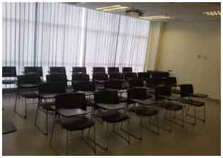 | |
| Fig. 2: | Seminar room as load of case study |
 | |
| Fig. 3: | Schematic of solar desiccant cooling in ventilation mode |
Temperature, humidity ratio and air flow rate are considered to measurement. Regarding to measurement results, the cooling load, cooling coil capacity of FCU and air properties in different point of FCU are detected. In the third step, a FCU standard is designed based on standard indoor condition. In the last step, result of FCU standard and case study FCU are compared.
Case study description: A FCU installed in a seminar room is selected as case study for energy audit purpose. In other word, the case study is including a FCU system which used as air-condition system for a seminar room. In general, an AC system can be reasonably evaluated when this system acts under a load; this evaluation becomes possible because AC systems are designed to remove sensible heat and latent heat in a room to reach a comfortable condition.
Therefore, investigation of room conditions and cooling load is the first step to determine the required capacity of an AC system. The inner view of the seminar room as case study is illustrated in Fig. 2.
| Table 1: | Specification of room |
 | |
| L: Length, W: Width and dTh: Thickness | |
In each zone, the total cooling load, which includes latent and sensible loads, depends on heat gain of a particular building. The heat gain of a building can be categorized as external and internal heat gain, which are explained in the following sections:
| • | External heat gain: This kind of heat gain is related external factors such as infiltration, solar radiation, conduction from wall, ceiling, roof and window |
| • | Internal heat gain: This type of heat gain is related to internal factors such as people, lighting, equipment, which produced the heat inside the room |
Latent and sensible loads are increased by people and by infiltration. Solar radiation, wall and window conduction and equipment increase sensible load.
The seminar room is located at the 5th floor of the one building in University Kembangsaan Malaysia (UKM) and covers an area of 24 m2. This room is used for seminars and academic classes for a maximum of 30 people. Figure 3 shows the schematic of the case study room (highlighted).
The room is surrounded by two external walls (A and D) and two internal walls (B and C). Walls A, B, C and D are oriented SE, NE, NW and SW, respectively. Wall A is located in front of the staircase, windows span 95% of the area of wall D. The two entrance doors of the room are located on wall B (corridor wall). Wall C is the common wall between the studied room and the adjacent room. Orientation, type and dimension of walls, windows and doors of the room significantly affect the cooling load as heat gain, thus, the details of these parameters are explained in Table 1.
The walls are 15 cm in thickness and composed of brick and cement plaster materials. Existing appliances in the room are also identified to calculate cooling load. A total of 14 lamps (40 W) and one data projector (120 W) are also found in the room. An FCU is a device equipped with a blower, a filter and a cooling/heating coil. This device is used to supply air. The FCUs are usually installed in rooms. In this study, the studied FCU is installed on the ceiling of the seminar room.
| Table 2: | FCU specification model |
 | |
The main energy-consuming components of a FCU are the fan, the pump and the chiller. Specification of FCU is shown in Table 2.
Case study measurement: To realize the quantity of cooling load, cooling coil capacity and indoor thermal condition of seminar room, temperature and humidity transmitter have been installed in different parts of FCU and seminar room. Temperature, humidity and flow rate of air in 5 points of FCU were considered as measurement parameters. As shown in Fig. 4 the 4 points are consist of supply air, return air, fresh air (outdoor air) and mix air.
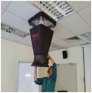
Six diffusers are installed on the ceiling to supply air from the main duct to the inner part of the room. The air flow rate of supply air is the sum of the air flow rates of the six diffusers. Therefore, the air flow rates of six diffusers are measured to measure the flow rate of supply air as shown in Fig. 5.
A general view of temperature and humidity measurement is shown in Fig. 6.
Calculation of FCU standard: The FCU that can achieve standard indoor condition in the seminar room is called "Standard FCU." According to the ASHRAE standard for air-conditioning systems, the air properties and capacity of a cooling system can be determined based on three parameters of cooling load, indoor and outdoor conditions as shown in the following:
| • | Indoor condition design: 25°C, 50% RH, |
| • | Outdoor condition design: 30°C, 80% RH, |
| • | The sensible load: 1.3 t, latent load: 1.36 t |
To design of FCU standard, the supply air temperature and humidity can be determine by Eq. 1 and 2:
| (1) |
where, Qsl (kW) is sensible load, m (m3 sec–1) is air flow rate, T1 (°C) is temperature of supply air and T2 (°C) is temperature of return air (room air):
| (2) |
 | |
| Fig. 4: | Schematic of case study measurement points |
 | |
| Fig. 5: | Air flow rate measurement |
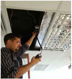 | |
| Fig. 6: | Temperature and humidity measurement of supply air in main duct of FCU |
where, Qll (kW) is latent load, m is air flow rat, HR1 (kg kg–1) is humidity ratio of supply air and HR2 (kg kg–1) is humidity ratio of return air (room air).
Compassion between case study FCU and FCU standard: To evaluation of the case study, the measurement result should be compare with FCU standard. Indoor thermal condition of seminar room under two mentioned FCU can be compare.
RESULTS AND DISCUSSION
The results of this study can be categorized to three parts of measurement result, calculation result and comparison results which are explained in following sections. By result of measurements, three factors of cooling load, cooling coil capacity and indoor air properties have been analyzed in the first three following sections. Result of FCU standard have been found by calculation. The comparison between FCU standard and case study FCU are presented.
Cooling load of case study: In general, cooling load calculation is the initial phase of the design for cooling systems, which directly influences the thermal comfort condition, energy efficiency and indoor air quality of buildings. The size of cooling systems should be selected based on cooling load amount. Otherwise, a small cooling system cannot achieve thermal comfort conditions but a large cooling system can cause problems such as over cooling and high energy consumption. The cooling load includes two kinds of sensible and latent heat that must be removed from a room via a cooling system. Table 3 shows the load calculation details in the seminar room.
In this study, the apportioning of latent and sensible loads has been highlighted through the calculation and measurement results. The calculation of cooling load indicates the effect of the amount of external and internal heat gains on cooling load (sensible and latent), whereas the measured cooling load reflects the distribution modality of sensible and latent loads during that time. To evaluate seminar room load, all load factors that affect cooling load are considered.
To identify the extent of the effect of external and internal load factors on each load type, the sensible and latent loads of each factor are calculated separately. Total sensible load is 1.30 t and total latent load is 1.37 t. Infiltrations from the door and the windows have maximum effect on the amount of latent load, whereas solar gain from the windows has maximum effect on the amount of sensible load. Total load-cooling load is 2.677 t.
Figure 7 shows the cooling load measurement results in the seminar room for one day of office time (8 am to 6 pm on 12th April, 2014). The general view of the cooling load distribution versus time indicates that the latent load of the room is greater than the sensible load. The results show that the amounts of sensible and latent loads every 20 min are between 4 and 5 kW.
Figure 8 shows an apportioning of cooling load in the seminar room, which is the average of one month of measurements (April, 2014). The percentage of sensible load is 49% and that of latent load is 51%. Therefore, the SHR of the seminar room is 0.49. The average amounts of sensible, latent and total loads are 4.59, 4.77 and 9.36 kW, respectively.
Cooling coil capacity: The process of removing latent load is dehumidification and that of removing sensible load is sensible cooling. The cooling capacity measures the capability of a cooling system to remove heat. Therefore, the amount of sensible and latent heat removed in the cooling coil of FCU can be regarded as the sensible and latent capacities of FCU, respectively.
| Table 3: | Detail of cooling load of seminar room |
 | |
 | |
| Fig. 7: | Cooling load profile of seminar room during one day |
 | |
| Fig. 8: | Apportioning of cooling load of seminar room |
 | |
| Fig. 9: | Distribution of cooling coil capacity during the one day |
Figure 9 shows the sensible, latent and total capacities of FCU for one day (8 am to 6 pm). The distribution of FCU capacity versus time indicates that latent capacity is higher than sensible capacity. The amounts of latent and sensible capacities are between 4 and 5 kw, whereas total capacity is approximately 11 kW.
Figure 10 shows the apportioning cooling coil capacity demonstrates that 56% of the total capacity is used for dehumidification, whereas, 44% of is used for sensible cooling. In conclusion, 56% of the energy used in the cooling coil from the chiller is for mechanical dehumidification. Therefore, 56% of FCU capacity can be saved if chemical dehumidification is used instead of mechanical dehumidification.
Air properties in different points of FCU: Based on the boundary of the case study, the air properties of four FCU points are measured during one day of FCU operation from 8 am to 6 pm. The four points include the seminar room, mixed air (before the cooling coil), supplied air (after the cooling coil) and fresh air (outdoor). Figure 11 shows the temperature (°C) of these points versus time (h). The highest temperature is related to the outdoor temperature of Malaysia.
The uptrend line is related to the increase in outdoor temperature, whereas the downtrend lines indicate a reduction in temperature during that time. Outdoor temperature ranges from 20-38°C. The lowest temperature is related to supplied air. The temperature of the supplied air indicates the air temperature after the cooling coil, which ranges from 15-20°C. The temperature in the seminar room is nearly constant at approximately 25°C. Mixed air temperature is higher than the temperature in the room because the latter is mixed with outdoor air.
Figure 12 shows the humidity ratios of the different FCU points. The behavior of the humidity ratio of these points is similar to the behavior of temperature. Hence, the humidity ratio of outdoor air is the highest, whereas, that of supplied air is the lowest. The humidity ratio in the room is more than that of the supplied air and the humidity of mixed air is more than that in the room.
Regarding the reduction of the humidity ratio of the air in the cooling coil, the air after the cooling coil has the lowest humidity ratio. The indoor thermal condition in the room is evaluated by measuring the temperature, humidity and flow rate of the air in specific points of the case study. The air properties of outdoor, mixed, supplied and room (return) airs are indicated by the numbers 1, 2, 3 and 4, respectively. Result of measurement shows that the average air flow rate of specific points from 1-4 are 240, 1200, 1200 and 960 CFM, respectively. The temperature and humidity ratio of supplied air (point 3) are 17.8°C and 92.9%, respectively, whereas those of room air (point 4) are 24.3°C and 77.2% respectively.
According to the ASHRAE comfort condition, indoor condition designs should consist of a temperature of 25°C, a relative humidity of 50% and a humidity ratio of 0.0098 kg kg–1. Therefore, the seminar room cannot attain thermal comfort under FCU because the relative humidity in the room (77.2%) is higher than 50%. Figure 13 shows a psychometric diagram of FCU, which demonstrates air behavior in different FCU points and the room.
To increase IAQ in the aforementioned FCU, return air is mixed with outdoor air in point 2, which increases the temperature and humidity of air before the cooling coil (mixed air).
 | |
| Fig. 10: | Apportioning of cooling coil capacity |
 | |
| Fig. 11: | Temperatures of different points of case study during the working hours |
 | |
| Fig. 12: | Humidity ratio of different points of case study during the working hours |
 | |
| Fig. 13: | Psychometric chart of FCU |
The cooling coil produces supplied air by reducing the temperature and humidity of mixed air.
Moreover, the sensible cooling and dehumidification processes in the cooling coil (2-3) reduce the temperature and humidity ratio of air from 25.9-17.8°C and from 0.0163-0.0119 kg kg–1, respectively. Supplied air enters the room to remove both sensible and latent heat from it (3-4). The temperature and humidity of the room then reach up to 24.3°C and 77.2, respectively, which are not in the range of thermal comfort conditions. The humidity of room air actually depends on supplied air humidity and supplied air humidity depends on the dehumidification process in the cooling coil. Therefore, the main reason for high room humidity is related to the low dehumidification capacity of the cooling coil, which cannot produce a suitable amount of supplied air.
To achieve thermal comfort conditions, a suitable amount of supplied air should have a temperature of 18.3°C and a humidity ratio of 0.007 kg kg–1. Two methods can produce a suitable amount of supplied air, namely: (a) Increasing the capacity of the mechanical dehumidification process in the cooling coil and (b) Using a chemical dehumidification process. For the first method, the dehumidification and sensible cooling processes in the cooling coil cannot be controlled separately.
To increase the dehumidification capacity, the capacity of the cooling coil should be increased to augment sensible cooling unexpectedly. Hence, reheating is required to reduce sensible cooling. In the second method, a desiccant wheel can be used, which can reduce humidity ratio.
Results of FCU standard: Results of the calculations for air properties at different points of FCU standard have been detected. To identify dehumidification and cooling processes in FCU, the points are illustrated through a psychometric chart in Fig. 14. The 4 points, namely, supplied, mixed, fresh and room air are drawn in the psychrometric chart of FCU standard.
| Table 4: | Air properties of case study FCU and standard FCU |
 | |
 | |
| Fig. 14: | Psychometric chart of FCU standard |
 | |
| Fig. 15: | Indoor condition under case study FCU and FCU standard |
Fresh air (point 1), which comprises 20% of the total airflow rate is mixed with 80% return air (point 2) at point 3. Mixed air should then be cooled and dehumidified to obtain the required condition of supplied air. Based on the results, the humidity of mixed air should be reduced from 0.019-0.007 kg kg–1 and the temperature should be decreased from 26-18.3°C to achieve the designed indoor condition.
No cooling coil can reduce humidity and sensible cooling from points 3-5 because the mixed air point has a high humidity. However, the 3-5 coil process is impossible because this line does not intersect the saturation curve. Therefore, the line of 3-4 is selected as the coil line process that intersects the saturation curve. The 3-4 process can reduce the humidity of mixed air to reach a desirable humidity of supplied air but temperature is suddenly reduced to 10.3°C, which is more than the desirable temperature of supplied air.
This phenomenon occurred in the cooling coil because dehumidification and sensible cooling work together in this component. This event indicates that air at point 5 has a suitable humidity and an unsuitable temperature (very cold) for supplied air. Meanwhile, air temperature is reduced to more than the required temperature to achieve the desirable humidity for supplied air through the cooling coil. Therefore, air should be heated from 10.3-18.3°C by the reheating process of 4-5 to reach the desirable temperature.
Comparison results of case study FCU and FCU standard: Table 4 presents the comparison between the air properties of the case study FCU and standard FCU. The results of standard FCU show that with regard to the high latent load of the room, reheating must be conducted after the cooling coil process to achieve thermal comfort condition. In the case study FCU, reheating is not conducted to reduce energy consumption. Therefore, the thermal comfort condition of the room is not achieved.
Figure 15 shows seminar room condition under application of case study FCU and FCU standard. The Temperature and humidity of seminar room air under case study FCU are 24.3°C and 77.2%, respectively. According to the ASHRAE comfort condition, indoor condition designs should consist of a temperature of 25°C, a relative humidity of 50% and a humidity ratio of 0.0098 kg kg–1. Therefore, the seminar room cannot attain thermal comfort under FCU because the relative humidity in the room (77.1%) is higher than 50%. The results of standard FCU show that with regard to the high latent load of the room, reheating must be conducted after the cooling coil process to achieve thermal comfort condition. In the case study FCU, reheating is not conducted to reduce energy consumption. Therefore, the thermal comfort condition of the room is not achieved.
The comparison between the energy consumption of the case study FCU and standard FCU based on the ASHRAE standard for one month of office hours is shown in Table 5.
The total energy consumption of standard FCU is higher than that of the case study FCU. Consequently, the case study FCU cannot achieve the thermal comfort condition but standard FCU realize this condition.
| Table 5: | Monthly energy consumption of case study FCU and standard FCU |
 | |
CONCLUSION
This study presents evaluation of conventional cooling system in term of cooling load, cooling coil capacity and indoor thermal condition in hot humid region of Malaysia. An installed FCU in one seminar room have been measured as case study. Results of measurements have been compared with a standard FCU which was designed based on ASHRAE standard. The FCU evaluation achievements are explained as following:
| • | The measurement result demonstrates that the total cooling load of the room is 9.36 kW, 51% of which is related to latent load and 49% to sensible load. The latent load of the seminar room is higher than its sensible load in the hot and humid regions of Malaysia |
| • | The measurement results demonstrate that the average values of the dehumidification, sensible cooling and total cooling capacities of the cooling coil of FCU are 7.28, 5.78, and 13.06 kW, respectively. Therefore, 56% of the total cooling coil capacity is related to the dehumidification process and 46% is related to the sensible cooling process. That is, the portion of dehumidification capacity is higher than that of sensible cooling capacity in the cooling coil of FCU |
| • | The measurement result demonstrates that by using FCU in the seminar room, the temperature and relative humidity of the room reach 24.2°C and 77%, respectively. Therefore, FCU cannot produce the suitable amount of supplied air to achieve standard indoor condition in the seminar room |
| • | To achieve suitable indoor conditions, an FCU standard is designed. The result demonstrates that the energy consumption of the FCU standard is 123 kWh, whereas that of the case study FCU is 90 kWh. To achieve standard indoor thermal condition by using the conventional cooling system, the capacity of the cooling coil should be increased to 3 kW and reheating is required after passing through the cooling coil. Therefore, the energy consumption of the FCU standard is 1.4 times higher than that of the installed FCU |
ACKNOWLEDGMENTS
The authors would like to thank the Institute of Product Design and Manufacturing (IPROM) in Universiti Kuala Lumpur, for providing the laboratory facilities and technical support.
REFERENCES
- La, D., Y.J. Dai, Y. Li, R.Z. Wang and T.S. Ge, 2010. Technical development of rotary desiccant dehumidification and air conditioning: A review. Renew. Sustain. Energy Rev., 14: 130-147.
CrossRefDirect Link - Dezfouli, M.S., Z. Hashim, M.H. Ruslan, B. Bakhtyar and K. Sopian et al., 2012. Experimental investigation of solar hybrid desiccant cooling system in hot and humid weather of Malaysia. Proceedings of the 10th WSEAS International Conference on Environment, Ecosystems and Development, December 29-31, 2012, Montreux, Switzerland, pp: 172-176.
- Henning, H.M., 2007. Solar assisted air conditioning of buildings-an overview. Applied Thermal Eng., 27: 1734-1749.
CrossRefDirect Link - Dezfouli, M.M.S., S. Moghimi, F. Azizpour, S. Mat and K. Sopian, 2014. Feasibility of saving energy by using VSD in HVAC system, a case study of large scale hospital in Malaysia. WSEAS Trans. Environ. Dev., 10: 15-25.
Direct Link - Fong, K.F., V.I. Hanby and T.T. Chow, 2006. HVAC system optimization for energy management by evolutionary programming. Energy Build., 38: 220-231.
CrossRefDirect Link - Dezfouli, M.M.S., S. Mat, K.S.M. Sahari, K. Sopian and M.H. Ruslan, 2014. Application of solar air-condition system to prevent wall condensation and sick building syndrome in humid area. Proceedings of the 12th International Conference on Computer Applications in Environmental Sciences and Renewable Energy, April 23-25, 2014, Kuala Lumpur, Malaysia, pp: 225-229.
Direct Link