
Yi Liu
Department of Engineering Science, University of Oxford, Oxford OX2 6PE, United Kingdom
Journal of Applied Sciences
Year: 2006 | Volume: 6 | Issue: 4 | Page No.: 767-774


ABSTRACT
The interaction of a shock wave and boundary layer in a highly loaded blade often leads to extremely complicated flow phenomena. This is especially true when operated in the off-design conditions. In this study, a modified implicit flux-vector-splitting solver of the Navier-stokes equations is extended to numerically study the performance of such transonic cascade flow under design and off-design conditions. A compressible low Reynolds number k-ε turbulence model and a transition model are integrated into the numerical code in order to predict the boundary layer and its interaction with the shock accurately. The aerodynamic performance of prototype highly loaded blade is investigated through a serious of numerical studies. Numerical results are presented and discussed.
PDF Abstract XML References Citation
How to cite this article
Yi Liu, 2006. Aerodynamic Performance of Off-design Highly Laded Blade: A Case Study. Journal of Applied Sciences, 6: 767-774.
DOI: 10.3923/jas.2006.767.774
URL: https://scialert.net/abstract/?doi=jas.2006.767.774
DOI: 10.3923/jas.2006.767.774
URL: https://scialert.net/abstract/?doi=jas.2006.767.774
INTRODUCTION
Recently efforts have been directed towards to design blades with increasing aerodynamic loading (Curtis et al., 1996; Howell et al., 2000; Sarkar, 2005). The large pressure ratio and a high loading coefficient in such turbine blades could cause a complicated transonic flow pattern with shock waves and separated zones, especially when operated under the off-design conditions.
A highly loaded blade has been actively studied (Granovskii, 1995; Curtis et al., 1996; Gehrer and Jericha, 1998; Howell et al., 2000; Segawa, 2001; Sarkar, 2005). The work, for example, has been focused on design for the single-stage transport and industrial turbines (Granovskii, 1995; Segawa, 2001). The aerodynamic efficiency and the loading coefficient of such blades need to be carefully optimized. If no separation occurs on the blade surface and the blade aerodynamic loading distribution is properly controlled, a highly loaded blade can offer higher efficiency and lower cost compared with a conventional blade. On the other hand, if separation does occur, their performance can be (far) worse than that of conventional blades.
To design and analyse such highly loaded turbine blades, reliable computational methods are essential. Accurate prediction of wake mixture, shock and interactions with boundary layer is so crucial to the design and evaluation of highly loaded blades. The main challenge here is to accurately predict the main flow features while maintaining a high efficiency.
In this study, we attempt to numerically investigate the aerodynamic performance of a prototype highly loaded blade. The modified implicit flux-vector-splitting code (MIFVS) has been developed and applied to many flow problems (Liu, 1996; Liu et al., 1996; 1997; 2002; 2005). The objective of this study is to extend the MIFVS solver to the transonic cascade flow in the highly loaded turbine blade. Prototype of highly loaded transonic blade is therefore calculated with confidence. Subsequently, the effects of incidence angle on the aerodynamic performance of the highly loaded turbine blade are explored. Finally, we draw the main conclusions.
MATERIALS AND METHODS
Prototype of highly loaded turbine blade is proposed and calculated in University of Oxford, as a part of the author’s long term research interest.
Here, the geometry of prototype blade, the design condition and the numerical methods are presented.
Prototype of highly loaded turbine blade: The geometrical characteristics of prototype highly loaded turbine blade are summarized in Table 1 and Fig. 1. This is designed for a highly loaded single stage rotor blade, with a large turning angle of 130°. The blunt leading edge and small curvature of the pressure surface aim to offer a better off-design operation performance.
The design condition: The design conditions correspond to an isentropic exit Mach number of M2,is = 1.25, Reynolds number of Re2 = 6x10⁵ and a free-stream turbulence intensity of Tu = 5%. The inlet flow angle is 60°.
Numerical approach: An efficient numerical method, based on a Modified Implicit Flux Vector Splitting (MIFVS) solver for Reynolds averaged Navier-stokes equations (RANS), has been developed and successfully applied to many different cases (Liu, 1996; Liu et al., 1996; 1997; 2002; 2005).
| Table 1: | Parameters of prototype highly loaded turbine blade |
 | |
Importantly, this numerical code has been the establishment of an implicit difference scheme and eigenvalue analysis of the matrix for the Navier-Stokes equations. Compared to conventional implicit methods, the MIFVS is a Jacobian spectral radius scheme and a non-approximate-factorization scheme. Since matrix operation is not needed, the amount of computing work in each time step can be significantly reduced. It has been demonstrated that the MIFVS implicit formulation is adequately efficient when applied to FVS methods, while maintaining a high level of accuracy and robustness.
A compressible low Reynolds number k-ε model has been implemented into the MIFVS code to simulate the turbulence boundary layer and interaction with shock waves (Liu, 2003). Since transition to turbulence and re-laminarization may both occur in turbine cascade flows and are strongly affected by large pressure gradients, positive and/or negative. Transition is normally of the by-pass type, which is induced by the incoming free-stream turbulence, or triggered by a local flow separation or a shock. Transition model is embodied in the low Reynolds number k-ε turbulent model by modifying the dumping function.
The numerical approach described here has been validated through collective comparisons with the experimental data and other published simulation results against VKI highly loaded turbine vane (Liu, 2003). Now we can apply the MIFVS code to modelling the prototype highly loaded turbine blade.
RESULTS AND DISCUSSION
Computational domain and grid: Figure 1 shows the computational domain and grid, with the boundary conditions marked. Considered the flow complexity near the blunt leading and trailing edges, the periodic boundaries are sketched such as to achieve a better resolution. Shown is a typical periodic H-type cascade grid (every other point along each direction), in which the blade is embodied in the computational domain. The periodic boundary is preserved by the nodal periodic distributions.
A specific distribution along pitch direction, as shown in Fig. 1, the smoother combination of linear and logarithm functions, is accomplished to refine the mesh near the wall to improve boundary layer resolution. The first grid point away from the blade is place at y+ of about 1, with approximately 20 points within the boundary layer. The nodal distributions are gradually relaxed towards inlet and outlet boundaries. It is worthwhile to mention that the grid has been improved the smoothness and orthogonality by solving the Poisson equations using initial grid generated algebraically.
Results shown here are obtained with 26000 cells (200x130). Experience with the VKI highly load turbine vane simulations enables us to conduct the numerical simulations confidently (Liu, 2003).
The flow field of the design condition: Figure 2 plots the isentropic Mach number (a) and non-dimensional static pressure (b) distributions on both the pressure and suction surfaces of the blade. The incidence angles, I, correspond to different inlet flow angles. The abscissa is the arc length S from the leading edge along the blade surface.
For the design condition of the highly loaded turbine blade, a smaller pressure difference between the pressure and suction side (on the leading part of the blade surface) helps to reduce the secondary flow loss (Fig. 2b). The flow is observed to steeply accelerate along the suction side up to 8 mm. Then a weak recompression is followed by a rather flat Mach number distribution (until to 40 mm) and subsequently by another one rapid re-acceleration. Two adverse pressure gradients starting from approximately 80 mm indicate that strong shock wave take place. The velocity distribution along the pressure surface varies smoothly downstream of the leading edge.
We shall discuss the effect of incidence angle on aerodynamics in the off-design condition section.
Figure 3 presents the computed total pressure profiles at locations of 20 and 60% Chord downstream of the trailing edge. The drop of the total pressure indicates the total blade profile loss, including blade surface loss, shock loss and wake loss.
It is clearly seen that the flow is decelerated by an internal shock wave. A strong external shock is generated at the rear suction side of the blade. This external shock wave is interacted with the boundary layer and causes the flow separated locally outside the passage.
To provide the baseline of flow characteristics in a highly loaded turbine blade cascade, in addition to Fig. 4, we plot the velocity vectors in the areas of interest for the design condition in Fig. 5. As expected, the flow is accelerated along the cascade passage.
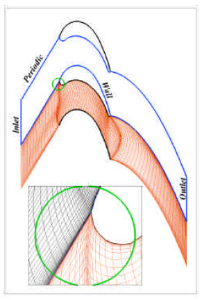 | |
| Fig. 1: | Computational domain and grid |
 | |
| Fig. 2: | The surface profiles of the isentropic Mach number (a) and non-dimensional static pressure (b) |
 | |
| Fig. 3: | The wake profiles of the total pressure at the 20% (a) and 60% (b) of the Chord downstream of the trailing edge |
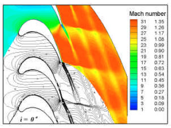 | |
| Fig. 4: | The contour plots of Mach number for the design operation condition |
 | |
| Fig. 5: | The velocity vectors for the design operation condition at regions of the leading and trailing edge of interest |
 | |
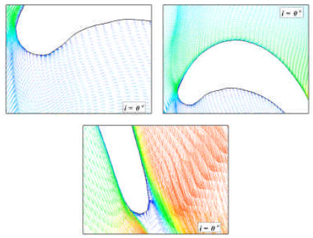
| Fig. 6: | The contour plots of Mach number for the +10° (a) and -10° (b) incidence angles |
 | |
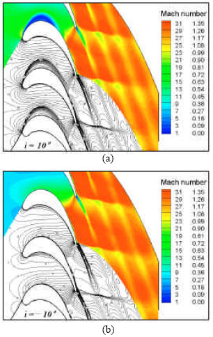
| Fig. 7: | The velocity vectors for the +10° incidence angle condition |
 | |
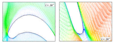
| Fig. 8: | The velocity vectors for the -10° incidence angle condition |
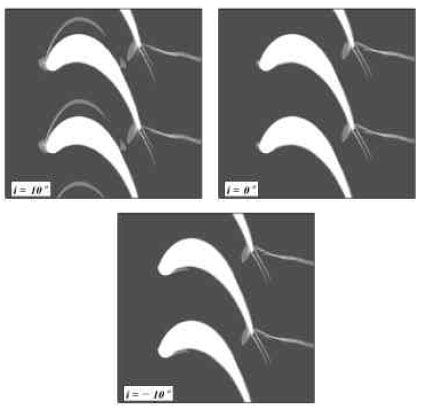 | |
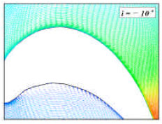
| Fig. 9: | The simulated contours of density gradient magnitude (numerical Schlieren), at the incidence angles of +10°, 0° and -10° |
The boundary layer remains attached in most parts of the blade surface. The small separation bubble appears on the suction side just before the trailing edge, as we discovered in the Mach number contours (Fig. 4). A pair of vortexes are formed downstream of the trailing edge.
The flow field of the off-design conditions: Figure 2 also plots the isentropic Mach number distribution for incidence angles of +10° and -10°.
There is sharp increase at the suction side for +10° incidence angle case. The Mach number reaches about 1.2 in a very short distance. An internal shock wave is generated and decreases the flow velocity. From a location of about 50 mm, the Mach number distribution follows the almost same trend as one for the design condition. The Mach number along the pressure surface exhibits smoother variations, with the overall level higher than that for the design condition.
For an incidence angle of -10° case, compared with the design case, the almost identical Mach number profiles on the pressure side are found. On the suction side, instead of the flat Mach number distribution, there is a slow acceleration to match the Mach number at a location of about 50 mm as result of a lower acceleration of the leading edge.
In general, the isentropic Mach number profiles indicate the blade is more sensitive to a positive incidence angle. This will further be illustrated by the Mach number contours and velocity vectors.
Note that apart from the significant increase in the blade loss, at +10° incidence angle case, smaller pressure difference between the pressure and suction surfaces indicates the decrease in the aerodynamic loading, too.
The contour plots of Mach number for incidence angles of +10° and -10° are shown in Fig. 6, respectively. In contrast to the design inflow angle, the flow accelerates sharply over a short distance of the leading edge on the surface under the incidence angle of +10°, as seen in Fig. 2. Then the flow is decelerated by an internal strong shock wave. As a consequence of shock-boundary layer interaction, the flow separates on the front suction side (Fig. 6a). Therefore, the rather serious separation deteriorates the performance of this highly loaded blade and increases its total pressure loss, as shown in Fig. 3.
The Mach number contours for the incidence angle of -10°, shown in Fig. 6b, further verify the finding from the Mach number profiles of Fig. 2, with an almost same flow pattern as the design condition.
Figure 7 presents the velocity vectors for the incidence angle of +10°. A large separation zone is clearly seen from the right beginning of the suction side. The velocity vectors in the rear part of the blade are almost the same as that in the design condition.
In contrast, for the incidence angle of -10° condition shown in Fig. 8, a relatively small separation bubble is observed in the front curved part of the pressure side. The flow is fully attached to the suction side and accelerated in the passage of the blades.
Finally, we produce numerical Schlieren images for all three cases. This is achieved by flooding the density gradient magnitude contours shown in Fig. 9. As common features, a strong shock wave is observed at the rear suction side of blade and a weak trailing edge shock is generated on the pressure surface, too.
A large separation bubble is found at the front part of the suction side at for the incidence angle of +10° case. On the other hand, only a small separation zone along the pressure surface is visible at negative incidence angle.
CONCLUSIONS
An efficient numerical method, MIFVS, has been extended to solve the transonic cascade flow in the prototype highly loaded turbine blades. It has been demonstrated to be numerically stable and efficient for solving such transonic cascade flows. The main flow features are well predicted. Results obtained for the surface isentropic Mach number and pressure profiles, the wake properties, the contour plots, the velocity vectors and the numerical Schlieren images provide us the detailed information.
This code has been further applied to model cascade flow of highly loaded turbine blades at positive and negative incidence angle of -10° and +10o operating conditions, respectively. We have shown that the aerodynamic performance of the prototype highly loaded blade detrimentally effect the flow field with a significant separation zone on the front of the suction side when operating at an incidence angle of +10°.
ACKNOWLEDGMENTS
Professor Jung Y. Yoo, Seoul National University, South Korea and Professor Peter R. Voke, University of Surrey, United Kingdom, are acknowledged for their assistance.
REFERENCES
- Gehrer, A. and H. Jericha, 1998. External heat transfer predictions in a highly-loaded transonic linear turbine guide vane cascade using an upwind biased Navier-stokes solver. J. Turbomachinery, 121: 525-531.
Direct Link - Howell, R.J., O.N. Ramesh, H.P. Hodson, N.W. Harvey and V. Schulte, 2000. High loaded and aft loaded profiles for low pressure turbines. J. Turbomachinery, 123: 181-188.
Direct Link - Liu, Y., B. Liu and Y.M. Xiang, 1996. A new highly efficient and accurate implicit flux vector splitting schemes. Chinese Sci. Bull., 41: 1229-1232.
Direct Link - Liu, Y. and B.J. Bellhouse, 2005. Prediction of jet flows in the supersonic nozzle and diffuser. Int. J. Numer. Methods Fluids, 47: 1147-1155.
Direct Link