
A.K.M. Mohiuddin
Not Available
Mohd Rashidin Ideres
Not Available
Shukri Mohd Hashim
Not Available
Journal of Applied Sciences
Year: 2005 | Volume: 5 | Issue: 7 | Page No.: 1292-1298


ABSTRACT
The main objective of this study was to find the relationship between the back pressure and the noise level. Back pressure needs to be kept to a minimum. The relationship between the noise and the back pressure is inversely proportional; lowering the noise level at the tip will result in high back pressure. However, this relationship is undesirable as the requirement is to have a quiet muffler with a small back pressure (ideal muffler). The design of the muffler chamber separation and arrangement is essential in determining the muffler characteristics. Some design considerations are proposed in order to come up with an optimum muffler design. The result shows a general shape of an average design of the muffler which would be the most suitable for the test car model.
PDF Abstract XML References Citation
How to cite this article
A.K.M. Mohiuddin, Mohd Rashidin Ideres and Shukri Mohd Hashim, 2005. Experimental Study of Noise and Back Pressure for Silencer Design Characteristics. Journal of Applied Sciences, 5: 1292-1298.
DOI: 10.3923/jas.2005.1292.1298
URL: https://scialert.net/abstract/?doi=jas.2005.1292.1298
DOI: 10.3923/jas.2005.1292.1298
URL: https://scialert.net/abstract/?doi=jas.2005.1292.1298
INTRODUCTION
In an automobile, the exhaust system carries exhaust gases from the engine’s combustion chamber to the atmosphere. Exhaust noise of internal combustion engines is known to be the biggest pollutant of the present-day urban environment. Fortunately, however, this noise can be reduced sufficiently by means of a well-designed muffler which is also known as silencer. Exhaust gases leave the engine in a pipe, traveling through exhaust manifold, catalytic converter and a muffler before exiting through the tailpipe. There are various design that are available today, in which the only difference is the way they handle the amount of gasses released through the exhaust manifold. Back pressure represents the extra static pressure exerted by the muffler on the engine through restrictions in the flow of exhaust gases. Unlike back pressure, noise has to be considered for its effect towards the environment.
The conventional muffler is an enclosed metal tube packed with sound-deadening material. An exhaust muffler is an acoustic filter except that waves are convected downstream by the moving medium. Inside a muffler, it contains a deceptively simple set of tubes with some holes in them. These tubes and chambers are actually designed to reflect the sound waves produced by the engine in such a way that they partially cancel themselves out. Most conventional mufflers are round or oval-shaped with an inlet and outlet pipe[1]. Some mufflers contain partitions to help reduce noise.
Generally an exhaust muffler should satisfy some basic requirements such as adequate insertion loss, low back pressure, ideal muffler sizing which could effect the cost and accommodation and the last one could be the durability to withstand rough conditions and extremely high temperatures. Hence some design considerations have to be taken in order to come up with an optimum muffler design.
The parameters that govern the performance of the muffler are the muffler chamber design, restrictions of the flow of the exhaust gasses and the material of the muffler itself. The relationship between the noise and the back pressure is inversely proportional; lowering the noise level at the tip will result in high back pressure.
One type of muffler design uses only absorption of the sound wave to reduce the noise level without messing with the exhaust gas pressure. It is known as glass pack muffler and it reduces backpressure but also producing higher noise level compared to the factory standard muffler. Hence, the sound produced by this type of muffler is much higher compared to the other type of mufflers.
Another type of muffler known as reflective muffler incorporates a chamber called the resonance chamber, which uses the superposition method to cancel out the sound wave reflected to the wall of the chamber. The restriction of this muffler is the size of the resonance chamber and also the diameter of the muffler. In addition to these types of mufflers, there is another muffler which is currently under research all over the world. This muffler is called active noise canceling muffler, which uses data from the engine’s ECU to produce active noise canceling inside the muffler.
Aeroacoustic of exhaust muffler: Acoustic filters are a medium placed between a source of acoustic signal and the receiver. It consists of a set of elements which is analogous to the electrical filters or vibration isolator. An exhaust muffler is an acoustic filter except that waves are convected downstream by the moving medium, which is mean flow. Thus, exhaust muffler is classified as aeroacoustic filters. The difference between aeroacoustic and acoustic filters is that the aeroacoustic filters requires a medium, such as mean flow to transmit the waves from a point to another[2].
Sound waves: Sound is a pressure wave formed from pulses of alternating high and low air pressure. In an engine, pulses are created when an exhaust valve opens and a burst of high-pressure gas suddenly enters the exhaust system. The molecules in the gas collide with the lower-pressure molecules in the pipe, causing them to stack up on each other. They in turn stack up on the molecules a little further down the pipe, leaving an area of low pressure behind. In this way, the sound wave makes its way down the pipe much faster than the actual gases do. When these pressure pulses reach our ears, the eardrum vibrates back and forth which will be interpreted as sound.
The wave's amplitude determines how loud the sound is. Sound waves with greater amplitudes move our eardrums more and this sensation is registered as a higher volume. To cancel out sound, it is possible to produce a sound wave that is exactly the opposite of another wave.
The design of a resonance chamber inside a muffler reflects the sound wave which is 180 degrees out of phase with the engine noise. The sound waves reflected from the wall collide with the exhaust sound waves and they cancel each other out, leaving only low-level heat to emerge from the tailpipe. The resonance chamber in the muffler reflects the sound wave from the engine as it hits the resonance chamber wall. As a result, destructive and constructive waves are formed inside the chamber with only a small fraction of the sound wave is released back to the atmosphere. The chamber length is carefully calculated to accommodate the average sound pressure level created by the engine.
The exhaust pulses are created when each cylinder in the engine is encountering an exhaust stroke, which is greatly dependant on the firing order of the engine. The more cylinders the engine has the closer the pulses are created and more sound is produced.
Back pressure: The average pressure in the exhaust pipe during the exhaust stroke is called the mean exhaust pressure and the atmospheric pressure is called the ambient pressure. The difference between these two pressures is defined as back pressure[3].
The exhaust valve opens a few degrees before the piston reaches the BDC during the expansion stroke and closes a few degrees after the piston reaches the TDC. The burned-out gasses are exhausted only during about one-third of the total cycle time. Therefore, the rest of the time, the exhaust pipe has a closed end termination on the engine side and has the muffler and the atmospheric termination at the other end, by which the mean exhaust pressure moves up and down, creating exhaust pulses with a frequency in accordance with the number of cycles completed in a second. This frequency is called the firing frequency and it is dependent on the number of cylinders of the engine and the firing order of the cylinders.
The higher the back pressure created by the exhaust system, the less is the net power available on the crankshaft and hence the more is the specific fuel consumption. The amount of power loss depends on many factors, but a good rule-of-thumb is that one inch (25.4 mm) of mercury backpressure causes about 1.0% loss of maximum engine power[4].
Exhaust noise: Unlike backpressure, noise has to be considered for its effect towards the environment. For that reason some rules and standard must be established as the guideline to ensure the environmental safety. A lot of research works have been done by different organizations regarding the noise rules and standard. Few of them are:
| • | Rules of the Environment Protection Commission of Hillsborough County[5]. |
| • | Road Traffic (Vehicle Standards) Rules 1999-South Australia[6]. |
| • | Occupational Safety and Health Act (OSHA). |
Noise causes hearing loss, interferes with human activities at home and work and in various ways injurious to people’s health and well-being.
MUFFLER DESIGN REQUIREMENTS
Acoustic and back pressure considerations: In the design of a muffler, the effect of various factors on insertion loss of typical exhaust system must be considered first. It includes the aeroacoustic performance of a particular muffler. For one dimensional acoustical filter, the use of Munjal et al.[7] algebraic algorithm leads to the following design criteria:
| • | Mufflers with the extended tube chambers are better than those with simple chambers. |
| • | There is no significant difference between the insertion loss of a muffler with extended tube chambers and that of a muffler with flow reversal chambers. |
| • | The greater the number of chambers (with corresponding increase in total length), the better the insertion loss. |
| • | Within the same overall length of the shell, an increase in the number of chambers generally increases insertion loss at higher frequencies but decreases it at lower frequencies. |
| • | The larger the area ratio of the chambers, the greater would be the insertion loss. |
However the most detrimental effect in a muffler design with good insertion loss is the back pressure that it would exert on the engine. This back pressure is due to loss in stagnation pressure in various tubular elements and across various junctions. The back pressure produced by the muffler usually caused the decrease in the engine’s Brake Mean Effective Pressure (BMEP) and excessive back pressure would result in relatively much greater loss in BMEP owing to a sharp fall in the volumetric efficiency of the engine.
The stagnation pressure drops across a plug muffler and three duct perforated element are approximately equal (for the same diameters, porosity, perforated element length, etc.)[8].
Obviously, through-flow perforated elements introduce much larger drops in stagnation pressure than the corresponding simple expansion chambers when the open area of the perforated section Aop is less than the cross sectional area of the tube Acs. However this is exactly what is required for high transmission loss (TL)[9]. Thus, there is a direct conflict between requirements of high TL and low back pressure. The only way out is to decrease dynamic head H. But then this calls for a decrease in mean flow velocity U, which in turn calls for an increase in diameters of all tubes. This would increase the size and hence weight and cost of the muffler. The designer has to compromise between[10]
| • | Transmission loss |
| • | Back pressure (effecting engine performance) and |
| • | Size (weight and cost). |
Practical consideration and design proposal: An optimized designed muffler should be working to dampen the sound over some range of frequency, which in turn is parallel to the speed of the engine. The design should offer optimum insertion loss with minimum restriction for the mean flow and it should have low size to weight ratio. In addition it must be reliable to work in various situations, easy to be maintained or maintenance free and also easy to be produced and installed.
Durability is affected by several factors such as material of fabrication, vibration, thermal expansion, protective coating on the exposed surface and the way the muffler is mounted. Maintenance of the muffler may require replacement of the muffler, clamps, rain caps and so forth. However, in some places there is an economical way to repair the muffler by opening, repairing and remounting the same muffler. In such cases, the muffler configuration should be designed in such a way that its constituent’s parts can be easily separated and reassembled.
The proposed design is taken for the average usage but usually used for the engines which have the capacity around 2000 cc. It is due to the higher number of the cylinders involved and the large amount of mean flow released by the engine.
The design incorporates the following components:
The outer skin: The outer skin is made from a thin plate of stainless steel type-409. The skin is then wrapped around several plates creating a chamber inside the muffler. The skin is welded to the chamber separator using spot welding.
The plate: The plate is made of the same material as the skin, but it has an oval shape. The plate is made as double layer with the spot weld applied around the inner skin of the plate. The plate is numbered as 1 through 5, creating 4 different chambers inside the muffler which has different length. The outer diameter of the plate is folded to create a joining spot for the muffler outer skin.
Pipes with perforated holes: Pipes with perforated holes play a significant part of a muffler design. It is important that the holes are closely placed to each other as it act as the restriction in the muffler design. In conjunction with that, the perforated holes in this proposed design is placed at 2.5 cm from each other. There are three pipes in the muffler, one is the inlet pipe and the other two are the outlet pipes. In normal practice, manufacturers usually put a nicely cut aluminum pipe over the outlet end for the beautification purposes.
EXPERIMENTAL SETUP
Figure 1 shows the dimensions and the overview of the muffler design. The doted lines represent the perforated holes in the pipes. The geometry of this design is obtained from the original muffler (Mitsubishi J18-12), but there are some modifications made in terms of the size and the chamber design.
 | |
| Fig. 1: | The overview of the muffler design |
The overview diagram shows four different sizes of the chamber with the third chamber is the biggest.
For the purpose of the experimental setup, a Mitsubishi Eterna half-cut was acquired. Since the engine for this experimental setup has been acquired from the front half-cut, it has only small portion of the exhaust system. Nevertheless, one exhaust setup has been constructed. Another important task is to isolate the engine noise and the muffler sound or noise. In order to achieve this, an anechoic chamber with the holes connecting it with another anechoic chamber or just simply another good ventilated room is required for a much precise result. It is important that the chambers or rooms involved with this experimental setup has good ventilation in order to circulate the fresh air inside the room and also the removal of the combustion products released by the exhaust system. In addition, the engine also needs a constant supply of fresh air for the combustion and also the cooling process of the coolant. However, due to the limited resources, the experiment was conducted inside a small custom made wooden box (Fig. 2) that provided some isolation from the engine noise. The hole that allows the pipe passage is insulated with the clay and the end of the box has been let open to allow maximum exhaust airflow from the tailpipe.
The noise from the engine is moderately dampened by the wooden box; nevertheless the noise level itself is still high if measured by a very sensitive noise sensor. As a solution, a sensor that measures the noise pressure level is used at the tip of the muffler.
Sensors used are microphone preamplifier type 26CB (Manufacturer: G.R.A.S. Sound and Vibration A/S, Denmark), piezoresistive pressure transducer type 4045A10 and piezoresistive amplifier type 4618A0 (Manufacturer: Kistler Instrument, Switzerland).
The sensors at the muffler tip consist of two types of sensor, which are sound pressure level sensor and also thermocouple. Both of these sensors are very sensitive to high temperatures, making it impossible to insert the sensor directly into the muffler tip.
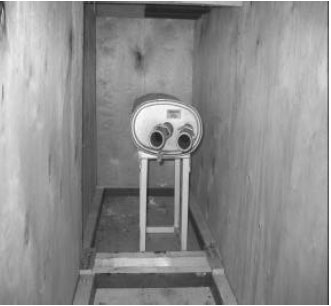 | |
| Fig. 2: | The posterior view of the box |
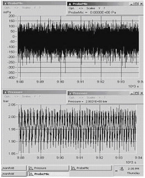 | |
| Fig. 3: | Sample plot by workstation at 4000 rpm |
The sensor is placed 15 cm from the muffler tip and also supported by a custom-made sensor support. The support is specially designed for both holding the sensor rigid against the exhaust gasses blowing through the tip and also protecting the sensors from high temperatures, as it is exposed to during high speed engine testing. The sound pressure level sensor tip is measured approximately 10 cm, cutting through the heat shields, taking the pressure of the exhaust sound at exactly 15 cm from the muffler tip. The sensor setup at the muffler tip is located inside the wooden box that acts as the sound dampening material and also separates the engine noise and the muffler noise. The sensor is then connected to the multi-channel system, which is then connected to the workstation using LAN port.
Heat shield is used at the exhaust manifold to protect the pressure sensor body and the cable connection from the high temperatures. The heat shield used is made of an aluminum plate measures approximately 15x15x1 cm and a hole is drilled at the center of the plate to make a passage for the sensor adapter. This setup has been tested for its durability and temperature handling and has been found to be adequate for temperature shielding for the sensor body. Thermocouple is inserted above the heat shield to take the manifold temperature and the coolant pipe (inlet and outlet) is connected to the sensor adapter to cool the sensor body. The coolant system is provided by the sensor supplier (Kistler) as part of the sensor setup and it is directly connected to the water sink. The sensor body temperature can be monitored by carefully monitoring the flow of the coolant (water) coming out from the sensor adapter. It is generally safe and accepted to take the safe working condition of the sensor as long as the water that comes out is still in the liquid phase.
Experimental procedures
| • | The sensors are linked to their respective ports in the IMC Multi-channel system. The multi-channel is then linked to the workstation via USB cable. |
| • | The IMC Device program is started and all the sensors are initialized and set up. |
| • | The sensor is set on their respective place (tailpipe and manifold), the distance between the sound pressure level and the tailpipe is measured and the sensor stand distance is adjusted to get 150mm distance between the sensor and the tip of the muffler tailpipe. The coolant (water) on the pressure sensor socket on the manifold is set to flow at average speed and the thermocouple is checked. The thermocouple must sit properly on the manifold pipe and there should be no leakage of coolant at the pressure sensor socket. |
| • | The engine is started and set to roam free on the idle speed. The graph of the parameters (temperatures, pressure and sound pressure level) is started to be plotted by the workstation. Figure 3 shows sample plots at 4000 rpm by the workstation. The engine is set free to roam until the parameters from the sensor are approximately constant. |
| • | The engine speed is varied and the readings are recorded. During high speed variations, the coolant coming out from the sensor socket is monitored. The coolant must not change form (liquid-vapor), once it changes form the engine must be switched off immediately or the pressure sensor will be burnt. |
RESULTS AND DISCUSSION
Figure 4 shows a steady increase pattern started from 1000 to 2000 rpm with the small increment in each step and from 2500 to 3000 rpm shows a linear pattern with the turning point near to the 3500 rpm which is a starting point for another steady increment but this time with steeper slope. These patterns can be explained by looking at the approach that the designer of the standard muffler took when designing the muffler. The main objective of the designer is to meet the requirement of the average usage of the design, which would be for the engine speed in between 2500 and 3500 rpm. The average rpm (converted speed of 70 to 100 km h-1 on the road) would create the best operating condition of this muffler design. It is understood that the design of the muffler must meet certain requirement set by the countries where the car are going to be marketed.
The result is relatively a very coarse approximation since the method of measuring the sound is not set according to any standard or guidelines but it is still useful in comparing the noise level as the data and the graph plotted show a relatively useful pattern.
 | |
| Fig. 4: | Variation of muffler noise with engine speed |
 | |
| Fig. 5: | Variation of manifold pressure with engine speed |
Figure 5 shows the variation of manifold pressure with engine speed. The change in the variants of the backpressure is closely related to the muffler design and the size of the muffler pipe. In addition, bends, flange and connectors in the muffler pipe also play an important role in adding to the restrictions in the flow of the gases.
At 3500 rpm, the pressure start to increase more drastically especially during very high speed section (4500-5500 rpm) and it is important to note that the turning point is the same for the sound pressure level graph (Fig. 4).
CONCLUSIONS
The parameters that govern the performance of the muffler are the muffler chamber design, restrictions of the flow of the exhaust gasses and the material of the muffler itself. The relationship between the noise and the backpressure is inversely proportional; lowering the noise level at the tip will result in high backpressure. However, this relationship is undesirable as we want to have a quiet muffler but with a small backpressure (ideal muffler). The design of the muffler chamber separation and arrangement is essential in determining the muffler characteristics. The average design will focus more on the average speed of the engine but that will sacrifice some characteristics of the ideal muffler. Thus the design of the muffler cannot satisfy the entire category (low to high speed) but it must be designed specifically for one use only, either for low, average or high speed. The general design proposal part is completed and it is hoped that the design can be turned into a real muffler that can be tested in the future. The experimental data show a general shape of an average design of the muffler which would be the most suitable for the test car model.