
Binghui Wu
Shanghai University of Electric Power, Shanghai, China
Jianjun Xi
Harbin institute of Technology, Harbin, Heilongjiang, China
Information Technology Journal
Year: 2014 | Volume: 13 | Issue: 15 | Page No.: 2437-2441


ABSTRACT
To ensure the safe and reliable operation of the space-arm when it working in the space, the space-arm should be locked reliably during launching. The optimal number and position of the locking spots should be determined when consider locking plan. The finite element analysis method was employed to accomplish modal analysis of space-arm under different constraints state. Modal analysis was employed in simplified model of the space-arm. The relative larger displacement of the part can be identified form mode shapes which can help to determine the key locking spots. Moreover, the auxiliary locking points will be selected according to the characteristics of the arm. Thus, all the locking spots of space-arm with a series of multi-joints were selected primary. Under such locking condition, the dynamic characteristics of the space-arm will be improved increasingly. Depending on the mass characteristics of the support mechanism, its model is simplified into springs and reasonable constraint equations were established to simulate their properties. This study provides an effective theoretical basis for dynamic design and optimization design of the space-arm and the lock-unlock mechanism.
PDF Abstract XML References Citation
Received: April 04, 2014;
Accepted: May 27, 2014;
Published: July 02, 2014
How to cite this article
Binghui Wu and Jianjun Xi, 2014. Research on Locking Position Determination of Space-arm Based on Modal Analysis. Information Technology Journal, 13: 2437-2441.
DOI: 10.3923/itj.2014.2437.2441
URL: https://scialert.net/abstract/?doi=itj.2014.2437.2441
DOI: 10.3923/itj.2014.2437.2441
URL: https://scialert.net/abstract/?doi=itj.2014.2437.2441
INTRODUCTION
With the rapid developing of space technology and robot technology, the space-arm has been widely used in aerospace and robotic domains, owning to its light mass, low energy consumption and strong adaptability. The space arm can replace the astronaut in repairing spacecraft under severe task environment. Without the application of butt joint device, the space arm can seize float-satellite and intercept space junk easily (Reif et al., 1999; Chen, 1991; Cassady et al., 2008). Space-arm is a series of multi-joint structure. Thus, it is a rigid-flexible mechanical system. Motor, speed reducer and a variety of sensitive sensors are assembled in the joints of space-arm. Then the mass is more concentrated.
The space-arm which is working in the weightless environment, is made by thin-walled components. In addition to withstand the manufacture, handling, transport, storage, testing and other environmental conditions on the ground, the space arm should bear the severe mechanical environment such as acoustic emission, vibration, shock and acceleration when launching (Das and Obal, 1998). To ensure the safety of the space-arm in the launch phase, it should be locked reliable (Deng et al., 2009).
The determination of number and position of the locking spot is a very important factor to ensure the safety under locking state. If the locking spot is too much, it will lead to increased mass and transmission cost greatly. More serious is that the excessive constraints will affect the performance of the space-arm. If the number of locking spot is not enough or the locking position is not appropriate, the space-arm will not be protected effectively (Liu et al., 2012). Therefore, the research on optimal locking spots’ number and appropriate location of space-arm has a very important significance.
Research on locking spots determination of space-arm is proposed in this study based on modal analysis theory.
MODAL ANALYSIS
Vibration environment of aerospace equipment is divided into low frequency vibration and high frequency vibration. Low frequency vibration is the main factor which causes the failure of spacecraft structure and medium-sized equipment. Therefore, the stiffness requirements are most important indicator for the structural design of space-borne device. Modal indicators can be used to evaluate the stiffness of structure (Herand et al., 2000; Sugiyama et al., 2006). Modal analysis of structure includes its natural frequency and corresponding modes. And the modal of the space-arm depends on the stiffness of structure, the mass distribution and the boundary conditions.
All structures have natural frequencies. When the excitation frequency is close to its natural frequency, the resonance of structure will occur. Differential equations of motion vibration system is shown in Eq. 1:
| (1) |
Where:
| M, C, K | = | Mass matrix, damping matrix and stiffness matrix |
| x, | = | Displacement vector, speed vector and acceleration vector of node |
| F(t) | = | Input force vector |
Let F(t) = 0, Eq. 1 becomes free vibration equation of the system. Because the damping has little effect on the system’s natural frequencies and mode shapes in engineering application, damping force can be ignored. Thus, undamped free vibration is shown in Eq. 2:
| (2) |
Free vibration of elastic objects can be decomposed into a series of simple harmonic. Solution vector of Eq. 2 can be assumed form of Eq. 3:
| (3) |
Where:
| ω | = | Natural frequency of the system |
| φ | = | Corresponding nth order vectors of natural frequency |
By submiting Eq. 3 into Eq. 2 as shown in Eq. 4:
| (4) |
Where:
| λ | = | Generalized eigenvalue and λ = ω2 |
Not all amplitude at each node is zero when free vibration. From Eq. 4, we obtain Eq. 5:
| (5) |
Solution (ω12, φ1), (ω22, φ2),… and (ω2n, φn), which present characteristics are obtained from Eq. 5, In which, ω1, ω2 ,… and ωn is a characteristic value of the equation. Natural frequency representative of the system is n. ω1 is called the fundamental frequency. φ1, φ2, … and φn are eigenvectors and they represent n order modes of the system (Qiu and Wang, 1994; Chijinatsu et al., 2002).
FINITE ELEMENT MODEL OF THE SPACE-ARM
The space-arm is stretched when it working in space, as shown in Fig. 1 (Jeong et al., 1999; Gibbs and Poirier, 1996; Asker, 1997). To save space, the space-arm must be folded to be locked when launching. Figure 2 shows the diagram of some space-arm when it folded.
Establish and simplified of physical model for the space-arm: There are two kinds of methods when establish the finite element model. They are CAD modeling and CAE modeling. The shape of space-arm is simple (Adams and Dutre, 2003; Mantyla, 1988). Thus, CAE modeling is employed here. Joints are connected by several flexible thin tubes in space-arm. Where the aspect ratio of the most arm tube is very small, it is not suitable for cell modeling. For this reason, solid modeling is conducted to build the model based on Boolean operations. Here, the small local structure is ignored and the structure is simplified. Utilize the surface to represent long thin tube and the torus to represent joints. The mass of joints are simulated by setting the material properties.
 | |
| Fig. 1: | Space arm on space station |
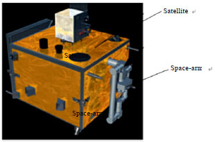 | |
| Fig. 2: | Space arm on satellite when lauching |
Cell division and connection: The space-arm is a rigid-flexible coupled system, so solid95 and shell93 are employed here to mesh joints and tubes, respectively. Each node in shell93 has six degrees of freedom which are UX, UY, UZ, ROTX, ROTY and ROTZ. And each node in solid95 has three degrees of freedom which are UX, UY and UZ. When using two different element types to mesh the arm, node displacement of adjacent element cannot be continuous. Solving this model cannot get correct results, because the force and torque are unable to achieve the correct transmission between two different elements. Therefore, we must establish a means to ensure proper connection between the different types of constraint equations.
To employ transition element method, a cross-interface between the joint and tube is generated. Shell element is introduced to generate transition element which can meet the requirement of restraint conditions. Therefore, the node freedom of adjacent elements is coupled. Space-arm is mounted on the satellite by a fixed end, Fig. 3 is the finite element model of the space-arm when the fixed end constrained.
DETERMINATION OF LOCKING POSITION FOR THE SPACE-ARM
Choice of locking positions on the space-arm: The space-arm is a semi-rigid body which is not strong. Support spot which has enough stiffness should be selected to withstand a certain pre-load. Thus, attachment between satellite and space-arm can be achieved effectively. When selecting the locking spot. The following questions are usually to be considered:
| • | Stiffness and strength of the structure at locking spot can withstand the preload when launching |
| • | Enough space is necessary to be provided for the connection between attachments at locking spot |
| • | The connection between the locking spot and the mounting spots should through the center of mass and inertia of the space-arm as possible |
| • | Pre-distortion and pre-stressing caused by preload at locking spot should be as small as possible |
 | |
| Fig. 3: | Finite element model of space-arm |
Determination of key locking spots for the space-arm: Modal solving was accomplished when the fixed end is restrained. To improve the solution speed, sub-block Lanczos method was employed. Figure 4 shows the mode of four stages.
As can be seen from Fig. 4, the vibration amplitude of joints which are far away from the fixed end is lager. Therefore, locking spots at these locations are very necessary. Locking positions are identified initially as shown in Fig. 5. It also can be seen from Fig. 4 that not every joints need to be locked.
Determination of the auxiliary locking spot for the space-arm: Although, most joints have been locking, it can be seen that there are significant displacement amplitude at the long-thin tube. For such series structure, the low rigidity region exist locally will affect the first-order natural frequency of the overall. Thus, it is necessary to add locking spots at the long-thin part.
From Eq. 2, it can be seen that natural frequencies and mode shapes of space-arm are determined by its stiffness matrix K and mass matrix M under locking condition. The mass of the locking mechanism is far less than that of the joints, so its quality may be negligible when further determination of the locking position. Mass-less spring element COMBIN14 is employed here to describe equivalent stiffness of the locking mechanism in three directions. At this time, the combination modeling with solid and element is proposed. The spring element acts on the corresponding node of each locking position. Figure 6 shows a schematic of connection between solid element and spring element.
The stiffness definition of three springs ab, cd and ce are along the launching directions X, Y and Z respectively. Node a and c are located at support spot on the arm. Fixed constraint is applied at node b, d and e. Relation of freedom degree at each node is achieved by the following coupled by Eq. 6-11:
| (6) |
| (7) |
| (8) |
| (9) |
 | |
| Fig. 4(a-d): | Modes shape of manipulator partially constrained (a) Ist order, (b) 2nd order, (c) 3rd order and (d) 4th order |
 | |
| Fig. 5: | Diagram of locking spots on space-arm |
| (10) |
| (11) |
Where:
| Rxi | = | Angle of rotation about the X axis of node i, i = a, b |
| Ryi | = | Angle of rotation about the Y axis of node i, i = c, d |
| Rzi | = | Angle of rotation about the Z axis of node, i = c, e |
| Uxi | = | Displacement along the X axis of node i, i = a, b |
| Uyi | = | Displacement along the Y axis of node i, i = c, d |
| Uzi | = | Displacement along the Z axis of node i, i = c, e |
| kx, ky, kz | = | Stiffness of lock mechanism in X, Y, Z-direction |
 | |
| Fig. 6: | Schematic of connection between different elements |
The relative position of two nodes on spring element can be guarantee by Eq. 6-8. Namely to ensure their connection is always parallel to the direction of corresponding emission. Equivalence relation of stiffness between locking mechanism and spring is guaranteed by Eq. 9-11. Correctness of the spring element definition is guaranteed by these constrained equations. Consequently, correctness of modal analysis of space-arm can also be ensured.
According to the above constraints, the constrained modal analysis of space-arm is achieved. Then the specific location of auxiliary locking spot can be found through the vibration modes according to specific lock mechanism.
CONCLUSION
This study builds a finite element model for space arm according to its locking condition in the procedure of launching. ANSYS is used to accomplish the model analysis of space-arm under the condition of locking to find the appropriate locking positions based on model theory. Through the model analysis of the space-arm, relation between arrangement of locking position and inherent frequency are revealed. This article provides a new method for determination chosen of lock position for space-arm and it also provides effective theory for the experimental model analysis of space arm.
ACKNOWLEDGMENT
This study was supported by the Heilongjiang Province Science and Technology Planning Project (No.W12A102).
REFERENCES
- Das, A. and M.W. Obal, 1998. Revolutionary satellite structural systems technology: A vision for the future. Proceedings of the IEEE Aerospace Applications Conference, Volume 2, March 21-28, 1998, Snowmass at Aspen, CO., USA., pp: 57-67.
CrossRef - Adams, B. and P. Dutre, 2003. Interactive boolean operations on surfel-bounded solids. ACM Trans. Graphics, 22: 651-656.
Direct Link - Jeong, J.W., S.H. Kim and Y.K. Kwak, 1999. Kinematics and workspace analysis of a parallel wire mechanism for measuring a robot pose. Mech. Mach. Theory, 34: 825-841.
CrossRefDirect Link - Reif, K., S. Gunther, E. Yaz and R. Unberhauen, 1999. Stochastic stability of the discrete-time extended kalman filter. IEEE Trans. Automatic Control, 44: 714-728.
Direct Link - Cassady, R.J., R.H. Frisbee, J.H. Gilland, M.G. Houts and M.R. LaPointe et al., 2008. Recent advances in nuclear powered electric propulsion for space exploration. Energy Convers. Manage., 49: 412-435.
CrossRefDirect Link - Sugiyama, H., J. Gerstmayr and A.A. Shabana, 2006. Deformation modes in the finite element absolute nodal coordinate formulation. J. Sound Vibrat., 298: 1129-1149.
CrossRefDirect Link - Chen, Z., 1991. Local observability and its application to multiple measurement estimation. IEEE Trans. Ind. Electron., 38: 491-496.
CrossRefDirect Link