
Wang Xu
Southwest Electronics and Telecommunication Technology Research Institute, University of Electronic Science and Technology of China, Chengdu, China
He Zi-Shu
Department of Electronic Engineering, University of Electronic Science and Technology of China, Chengdu, China
Information Technology Journal
Year: 2011 | Volume: 10 | Issue: 6 | Page No.: 1252-1257


ABSTRACT
The problem of TDMA (Time division multiple address) target tracking using the measurements of time of arrival (TOA) and direction of arrival (DOA) is addressed. According to the time synchronization property of TDMA system, the location model of quasi-periodic slot signal of TDMA target is established. The method of parametric Target Motion Analysis (TMA) is used in analyzing the observability condition of target position and deduces the theoretic analysis algorithm of location accuracy. The single-sensor location of TDMA target can be realized using measurements of more than two target positions without the linearization of nonlinear observation equation. The simulation results illustrate the validity of the proposed algorithms.
PDF Abstract XML References Citation
Received: February 17, 2011;
Accepted: March 05, 2011;
Published: May 13, 2011
How to cite this article
Wang Xu and He Zi-Shu, 2011. Single-Sensor Parametric Location Algorithm and Accuracy Analysis of TDMA Moving Target Based on TOA and DOA Measurements. Information Technology Journal, 10: 1252-1257.
DOI: 10.3923/itj.2011.1252.1257
URL: https://scialert.net/abstract/?doi=itj.2011.1252.1257
DOI: 10.3923/itj.2011.1252.1257
URL: https://scialert.net/abstract/?doi=itj.2011.1252.1257
INTRODUCTION
The bearing-only target motion analysis (TMA) is a classical single-sensor passive location algorithm (Nardone and Graham, 1997; Moon and Nordone, 2000) but its application is limited because the observer must do maneuver movement for moving emitter location (Jauffret et al., 2010; Hua et al., 2010).
Several researchers have investigated the methods of estimating the motion trajectory by using measurements of time of arrival (TOA) and direction of arrival (DOA) which is also a kind of TMA. The characteristics of the constant-speed motion and the periodicity of signal are commonly used in TMA. In literature of Yang and Zheng (1996), the nonlinear observation equation is linearized according to Taylor expansion method and Weighted Least Square (WLS) and Weighted Extended Kalman Filter (WEKF) are used in positioning the moving target without the sensor movement. Zhong-Kang et al. (2008) realized the target location by estimating the navigation angle, range and velocity. The observability condition of target position based on the measurements of TOA and DOA can be analyzed through the linearization technique of nonlinear observation equation (Li et al., 2004) and the observability analysis principle of nonlinear system (Xie et al., 2007).
The TDMA system is a kind of time synchronization one, that is to say, the time of TDMA terminal is synchronous with the system (Liu et al., 2007). The sending time difference between different slots of TDMA terminals is an integer multiple of the slot signal cycle. A TDMA target transmits slot signals with slot interval as a benchmark but whether it can transmit signals is restricted by the slot allocation rules (Lee and Chang, 2004; Qin et al., 2009). A target cannot transmit signals in each slot. So, the slot signal has quasi-periodic feature.
The closed-form TDMA target location algorithm with the variables of position coordinates, velocity and range is proposed based on the measurements of TOA and DOA in this study by parametric target motion analysis. The observability condition of target position is also analyzed according to the rank concept of matrix. The proposed algorithm simplifies the target localization process through the parametric target motion analysis.
SINGLE-SENSOR LOCATION MODEL OF TDMA TARGET
Quasi-periodic slot signal of TDMA system: Each terminal shares wireless channel with frame-slot mode in the TDMA system, as shown in Fig. 1.
The time interval of frame is the minimum distribution cycle (Tf) of TDMA system, suppose that Tf is a constant and the sending time of No. n frame is set to be tfu, there by:
| (1) |
 | |
| Fig. 1: | Frames and slots in TDMA system |
One frame is divided into Ns slots and the slot is the minimum allocation unit for every terminal. Each slot comprises synchronization header, data and protective time. Suppose that the slot duration is not changed.
s (n, m) is used for denoting the No. m slot within No. n frame, the sending time is ttnm, the slot duration time is Ts = Tf/Ns, there by:
| (2) |
It can be known from Eq. 1 and 2 that if the sending time of any one frame is known, the sending time of any slot in subsequent frame can be calculated.
Suppose that the sensor receives the signals of No. m slot in No. n frame, the relationship among the receiving time trnm, sending time ttnm and range r between sensor and TDMA terminal is as follows:
| (3) |
The sending time of any slot can be confirmed if the TDMA system synchronization time is known. For this synchronized TDMA system, the range r can be estimated according to the receiving time of slot signal. If the range r is known, the slot sending time can be confirmed through the slot receiving time, then the system synchronization time can be calculated through the Fig. 1 and 2, namely, the sending time of any slot can be determined.
Suppose the sensor receives two slot signals, their sending times, receiving times and ranges are, respectively represented as ![]() and
and ![]() ,
, ![]() and
and ![]() ,
, ![]() and
and ![]() . Before the synchronization relationship of the TDMA system is confirmed, n1, m1, n2 and m2 are unknown, the
. Before the synchronization relationship of the TDMA system is confirmed, n1, m1, n2 and m2 are unknown, the ![]() and
and ![]() and the difference between the two times can not be confirmed. Since the sending time difference of any two slots is the integer multiple (represented with Δm) of the slot period, there by:
and the difference between the two times can not be confirmed. Since the sending time difference of any two slots is the integer multiple (represented with Δm) of the slot period, there by:
| (4) |
The following relationship of receiving times can be obtained by Eq. 3:
| (5) |
The electromagnetic wave propagation time is taken into account during designing the TDMA system and protection time is preserved for each slot. In the above equation, ![]() represents the range difference of two slot signals to the sensor that is generally far smaller than the diffusion distance of the electromagnetic wave within the signal cycle Ts. If the following condition is met:
represents the range difference of two slot signals to the sensor that is generally far smaller than the diffusion distance of the electromagnetic wave within the signal cycle Ts. If the following condition is met:
| (6) |
Δm can be calculated by:
| (7) |
where, round () is a mathematic round function. From (5), the following is provided:
| (8) |
Therefore, the range difference between the different slots to sensor can be calculated according to the times of arrival (TOA) of slot signals.
Single-sensor location model: The two-dimensional target is taken as an example to illustrate the position principle. Assume that a TDMA target makes constant-speed movement in two-dimensional space with the velocity of (vx,vy) and the sensor is on coordinate origin as shown in Fig. 2. If the sensor receives N+1 signals provided with corresponding receiving time tr(k-i) and azimuth βk-i (i = 0, 1,..., N) which are, respectively sent by the moving target on the positions Tk, Tk-1, ... and Tk-N . The single-sensor location algorithm aims at realizing the estimation of two-dimensional coordinate (x, y) according to the receiving time tr(k-i) and azimuth βk-i (i = 0, 1,...,N) of the N+1 signals.
An actual target cannot make straight constant-speed movement always but its trajectory can be considered as a piecewise straight constant-speed movement one. For positioning a target of specific TDMA system, suppose that the cycle Ts of slot signal is known.
The target moving time between any two positions is the sending time difference of corresponding signals, namely:
| (9) |
According to Eq. 4,
| (10) |
Where:
| (11) |
According to Eq. 8, the range difference between the target positions at Tk-i and Tk-j to the sensor is:
| (12) |
Where the range equation is given by:
| (13) |
TARGET LOCATION ALGORITHM
As shown in Fig. 2, the following relationship exists for the target position Tk-i:
| (14) |
According to Eq. 12, use rk to express rk-i, then:
| (15) |
Equation 14 is deformed as:
| (16) |
In the same way, the following formula is derived for x-axis:
 | |
| Fig. 2: | Trajectory chart |
| (17) |
According to Eq. 16 and 17, 2 (N+1) equations can be established for N+1 positions. The matrix form of equations is:
| (18) |
where, Δt00 = 0, Δr00 = 0,
 |
The solvable necessary and sufficient condition of Eq. 18 is A to be a column full rank matrix, i.e.:
| (19) |
Suppose that Ai expresses the column vector of column i of matrix A. When the target makes the radial motion, the azimuth of target maintains invariable expressed as β0. According to Eq. 18, the following relationship exists:
| (20) |
Equation 20 explains that the 5th column vector is linearly correlation with the 1st and 2nd columns, i.e., Eq. 19 is untenable. So, Eq. 18 has no solution when the target makes the radial motion.
Equation 18 is get under the condition of straight constant-speed movement. If the target makes a circle movement, the range difference Δr0i along trajectory for any subscript i is equal to zero and the target position coordinates cannot be obtained because B in (18) is a zero-vector.
Above observability condition of target position is the same as literatures of Li et al. (2004) and Xie et al. (2007).
The position coordinates velocity components and range can be estimated simultaneously through Eq. 18.
THEORETIC ACCURACY ANALYSIS OF TARGET LOCATION
The differential of Eq. 16 is:
| (21) |
where, dy denotes the differential of variable y.
According to Eq. 10:
| (22) |
According to Eq. 12:
| (23) |
Eq. 21 can be expressed as:
| (24) |
In the same way, the differential of Eq. 17 is:
| (25) |
The 2 (N+1) equations can be established for N+1 positions. The matrix form of equations is:
| (26) |
Where:
 |
The solution of Eq. 26 is given by:
| (27) |
Where:
 |
Equation 27 illuminates that the target location estimation error is related with the measurement errors of location system, synchronization error of TDMA system and target states in two-dimensional space. The measurement errors of location system include ones of azimuth (dβ) and TOA measurements (dtr) of N+1 signals. The synchronization error of TDMA system is a jitter one of the slot signal period (dTs).
The target states related to location error include range, velocity, azimuth and navigation angle. Matrix C contains range rk-i and azimuth βk-i. Vector E contains velocity components vx and vy. The navigation angle θ of target movement is related to the components vx and vy which relation is as follows:
| (28) |
Suppose that the errors of azimuth, TOA and synchronization are mutually independent white noises with zero mean and respective variances of σβ2, σr2 and σs2. The covariance matrix of dX is:
| (29) |
Where:
 |
I (N+1) x(N+1) is a unit matrix.
The GDOP (Geometric Dilution of Precision) of location precision analysis is:
| (30) |
SIMULATION ANALYSIS OF TARGET LOCATION
In the simulation, the single-sensor location accuracy of TDMA target is analyzed along the target trajectory and with different amount of measurements.
Assume that a target makes constant-speed movement from left to right with the constant flight velocity of 200 m sec-1 and sends a signal every 5 sec. The trajectory is parallel to the X-axis in two-dimensional space.
Suppose that the RMS (Root Mean Square) error of range difference is 30 m which corresponds to the TOA measurement error, that of target system synchronization 1 microsecond and that of azimuth 0.5 degree.
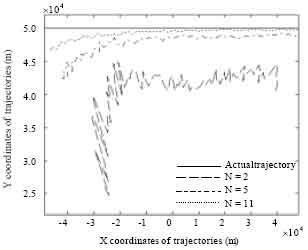 | |
| Fig. 3: | Relationship of actual and estimated trajectory |
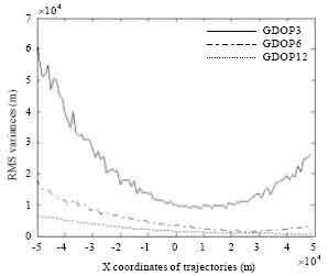 | |
| Fig. 4: | Location precision analysis of different amount of data |
The TOA and DOA measurements of 3 positions (N = 2), 6 positions (N = 5) and 12 positions (N = 11) are used in analyzing the location accuracy.
Figure 3 show the Actual and estimated trajectories. The more the amount of data is used, the closer the estimated trajectory approaches to the actual one.
Figure 4 show the simulation results of location accuracy. GDOPi is used in indicating the location accuracy using the measurements of i positions. According to Fig. 4, the following conclusions could be obtained:
| • | The more the amount of data is used, the better the location accuracy will be. The location accuracy using the measurements of 12 positions is obviously better than that of 6 and 3 positions |
| • | The closer the target approaches to sensor, the better the location accuracy will be |
| • | The positioning accuracy is asymmetric at the same distance on the left and right of sensor during the entire trajectory. This is because the current target position is estimated using previous measurements. The positioning accuracy on the right is better than that on the left at the same distance |
CONCLUSION
According to the quasi-periodic characteristic of slot signal of TDMA target, this paper makes the parametric target motion analysis to realize single-sensor target location based on the measurements of TOA and DOA. The main conclusions are as follows:
| • | The TDMA target can be positioned using the TOA and DOA measurements of more than two target positions. The more the amount of data is used, the better the location accuracy will be |
| • | The target location estimation error is related with the measurement errors of location system, synchronization error of TDMA system and target states in two-dimensional space |
REFERENCES
- Jauffret, C., D. Pillon and A.C. Pignol, 2010. Bearings-only maneuvering target motion analysis from a nonmaneuvering platform. IEEE Trans. Aerospace Electronic Syst., 46: 1934-1949.
CrossRef - Lee, K.D. and K.N. Chang, 2004. A real-time algorithm for timeslot assignment in multirate return channels of interactive satellite multimedia networks. IEEE J. Selected Areas Commun., 22: 518-528.
CrossRef - Nardone, S.C. and M.L. Graham, 1997. A closed-form solution to bearing-only target motion analysis. IEEE J. Oceanic Eng., 22: 168-178.
CrossRef - Qin, Y., J. Zhang and T. Zhang, 2009. Effect of TDMA timeslot assignment on traffic delay. Acta Electronica Sinica, 37: 2277-2283.
Direct Link - Hua, Y., W. Wen-Quan and L. Zhong, 2010. Observer trajectory optimization of maneuvering target for bearings-only tracking. Proceedings of International Conference of Information Science and Management Engineering (ISME), Aug. 7-8, Xi'an, pp: 207-211.
CrossRef