• [email protected]
  • +971 507 888 742
Submit Manuscript
SciAlert
  • Home
  • Journals
  • Information
    • For Authors
    • For Referees
    • For Librarian
    • For Societies
  • Contact
  1. Trends in Applied Sciences Research
  2. Vol 6 (9), 2011
  3. 992-1005
  • Online First
  • Current Issue
  • Previous Issues
  • More Information
    Aims and Scope Editorial Board Guide to Authors Article Processing Charges
    Submit a Manuscript

Trends in Applied Sciences Research

Year: 2011 | Volume: 6 | Issue: 9 | Page No.: 992-1005
crossmark

Facebook Twitter Digg Reddit Linkedin StumbleUpon E-mail
Research Article

Analysis of Steady State Stability of a Csi Fed Synchronous Motor Drive System with Damper Windings Included

A.B. Chattopadhyay, Sunil Thomas and Ruchira Chatterjee

ABSTRACT


Steady state stability criteria of A.C. drives play a dominant role for making the drive system practically successful. Generally such analysis is done using small perturbation model. But the complexity of the mathematical formulation depends on the nature of the drive system used. This study presents a detailed analysis of steady state stability criterion based on small perturbation model of a current source inverter fed synchronous motor drive system taking d-axis and q-axis damper winding into account using generalized theory of electrical machines. The modeling also clearly shows that even at no load the system satisfies steady state stability criterion. Routh-Herwitz criterion is used to finalize the result. The methodology of the proposed research work can be stated as follows: The synchronous motor has been treated as a five coil primitive machine model using the concept of generalized theory of electrical machines. Using the concept of Park’s transformation the armature current in d-q model has been represented by suitable equations as a function of armature current magnitude in phase model (IS) and the field angle (β). As the system under consideration is basically a current source inverter fed system, IS has been considered as a constant and as a consequence the field angle (β) finally appears as a control variable. Furthermore voltage balance equations of the five coils have been expressed in time domain and those equations has been transformed accordingly after applying Laplace transform technique and then small perturbation technique is applied on the transformed equations. Finally the transfer function Δβ (s)/ΔTL(s) have been formulated; where Δβ (s) and ΔTL (s) represent small change in transformed field angle and load torque, respectively. The analysis concludes that the absence of damper winding leads to instability of the machine system.
PDF Abstract XML References Citation
Received: February 28, 2011;   Accepted: April 14, 2011;   Published: May 30, 2011

How to cite this article

A.B. Chattopadhyay, Sunil Thomas and Ruchira Chatterjee, 2011. Analysis of Steady State Stability of a Csi Fed Synchronous Motor Drive System with Damper Windings Included. Trends in Applied Sciences Research, 6: 992-1005.

URL: https://scialert.net/abstract/?doi=tasr.2011.992.1005

Search


INTRODUCTION


For achieving flexibility in operation, the traditional method of feeding direct supply to the major components of an A.C. drive system i.e. synchronous machine or induction machine are avoided and the void is filled up by the use of power electronic converters. In this study, A.C. motor drives using inverter-fed synchronous machines are used in some specific application areas, certain features that make them preferable to induction motor drives (Marx et al., 2008). One of those specific examples is the accurate simultaneous speed control of a number of motors by using synchronous motors.

There are companion studies (Das and Chattopadhyay, 2004; Yan et al., 2008) in the direction of power electronic control of synchronous motor drive systems. Das and Chattopadhyay (2004) basically deals with the analysis of control mechanism of a synchronous motor drive system with the help of a cycloconvertor: direct torque control. Sayeef et al. (2008) explained the direct torque control of Permanent Magnet Synchronous Machine Motors (PMSM). Yan et al. (2008) discussed the direct torque control of PMSM taking the effect of saturation saliency into account.

Chan et al. (2008) introduced a flux-observer method to estimate the rotor speed of a PMSM. Fabijanski and Lagoda (2008) has been reported anthor study in 2008. This study deals in fuzzy logic control of inverter fed synchronous motor of inverter fed synchronous motor based on a simply mathematical model, algorithmic investigations of stability criteria.

Using fuzzy logic algorithm, similar work on PMSM (Uddin and Rahman, 2007) has been reported and the controller was found to robust for high-speed applications. Though most of the inverters used in A.C. drive are voltage source inverters, current source inverters are also being recognized due to simplicity, greater controllability and ease of protection. This study examines steady state stability aspects of a C.S.I. fed synchronous machine drive system considering the presence of damper winding on both direct and quadrature axis. There is a necessity of providing a damper winding in the q-axis to assure the steady-state stability at no-load. The present study also confirms the above said statement by presenting a rigorous analysis based on generalized theory of electrical machines by Adkins (1957). Furthermore, there exists an interesting research study (Al-Ohaly et al., 1997) in connection to the dynamics of a three phase synchronous motor being fed from a single phase supply, using state space model. Korshunov (2009) explained an interesting study in the area of stability analysis of a synchronous motor with permanent magnets by using small perturbation model. Even though the authors of the present study have used the axis model of synchronous motor for analysis of steady state stability, the reference (Korshunov, 2009) has drawn the attention because such work relates with the state variable model.

Chattopadhyay et al. (2011) does not involve synchronous motor as a topic of research but the main similarity lies in the fact that this study, also uses Laplace transforms as a tool for mathematical modeling using state variable approach applied to solar array power system. The study by Zayandehroodi et al. (2010) is basically a research work related to the fault location in a power system. This study uses neural network technique for the problem formulation but it can be linked up with the proposed research work involving synchronous motor in the sense that the same power system can consist of the synchronous motor drive system as a load. Ghorab et al. (2007) basically deals with the simulation of a power system consisting of a turbo generator using matlab. The points of similarity with the present study are:

• It is also a stability problem even though different technique like Lyaponov technique has been used
• Laplace transform has been used to carry out the block diagram approach
• Torque angle and power balance equations under dynamics have been used. It may be noted that the term torque angle (Ghorab et al., 2007) corresponds to the term field angle referred in the present study

Jazaeri et al. (2011) basically deals with the distance relay protection scheme implemented on a transmission line in presence of Unified Power Flow Controller (UPFC).The UPFC is a member of the FACTS family with attractive features. The present study involving synchronous motor drive system can be easily linked up with the findings of Jazaer et al. (2011). According to him synchronous motor can be included playing the role of the symbol of the motor shown in the Fig. 1 and 2. Babainejad and Keypour (2010) analysed the effect of electrical parameters of an Induction Generator on the transient voltage stability of a variable speed wind turbine system. The similarity of this study with the present study lies in the fact that the Induction generator also has been modeled in d-q frame through voltage balance and flux linkage equations. Furthermore this study uses the torque balance equations in the phase model which can be converted to d-q model using the well known torque balance equation i.e., Te = id Ψq.-Ψd iq.

There are many representative form of transfer function in association with the steady state stability analysis of a Current Source Inverter fed synchronous motor drive system. Taking the practical aspect into account, the present study targets to derive an expression in a suitable form for transfer function which is the ratio of the Laplace transfer of the small signal version of the change in angle (β) between the field (rotor) m.m.f. axis and armature (stator) m.m.f. axis to the Laplace transform of the small signal version of change in load torque (TL). The mathematical analysis in the said direction is presented in the subsequent section. The objective of the study is to diagnose the fact whether the synchronous motor with damper winding and fed through a current source inverter can sustain small perturbation in load torque or not. This analysis has been carried out from the view point of the concept of steady state stability criteria of an electrical drive system.

MATERIALS AND METHODS


The basic block diagram of the proposed scheme is shown in Fig. 1

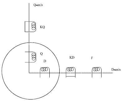
To have a better feeling of the method of analysis, the primitive machine model of the synchronous motor is drawn and it is shown in Fig. 2

In the following analysis, saturation is ignored but provision is made for inclusion of saliency and one number of damper winding on each axis. Following Park’s transform, a constant stator current of value is at a field angle ‘β’ can be represented by direct and quadrature axis currents as:

Image for - Analysis of Steady State Stability of a Csi Fed Synchronous Motor Drive System with Damper Windings Included
(1)

Image for - Analysis of Steady State Stability of a Csi Fed Synchronous Motor Drive System with Damper Windings Included
(2)

Designating steady state value by the subscript ‘0’ and small perturbation by Δ, the perturbation equations of the machines are:

Image for - Analysis of Steady State Stability of a Csi Fed Synchronous Motor Drive System with Damper Windings Included
(3)

Image for - Analysis of Steady State Stability of a Csi Fed Synchronous Motor Drive System with Damper Windings Included
(4)

Image for - Analysis of Steady State Stability of a Csi Fed Synchronous Motor Drive System with Damper Windings Included
Fig. 1: Drive configuration for open-loop current-fed synchronous motor control

Image for - Analysis of Steady State Stability of a Csi Fed Synchronous Motor Drive System with Damper Windings Included
Fig. 2: Primitive machine model of a synchronous motor

The transformed version of Eq. 3 and 4 are:

Image for - Analysis of Steady State Stability of a Csi Fed Synchronous Motor Drive System with Damper Windings Included
(5)

Image for - Analysis of Steady State Stability of a Csi Fed Synchronous Motor Drive System with Damper Windings Included
(6)

The generalized expression for electromagnetic torque of a primitive machine model is an established one and it is expressed as:

Image for - Analysis of Steady State Stability of a Csi Fed Synchronous Motor Drive System with Damper Windings Included
(7)

Small signal version of torque equation in time domain is expressed as:

Image for - Analysis of Steady State Stability of a Csi Fed Synchronous Motor Drive System with Damper Windings Included
(8)

Equation 8 after being transformed takes the shape as given by:

Image for - Analysis of Steady State Stability of a Csi Fed Synchronous Motor Drive System with Damper Windings Included
(9)

To tackle Eq. 9 in an easier form, it is expressed as:

Image for - Analysis of Steady State Stability of a Csi Fed Synchronous Motor Drive System with Damper Windings Included
(10)

where,

Image for - Analysis of Steady State Stability of a Csi Fed Synchronous Motor Drive System with Damper Windings Included
(11a)

Image for - Analysis of Steady State Stability of a Csi Fed Synchronous Motor Drive System with Damper Windings Included
(11b)

Image for - Analysis of Steady State Stability of a Csi Fed Synchronous Motor Drive System with Damper Windings Included
(11c)

Image for - Analysis of Steady State Stability of a Csi Fed Synchronous Motor Drive System with Damper Windings Included
(11d)

Image for - Analysis of Steady State Stability of a Csi Fed Synchronous Motor Drive System with Damper Windings Included
(11e)

The small perturbation model of the transformed voltage balance equations of F-coil, KD-coil and KQ are expressed as:

Image for - Analysis of Steady State Stability of a Csi Fed Synchronous Motor Drive System with Damper Windings Included
(12)

Image for - Analysis of Steady State Stability of a Csi Fed Synchronous Motor Drive System with Damper Windings Included
(13)

Image for - Analysis of Steady State Stability of a Csi Fed Synchronous Motor Drive System with Damper Windings Included
(14)

As the damper winding on d-axis and q-axis are short-circuited within themselves, ΔUkd=0 and Δukq = 0. So in transformed version Δukd(s) = 0 and Δukq(s) = 0 as shown in Eq. 13 and 14. Furthermore in general, the voltage fed to the field winding is fixed. That is why Δuf (s) = 0 as shown in Eq. 12.

From Eq. 12 and 13 it yields:

Image for - Analysis of Steady State Stability of a Csi Fed Synchronous Motor Drive System with Damper Windings Included
(15)

where,

Image for - Analysis of Steady State Stability of a Csi Fed Synchronous Motor Drive System with Damper Windings Included
(16a)

Image for - Analysis of Steady State Stability of a Csi Fed Synchronous Motor Drive System with Damper Windings Included
(16b)

Image for - Analysis of Steady State Stability of a Csi Fed Synchronous Motor Drive System with Damper Windings Included
(16c)

Image for - Analysis of Steady State Stability of a Csi Fed Synchronous Motor Drive System with Damper Windings Included
(16d)

Image for - Analysis of Steady State Stability of a Csi Fed Synchronous Motor Drive System with Damper Windings Included
(16e)

Image for - Analysis of Steady State Stability of a Csi Fed Synchronous Motor Drive System with Damper Windings Included
(16f)

Similarly Eq. 12 and 13 yields:

Image for - Analysis of Steady State Stability of a Csi Fed Synchronous Motor Drive System with Damper Windings Included
(17)

where,

Image for - Analysis of Steady State Stability of a Csi Fed Synchronous Motor Drive System with Damper Windings Included
(18a)

Image for - Analysis of Steady State Stability of a Csi Fed Synchronous Motor Drive System with Damper Windings Included
(18b)

From Eq. 14 it is obtained:

Image for - Analysis of Steady State Stability of a Csi Fed Synchronous Motor Drive System with Damper Windings Included
(19)

where,

Image for - Analysis of Steady State Stability of a Csi Fed Synchronous Motor Drive System with Damper Windings Included
(20a)

Image for - Analysis of Steady State Stability of a Csi Fed Synchronous Motor Drive System with Damper Windings Included
(20b)

Image for - Analysis of Steady State Stability of a Csi Fed Synchronous Motor Drive System with Damper Windings Included
(20c)

Image for - Analysis of Steady State Stability of a Csi Fed Synchronous Motor Drive System with Damper Windings Included
(20d)

Substituting Eq. 15, 17, 19 in Eq. 10, it yields:

Image for - Analysis of Steady State Stability of a Csi Fed Synchronous Motor Drive System with Damper Windings Included
(21)

Equation 21 can be re expressed as:

Image for - Analysis of Steady State Stability of a Csi Fed Synchronous Motor Drive System with Damper Windings Included
(22)

where,

Image for - Analysis of Steady State Stability of a Csi Fed Synchronous Motor Drive System with Damper Windings Included
(23a)

Image for - Analysis of Steady State Stability of a Csi Fed Synchronous Motor Drive System with Damper Windings Included
(23b)

Image for - Analysis of Steady State Stability of a Csi Fed Synchronous Motor Drive System with Damper Windings Included
(23c)

Image for - Analysis of Steady State Stability of a Csi Fed Synchronous Motor Drive System with Damper Windings Included
(23d)

Image for - Analysis of Steady State Stability of a Csi Fed Synchronous Motor Drive System with Damper Windings Included
(23e)

Image for - Analysis of Steady State Stability of a Csi Fed Synchronous Motor Drive System with Damper Windings Included
(23f)

Image for - Analysis of Steady State Stability of a Csi Fed Synchronous Motor Drive System with Damper Windings Included
(23g)

Image for - Analysis of Steady State Stability of a Csi Fed Synchronous Motor Drive System with Damper Windings Included
(23h)

Image for - Analysis of Steady State Stability of a Csi Fed Synchronous Motor Drive System with Damper Windings Included
(23i)

Image for - Analysis of Steady State Stability of a Csi Fed Synchronous Motor Drive System with Damper Windings Included
(23j)

Image for - Analysis of Steady State Stability of a Csi Fed Synchronous Motor Drive System with Damper Windings Included
(23k)

Image for - Analysis of Steady State Stability of a Csi Fed Synchronous Motor Drive System with Damper Windings Included
(23l)

Substituting the expressions for Δid (s) and Δiq (s) from Eq. 3 and 4 in Eq. 22 we have:

Image for - Analysis of Steady State Stability of a Csi Fed Synchronous Motor Drive System with Damper Windings Included
(24)

Equation 24 can be re-expressed as:

Image for - Analysis of Steady State Stability of a Csi Fed Synchronous Motor Drive System with Damper Windings Included
(25)

where,

Image for - Analysis of Steady State Stability of a Csi Fed Synchronous Motor Drive System with Damper Windings Included
(26a)

Image for - Analysis of Steady State Stability of a Csi Fed Synchronous Motor Drive System with Damper Windings Included
(26b)

Image for - Analysis of Steady State Stability of a Csi Fed Synchronous Motor Drive System with Damper Windings Included
(26c)

Image for - Analysis of Steady State Stability of a Csi Fed Synchronous Motor Drive System with Damper Windings Included
(26d)

The torque dynamic equation of a synchronous motor can be written as:

Image for - Analysis of Steady State Stability of a Csi Fed Synchronous Motor Drive System with Damper Windings Included
(27)

where, ω = motor speed in mechanical rad sec-1. J = polar moment of inertia of motor and load (combined). The small change in speed ‘ω’ equal to Δω can be related to small change in field angle, Δβ as given by:

Image for - Analysis of Steady State Stability of a Csi Fed Synchronous Motor Drive System with Damper Windings Included
(28)

The negative sign in equation physically indicates a drop in speed (ω) due to increase in field angle (β).

Based on Eq. 28, the following expression can be written:

Image for - Analysis of Steady State Stability of a Csi Fed Synchronous Motor Drive System with Damper Windings Included
(29)

The small-perturbation model of Eq. 27 can be written as:

Image for - Analysis of Steady State Stability of a Csi Fed Synchronous Motor Drive System with Damper Windings Included
(30)

Combining Eq. 29 and 30, it yields:

Image for - Analysis of Steady State Stability of a Csi Fed Synchronous Motor Drive System with Damper Windings Included
(31)

The transformed version of Eq. 31 with initial condition relaxed, comes out to be:

Image for - Analysis of Steady State Stability of a Csi Fed Synchronous Motor Drive System with Damper Windings Included
(32)

Substituting the expression for ΔTe (s) from Eq. 25 in Eq. 32 we have:

Image for - Analysis of Steady State Stability of a Csi Fed Synchronous Motor Drive System with Damper Windings Included
(33)

Equation 33 gives, after manipulation, a transfer function T (s) expressed as:

Image for - Analysis of Steady State Stability of a Csi Fed Synchronous Motor Drive System with Damper Windings Included
(34)

where,

Image for - Analysis of Steady State Stability of a Csi Fed Synchronous Motor Drive System with Damper Windings Included
(35a)

Image for - Analysis of Steady State Stability of a Csi Fed Synchronous Motor Drive System with Damper Windings Included
(35b)

Image for - Analysis of Steady State Stability of a Csi Fed Synchronous Motor Drive System with Damper Windings Included
(35c)

Image for - Analysis of Steady State Stability of a Csi Fed Synchronous Motor Drive System with Damper Windings Included
(35d)

Image for - Analysis of Steady State Stability of a Csi Fed Synchronous Motor Drive System with Damper Windings Included
(35e)

Image for - Analysis of Steady State Stability of a Csi Fed Synchronous Motor Drive System with Damper Windings Included
(35f)

The expression for:

Image for - Analysis of Steady State Stability of a Csi Fed Synchronous Motor Drive System with Damper Windings Included

in Eq. 34 gives a light in the direction of analysis of steady state stability criterion. In fact the denominator polynomial of right-hand side of Eq. 34, set to zero, becomes the characteristic equation. A Routh-Herwitz analysis of the characteristic equation will ultimately lead to the status of steady state stability. The detailed R-H analysis, considering a suitable example and the associated interpretation of the results are presented in the next section.

RESULTS


The denominator polynomial of the right hand side of Eq. 34 being set to zero, takes the form as given by:

Image for - Analysis of Steady State Stability of a Csi Fed Synchronous Motor Drive System with Damper Windings Included
(36)

The Routh-Herwitz table for Eq. 36 is developed taking suitable values of the polynomial co-efficient (K1 to K6). The machine data based on which the K1 to K6 are calculated are presented in Appendix. The calculated values of K1 to K6 are as follows:

K1 = 2.2871; K2 = 0.3585; K3 = 0.5577; K4 = 0.0776; K5 = 0.0023; K6 = 2.419'10-6

The coefficients of the first column of the R-H table do not show any change of sign. Therefore the steady state stability is assured.

Generally it is observed that at no-load, a synchronous motor without damper winding does not satisfy steady state stability criteria. At the no load condition with β0 = 0, the transfer function expressed in Eq. 34 for a C.S.I. fed synchronous motor with damper winding is modified for the motor without damper winding as given by the expression:

Image for - Analysis of Steady State Stability of a Csi Fed Synchronous Motor Drive System with Damper Windings Included
(37)

The denominator of the right hand side of the Eq. 37, being set to zero leads to a characteristic equation expressed as:

Image for - Analysis of Steady State Stability of a Csi Fed Synchronous Motor Drive System with Damper Windings Included
(38)

where,

Image for - Analysis of Steady State Stability of a Csi Fed Synchronous Motor Drive System with Damper Windings Included
(39)

Equation 39 clearly shows that the pair of roots of the characteristic equation are pure imaginary and complex conjugate. Such roots lead to a marginally stable or undamped system which does not clearly indicate the steady state stability criteria.

However, with damper winding considered and at no load (β0 = 0), the denominator polynomial of the right hand side of the Eq. 34 being set to zero is made subjected to R-H. analysis. With the R-H table formed the 1st column coefficient of that table do not show any change in sign. This assures that at no load also, the motor satisfies the steady state stability criterion. The values of the coefficient K1 to K6 for no load condition are calculated based on the machine data which are also present in the Appendix. The calculated values of K1 to K6 for no load condition are as follows:

K1 = 2.2871; K2 = 0.3585; K3 = 0.0421; K4 = 0.0045; K5 = 1.567'10-1; K6 = 1.7'10-7

DISCUSSION


From the study (Sergelen, 2007) we can observe that the study deals with the mathematical model of a synchronous motor energized through a power electronic converter and ultimately develops simulation results of time response of phase currents/phase voltages and motor speed. (This results are not in line with the results submitted in the present study because the objectives are different. However, a very good similarity is observed involving the fact that the study uses u-i relations and generalized torque equations in the primitive machine model and the same type of equations have also been used as a part of problem formulation in the present study.

Another comparison of the present study has been carried with Najafi and Kar (2007). In this study the main similarity lies in the method of modeling using voltage balance equations in the d-q model. As such there is no similarity in the results presented in the study, “Effect of Short-Circuit Voltage Profile on the Transient Performance of Saturated Permanent Magnet Synchronous Motors” and the present study. However, a minute observation on the literature on that study clearly indicates that the transient response on the performance figure takes torque angle, phase currents etc can lead to specific inference on stability criteria. Though the present study deals with the steady state stability analysis of a three phase synchronous motor the said similarity appears to be important as it falls in the broad category of stability studies on synchronous motors.

The results presented in the study, are similar as by the study of Kondo and Matsuoka (2007) uses block diagram approach for stability analysis of a permanent magnet Synchronous Motors for Railway Vehicle Traction in the Sudden Line Voltage Change and the formulation presented in the present study can easily lead to block diagram modeling in ‘S’ domain. Secondly both the studies are ultimately interested in the stability analysis but have some dissimilarity existing because the motor used in their work is permanent magnet synchronous motor and the study presented here uses synchronous motor consisting of physical field winding system. As a third aspect it is observed that, the study uses the concept of real part of the Eigen values to be negative for the assessment of the stability and the study presented here uses the same concept for stability assessment but in a slightly different form, that is on relative stability criteria based on Routh-Herwitz array.

The well known research study by Slemon et al. (1974) clearly indicates that the small perturbation model can be applied to a synchronous motor drive with current source inverter (the motor being without damper winding) for determination of steady state stability criteria. This particular study is in contrast of the proposed study because the authors of the present study have considered a synchronous motor with damper winding.

Jung et al. (2004) had drawn the attention to the authors of the present study. This study involves the stability improvement of a V/f controlled PWM inverter fed Induction motor using a dynamic current compensator. This particular study has been considered in contrast of the proposed study because induction motor can be treated as a singly excited magnetic field system where as synchronous motor considered by the authors of the present study can be treated as a multiple excited magnetic field system. Hence the opposition in the research philosophy is clearly observed.

The study of Tanneru et al. (2007) is related to induction motor as a component of the power system and transient modeling for such motor leading to the assessment of transient stability has been considered as the objective of the above study. This literature review is in contrast of the study carried by Tanneru et al. (2007) does not involve any analysis related to steady state stability criteria but it is clear that the model associated with the dynamics of Induction motor can be easily modified to be used in determination of the steady state stability criteria of the system.

CONCLUSIONS


This study highlights the following salient concluding points:

• The transfer function expressed in Eq. 34 has been developed in more general form such that the transfer function for no load condition can be derived from Eq. 34 directly just by substituting suitable marginal condition
• Statements similar to above are generally valid for the case of derivation of transfer function for a C.S.I. fed synchronous motor without damper winding

APPENDIX

List of symbols:

id = Current in the D coil in p.u.
iq = Current in the Q coil in p.u.
if = Current in the F coil in p.u.
ikd = Current in the d axis damper coil (KD) in p.u.
ikq = Current in the q axis damper coil (KQ) in p.u.
Ld = Self-inductance of D coil in p.u.
Lq = Self-inductance of Q coil in p.u.
Lmd = Mutual inductance along d axis in p.u.
Lmq = Mutual inductance along q axis in p.u.
Lff = Self-inductance of F (field) coil in p.u
Rf = Resistance of the F (field) coil in p.u.
Lkd = Self-inductance of the KD coil in p.u.
Rkd = Resistance of the KD coil in p.u
Lkq = Self-inductance of the KQ coil in p.u.
Rkq = Resistance of the KQ coil in p.u
β = Angle between the field (rotor) m.m.f. axis and armature (stator) m.m.f. axis

The machine data:

J = 8 p.u.
Ld = 1.17 p.u.
Lmd = 1.03 p.u.
Lq = 0.75 p.u.
Lmq = 0.61 p.u.
Lkkd = 1.122 p.u.
Lkkq = 0.725 p.u.
Lff = 1.297 p.u.
Rkd = 0.03 p.u.
Rkq = 0.039 p.u.
Rf = 0.0015 p.u.

When machine is at load:

is = 1 p.u.
if0 = 0.97 p.u.
ikd0 = 0 p.u.
ikq0 = 0 p.u.
β0 = 100

When machine is at no load:

is = 0.1 p.u.
if0 = 0.9 p.u.
ikd0 = 0 p.u.
ikq0 = 0 p.u.
β0 = 00

REFERENCES


  1. Das, S.P. and A.K. Chattopadhyay, 2004. Analysis, simulation and test results for a cycloconvertor-fed AC commutator-less motor drive with a modified machine model. IEEE Proc. Electr. Power Appl., 151: 622-627.
    CrossRefDirect Link

  2. Yan, Y., J.G. Zhu and Y.G. Guo, 2008. Initial rotor position estimation and sensorless direct torque control of surface-mounted permanent magnet synchronous motors considering saturation saliency. IET Electr. Power Appl., 2: 42-48.
    CrossRefDirect Link

  3. Sayeef, S., G. Foo and M.F. Rahman, 2008. Rotor position and speed estimation of a variable structure direct torque controlled IPM synchronous motor drive at very low speeds. Proceedings of the Australian Universities Power Engineering Conference, Dec. 14-17, Sydney, NSW, pp: 1-6.
    Direct Link

  4. Chan,T.F., W. Wang, P. Borsje, Y.K. Wong and S.L. Ho, 2008. Sensorless permanent-magnet synchronous motor drive using a reduced-order rotor flux observer. IET Electr. Power Appl., 2: 88-98.
    CrossRef

  5. Fabijanski, P. and R. Lagoda, 2008. A very simple fuzzy control system for inverter fed synhronous motor. Proceedings of the 13th Power Electronics Motion Control Conference, Sept. 1-3, Poznan, Poland, pp: 1040-1043.
    CrossRef

  6. Uddin, M.N. and M.A. Rahman, 2007. High-speed control of ipmsm drives using improved fuzzy logic algorithms. IEEE Trans. Ind. Electron., 54: 190-199.
    CrossRef

  7. Adkins, B., 1957. The Generalized Theory of Electrical Machines. 3rd Edn., John Wiley, New York.

  8. Al-Ohaly, A.A., R.M. Hamouda and M.A. Badr, 1997. Torsional oscillations associated with the starting of three phase synchronous motors from a single phase supply. IEEE Trans. Energy Convers., 12: 10-16.
    CrossRef

  9. Korshunov, A.I., 2009. Analysis of the static stability of a synchronous motor with permanent magnets by the classical method. Russ. Electr. Eng., 80: 81-85.
    CrossRef

  10. Sergelen, B., 2007. Mathematical model of salient pole synchronous motors supplied by a frequency converter. Proceedings of the International Forum on Strategic Technology, Oct. 3-6, Ulaanbaatar, pp: 390-390.
    CrossRef

  11. Najafi, S. and N.C. Kar, 2007. Effect of short-circuit voltage profile on the transient performance of saturated permanent magnet synchronous motors. Proceedings of the Power Engineering Society General Meeting, June 24-28, Tampa, FL, pp: 1-6.
    CrossRef

  12. Kondo, K. and K. Matsuoka, 2007. Stability analysis of permanent magnet synchronous motors for railway vehicle traction in a sudden line voltage change. Proceedings of the 27th Annual Conference of the Industrial Electronics Society, Nov. 29-Dec. 2, Denever, CO, pp: 1445-1450.
    CrossRef

  13. Marx, D., S. Pierfederici and B. Davat, 2008. Nonlinear control of an inverter motor drive system with input filter-large signal analysis of the DC-link voltage stability. Proceedings of the Power Electronics Specialists Conference, June 15-19, Rhodes, USA., pp: 498-498.
    CrossRef

  14. Ghorab, N., O. Ghorab and N.E. Debbache, 2007. Real time dynamic simulation of retrofitted turbogenerator in matlab/simulink environment. J. Applied Sci., 7: 3119-3122.
    CrossRefDirect Link

  15. Chattopadhyay, A.B., A. Choudhury and A. Nargund, 2011. State variable model of a solar power system. Trends Applied Sci. Res., 6: 563-579.
    CrossRefDirect Link

  16. Zayandehroodi, H., A. Mohamed, H. Shareef and M. Mohammadjafari, 2010. Automated fault location in a power system with distributed generations using radial basis function neural networks. J. Applied Sci., 10: 3032-3041.
    CrossRef

  17. Jazaeri, M., M. Gholamzadeh and M. Pazoki, 2011. Analysis of over/under-reaching of distance relay on transmission line in presence of UPFC. Trends Applied Sci. Res., 6: 580-594.
    CrossRefDirect Link

  18. Babainejad, S. and R. Keypour, 2010. Analysis of transient voltage stability of a variable speed wind turbine with doubly fed induction generator affected by different electrical parameters of induction generator. Trends Applied Sci. Res., 5: 267-278.
    CrossRef

  19. Tanneru, S., J. Mitra, Y.J. Patil and S.J. Ranade, 2007. Effect of large induction motors on the transient stability of power systems. Proceedings of the 39th North American Power Symposium, Sept. 30-Oct. 2, Las Cruces, NM, pp: 223-228.
    CrossRef

  20. Slemon, G.R., S.B. Dewan and J.W.A. Wilson, 1974. Synchronous motor drive with current-source inverter. IEEE Trans. Ind. Appl., 10: 412-416.
    CrossRef

  21. Jung, J.H., G.Y. Jeong and B.H. Kwon, 2004. Stability improvement of V/f-controlled induction motor drive systems by a dynamic current compensator. IEEE Trans. Ind. Electron., 51: 930-933.
    CrossRef

Search


Related Articles

Real Time Dynamic Simulation of Retrofitted Turbogenerator in Matlab/Simulink Environment
Automated Fault Location in a Power System with Distributed Generations using Radial basis Function Neural Networks
Analysis of Transient Voltage Stability of a Variable Speed Wind Turbine with Doubly Fed Induction Generator Affected by Different Electrical Parameters of Induction Generator
State Variable Model of a Solar Power System
Analysis of Over/Under-reaching of Distance Relay on Transmission Line in Presence of UPFC

Leave a Comment


Your email address will not be published. Required fields are marked *

Useful Links

  • Journals
  • For Authors
  • For Referees
  • For Librarian
  • For Socities

Contact Us

Office Number 1128,
Tamani Arts Building,
Business Bay,
Deira, Dubai, UAE

Phone: +971 507 888 742
Email: [email protected]

About Science Alert

Science Alert is a technology platform and service provider for scholarly publishers, helping them to publish and distribute their content online. We provide a range of services, including hosting, design, and digital marketing, as well as analytics and other tools to help publishers understand their audience and optimize their content. Science Alert works with a wide variety of publishers, including academic societies, universities, and commercial publishers.

Follow Us
© Copyright Science Alert. All Rights Reserved