
A. V. Adedayo
Department of Materials Science and Engineering, Obafemi Awolowo University, Ile-Ife, Nigeria
Asian Journal of Materials Science
Year: 2012 | Volume: 4 | Issue: 1 | Page No.: 1-12


ABSTRACT
Semi Solid Metallurgy is a near-net-shape manufacturing process that has been identified to possess numerous process advantages. While SSM is already a viable manufacturing method, it is still under intensive development and critical breakthroughs are still much expected. Merton C. Flemings, the founder of semi solid metallurgy identified the path forward to achieving the much expected breakthroughs. The identified some key research directions include: the formulation of better understanding of the mechanism whereby desired microstructure for SSM forms. Development and full application of mathematical models as related to SSM is also seen to be very vital. In this present study, theoretical expositions are made on mechanism of evolution of desired microstructure in SSM. The influence of temperature, intermetallics and furnace design during thixocasting on the SSM structure is also mathematically elucidated.
PDF Abstract XML References Citation
Received: October 31, 2011;
Accepted: February 11, 2012;
Published: February 29, 2012
How to cite this article
A. V. Adedayo, 2012. Factors Influencing Semi-Solid Microstructure. Asian Journal of Materials Science, 4: 1-12.
DOI: 10.3923/ajmskr.2012.1.12
URL: https://scialert.net/abstract/?doi=ajmskr.2012.1.12
DOI: 10.3923/ajmskr.2012.1.12
URL: https://scialert.net/abstract/?doi=ajmskr.2012.1.12
INTRODUCTION
Semi Solid Metallurgy (SSM) is a very trendy near-net-shape manufacturing process. It is of growing industrial significance and the high level of excitement and optimism that pervades the subject is reflected by the large number of publications, the series of conferences and workshops held on the subject.
Whatever, the route employed for SSM, several advantages of the process are clear (Flemings, 2000; Adedayo, 2011a, b). SSM employs reduced temperature when compared to the casting of superheated melts. The generally accepted advantages of hardware performance and energy economy, achieved due to reduced operating temperatures are universally positive for all alloys (Czerwinski, 2008) and includes the following: lower energy consumption, no handling of liquid metal, longer die life, better yield from the raw material due to lower oxidation and evaporation, and fewer other losses related to melt overheating.
Although, SSM is already a viable manufacturing method, it is still under intensive development and critical breakthroughs are still much expected (Czerwinski, 2008). The production of SSM feedstock is of considerable interest and current research effort is concentrated on production of feedstock alloys where the primary phase in the microstructure consists of globularized particles (Reisi and Niroumand, 2008; Paes et al., 2006; Margarido and Robert, 2003). In general, microstructure affects materials properties (Araoyinbo et al., 2010; Omotoso and Ogunsile, 2010; Abdi et al., 2009; Omotosho et al., 2012; Abdullah et al., 2009).
Aside from the major efforts that will certainly take place in overall process development (Flemings, 2000), the Toyota Emeritus Professor of Materials Science and Engineering at Masachuesset Institute of Technology (MIT) identifies some key research directions as the path forward for SSM. Foremost of the key research directions is formulation of better understanding of the mechanism where by the desired SSM microstructure is formed. Also, the development and full application of mathematical models relevant to SSM would be a very vital tool in this quest. Recently, many publications have established the potentials of mathematical models to describe the hydrodynamic characteristics of two phase systems (Kwaire et al., 2010; Abdul-Bari and Yunus, 2009).
In this present study, theoretical expositions are made on some important features of evolution of required microstructure of the SSM component. The understanding of the theories of evolution of required microstructure is vital and useful for SSM process designs and other engineering applications. This will also provide insight on fundamentals for achieving the much expected critical breakthroughs in SSM.
METHODS FOR PRODUCING GLOBULAR CRYSTALS
Under conventional solidification conditions, dendritic microstrutres result (Browne et al., 2003). This process is well discussed in literatures (Kurz and Fisher, 1998; Rajput, 2006). The process of producing globular crystals in metallic alloys which is suitable for SSM was commonly believed to rely upon the fragmentation of the secondary dendrite arms during solidification (Browne et al., 2003; Doherty et al., 1984). A number of technologies have been developed over the last three decades, mainly in a laboratory environment, to take advantage of the unique behavior of semi-solid slurries to produce globular crystals. All the technologies can be divided into two fundamentally different basic routes: thixo-processing and rheo-processing. There are also hybrids that combine features of both routes.
The thixo-route involves two stages: first, billet preparation and, second, billet re-heating and isothermal holding within the mushy zone of the alloy. The crystals which form in the process of conventional solidification of a metal have structures which are dendritic, lamellar or fibrous, needle type (acicular) or globular, depending on the rate of cooling and the type and amount of admixtures or impurities (intermetallics) in the melt (Rajput, 2006). Perfect crystals of proper external shape can be obtained only if crystallization develops under condition when the degree of super cooling is very slight and the metal has a very high purity (Rajput, 2006). In great majority of cases, branched or tree-like crystals are obtained which are called dendrites. Figure 1 shows steps in the formation of a dendritic crystal.
A crystal nucleus forms as shown in (a) and then proceeds to send out shoots or axis of solidification as shown in Fig. 1b-d forming the skeleton of a crystal. Atoms then attach themselves to the axes of the growing crystal from the melt in progressive layers (layers 1, 2, 3, 4 and 5 as shown in Fig. 1e), finally filling up these axes, and thus forming a completed solid crystal.
However, during billet re-heating thixo-processing of the metallic alloy there is partial melting of the structures in the alloy. These may be any of the various compounds found in the alloy. Constituents with low melting points melt into liquid. Also, as the temperature rises, there is break-up of the primary and secondary axis into smaller unit and random re-orientation of the break-up network. Due to high diffusion rates in the mushy zone, atoms of the melted constituents diffuse from the liquid phase and joined up with the existing solid crystals. This phenomenon leads to evolution of new structure which is globular. This process is shown in Fig. 2.
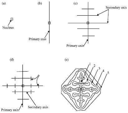 | |
| Fig. 1: | Formation of dendritic crystals (Rajput, 2006) |
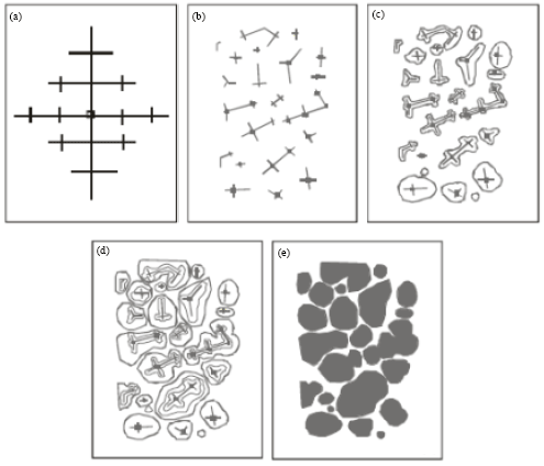 | |
| Fig. 2: | Development of globular structure (a) Dendritic structure formed during solidification in a casting (b) Breakdown of dendritic network to form new nuclei during semi solid isothermal heating, (c), (d) and (e) The process of emergence of globular structure (Adedayo, 2011a) |
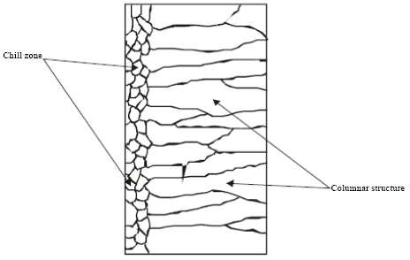 | |
| Fig. 3: | Sketch of chill zone and columnar structure in conventional casting |
TEMPERATURE AND GLOBULAR MORPHOLOGY
In conventional castings, the material in the interior of the ingot cools more slowly and solidification takes place at a higher temperature. Usually, some of the grains near the surface simply grow inwards as heat flows outwards. The resulting structure is columnar (illustrated in Fig. 3). The columnar grains are not randomly oriented but rather have their directions of most rapid growth normal to the mould walls, which is the direction of heat withdrawal. In general, crystals grow in certain directions depending on some factors such as direction of heat flow and presence of impurities.
The direction of heat flow is a function of the temperature field. In mathematical physics, the temperature field is the totality of temperature values at a given point in time for all points of the space considered in which heat transfer process takes place. During solidification, the temperature at various points change with time and heat propagates from places at a higher temperature to places at lower temperature. It follows that during solidification, there is variation of temperature both in space and time.
INFLUENCE OF FURNACE DESIGN ON SEMI SOLID MICROSTRUCTURE
Heat flow patterns in furnaces have been studied using Finite Element (FE) analysis by Oluwole et al. (2009). This study revealed that the design of a furnace has effects on the heat flow characteristics of the furnace. The long term stability of the furnace was also found to be dependent on the design. The thermal stability of the furnace determines the temperature profile within the furnace per time. Consider Fig. 4 and 5, these show that the furnace design has significant effects on the temperature gradients in the furnace.
For alloy materials, when the grain boundary grooving occurs such that the boundary intersects the liquid-solid interface, the curvature in the neighborhood of the groove is determined by the requirement that (Fleming, 1974):
| (1) |
where, T* is the liquid-solid interface temperature, G is the thermal gradient and ΔX is the distance back from the isotherm at Tm, the equilibrium melting point of the alloy material (the liquidus temperature).
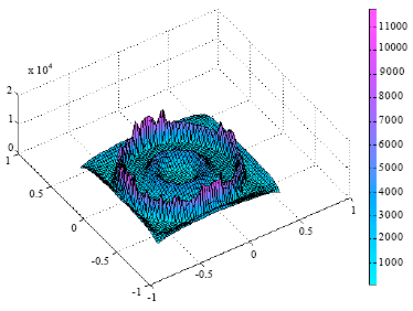 | |
| Fig. 4: | A 3-D presentation of a salt bath furnace showing temperature gradients during heat transfer in the furnace (A high temperature gradient was observed in the air gap insulation) (Oluwole et al., 2009) |
 | |
| Fig. 5: | A 3-D salt bath furnace without air-gap spacing insulation within refractory lining showing temperature gradients during heat transfer in the furnace (A high temperature gradient was observed concentrated in the glass wool fibre segment) (Oluwole et al., 2009) |
But also:
| (2) |
| (3) |
where, ΔGL and ΔGs are the changes in free energies of liquid and solid, respectively. Vs is the volume of the solid, λ is the surface curvature in the groove neighborhood, Tr is the decrease in equilibrium melting point, σ is the surface energy of the interface. Assuming that ó is isotropic and does not change as surface area changes, at equilibrium (Fleming, 1974):
| (4) |
It follows that:
| (5) |
| (6) |
| (7) |
| (8) |
| (9) |
| (10) |
But:
| (11) |
| (12) |
| (13) |
But the curvature λ at a point is described as the limit (provided it exists) of the average curvature λav (Fig. 6) of an arc as the terminal point of the arc tends to its initial point (Bermant and Aramanovich, 1989). For arc M0 M1, as the terminal point of the arc M1 tends to its initial point M0:
| (14) |
where, φ is the angle of contingence of the arc (in radians).
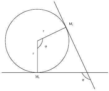 | |
| Fig. 6: | Geometric description of relationship between r, φ and curvature (λ) |
So:
| (15) |
Thus:
| (16) |
Therefore:
| (17) |
Then:
| (18) |
The thermal gradient G is dependent on the stability of the furnace (Oluwole et al., 2009). If the temperature field of the system is transient i.e.:
| (19) |
where, x, y, z are point coordinates, t is time. The thermal gradient G will be dependent on time and the value of r will vary with time. Transient temperature fields are experienced during heating and cooling of a system.
During isothermal heating, the temperature field is steady i.e.:
| (20) |
Temperature gradient G will be essentially constant and independent of time. This gives an essentially constant value for r. This results in a spheroidal morphology. This shows that the ability of the heat treatment furnace to maintain an efficient steady-state will affect the morphology of the evolving crystal. Also, value of G (whether G<0 or G>0) will affect the concavity or convexity of the resulting microstructure.
INTERMETALLICS AND GLOBULAR MORPHOLOGY
The relationship between curvature λ and surface energy σ of the interface can be expressed by Eq. 12, as:
| (12) |
However, for a multi-component surface, the resultant surface energy will depend on crystallographic orientation and the surface energies of the constituent components. The resultant surface energy may be evaluated using Cassie equation (Adedayo et al., 2010; Adedayo, 2010):
| (21) |
i.e.:
| (22) |
where, Cosθ is proportional to the resultant surface energy, fi is the fraction of component i and θi is the contact angle of component i. Therefore:
| (23) |
Therefore:
| (24) |
This shows the dependence of r and hence λ on:
| (25) |
FORMULATION FOR PREDICTING COMPOSITION OF A GLOBULE
SSM is feasible only with alloys because there exists a MUSHY zone in their phase diagram. Generally, alloys are systems containing two or more different elements. In the slurry zone the constituents of alloys may react to form intermetallics and eutectics. Actually, the reacting species in the alloys are in a balance with the products of reaction because a sort of equilibra is established within the system. Also, in the mushy (slurry) zone, there is a balance between the solid and the liquid phases of the alloy present. This leads to solute redistribution between the solid and the liquid and thus varied compositions of the solid and the liquid. At temperature T, a general material balance (conserving solute atoms) is written:
| (26) |
where, fs and fL are weight fractions of solid and liquid, respectively. Cs and CL are the solid compositions, respectively. C0 is the initial composition of the alloy. At temperature T, solid of composition Cs is freezing from liquid of composition CL. A quantitative expression is easily obtained by equating the solute rejected when a small amount of solid forms with the resulting solute increase in the liquid. This balance is:
| (27) |
If:
| (28) |
where, k is defined as the partition ratio then:
| (29) |
| (30) |
Therefore:
| (31) |
Substituting the equilibrium partition ratio and integrating from Cs = kC0 at fs = 0, the composition of the globule at the liquid-solid interface Cs as a function of fraction of solid is given as:
| (32) |
| (33) |
| (34) |
Integrating from 0 to fs and from kC0 to Cs:
| (35) |
Substituting 0 and fs for values of fs and kC0 and Cs for values of Cs:
| (36) |
| (37) |
| (38) |
Therefore:
| (39) |
Or in terms of liquid composition and fraction liquid:
| (40) |
TEMPERATURE AND GLOBULE FRACTION
In metal alloys and other alloys where the liquid-solid interface is close to equilibrium, liquid composition within any given interdendritic space is almost uniform and close to the liquidus line of the phase diagram. This assumes a constant liquidus slope ML (Fig. 7):
where, T is the temperature of the volume element, Tm is the melting point of the pure solvent metal. Thus:
| (41) |
But:
CL = C0fLk-1 |
Where:
| (42) |
Therefore:
| (43) |
| (44) |
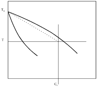 | |
| Fig. 7: | Model of the liquid-solid region |
Taking logarithm of both sides:
| (45) |
| (46) |
| (47) |
Globule fraction (solid fraction) is given as:
| (48) |
| (49) |
| (50) |
| (51) |
The formulation for predicting fraction of a globule is given as:
fs = 1-(ML(T-Tm)/C0)(1/(k-1)) |
CONCLUSION
The theoretical exposition made in this study revealed that globular microstructure evolves as a result of breakdown of dendritic structure during thixocasting of the conventionally cast materials. The role played by furnace design, intermetallics and temperature on the evolution of globular morphology has also been elucidated. Also, formulations for predicting composition of a globule have been provided.
REFERENCES
- Abdi, S., Y. Ouroua and O. Menchi, 2009. Development and characterisation of metal matrix composite steel/Cu-Zn. Asian J. Mater. Sci., 1: 1-7.
CrossRefDirect Link - Abdul-Bari, H.A. and R.B.M. Yunus, 2009. Drag reduction improvement in two phase flow system using traces of SLES surfactant. Asian J. Ind. Eng., 1: 1-11.
CrossRefDirect Link - Abdullah, H., R. Silvia and J. Syarif, 2009. Study of structure, surface morphology and optical property on ZnO: Al thin films as anti-reflecting coating. Asian J. Applied Sci., 2: 191-196.
CrossRefDirect Link - Adedayo, A.V., 2011. Development processes of globular microstructure. J. Miner. Mater. Charact. Eng., 10: 651-659.
Direct Link - Adedayo, A.V., O.A. Oyetoyan, S.A. Ibitoye and A.A. Adeleke, 2010. Effects of iron fillings and snail shell on the properties of green moulding sand. South Pacific J. Natur. Sci. Eng., 28: 58-62.
Direct Link - Araoyinbo, A.O., M.N.A. Fauzi, S. Sreekantan and A. Aziz, 2010. A novel process to produce nano porous aluminum oxide using alkaline sodium phosphate electrolyte. Asian J. Mater. Sci., 2: 63-68.
CrossRefDirect Link - Browne, D.J., M.J. Hussy, A.J. Carr and D. Brabazon, 2003. Direct thermal method: New process for development of globular alloy microstructure. Int. J. Cast Metals Res., 16: 418-426.
Direct Link - Flemings, M.C., 2000. Semi solid forming: the process and the path forward. Metall. Sci. Technol., 18: 3-4.
Direct Link - Oluwole, O.O., P.O. Atanda and B.I. Imasogie, 2009. Finite element modeling of heat transfer in salt bath furnaces. J. Miner. Mater. Charact. Eng., 8: 229-236.
Direct Link - Omotosho, O.A., O.O. Ajayi, O. Fayomi and V.O. Ifepe, 2012. Evaluating the deterioration behaviour of mild steel in 2 M sulphuric acid in the presence of Butyrospermum parkii. Asian J. Applied Sci., 5: 74-84.
CrossRefDirect Link - Paes, M., E.G. Santos and E.J. Zoqui, 2006. Obtention rheocast structure for Al-4.5wt% Cu alloy: Comparison ultra-refining and electromagnetic stirring. J. Achievements Mater. Manuf. Eng., 9: 21-27.
Direct Link