
Seyed Mehdi Abedi
Islamic Azad University, Sari Branch, Sari, Iran
Hani Vahedi
Islamic Azad University, Sari Branch, Sari, Iran
Trends in Applied Sciences Research
Year: 2013 | Volume: 8 | Issue: 1 | Page No.: 46-54


ABSTRACT
Shunt Active Power Filter (APF) is one of the most important equipment in power systems which is employed to remove the current harmonics and compensate reactive power. Hysteresis Current Control (HCC) is the simplest and fastest modulation technique. The main issue in implementing the Fixed Band Hysteresis Current Control (FBHCC) in APFs is its variable switching frequency results in increasing the switching losses and acoustic noise as well as injecting vast range of high frequency harmonics into the system current waveform. To avoid this situation, Adaptive HCC (AHCC) methods with the variable hysteresis bands have been recommended in literature. The AHCC can fix the switching frequency and remedy the mentioned problems significantly. In this study a simpler equation has been proposed to calculate the value of adaptive hysteresis bandwidth instantaneously. The proposed method reduces the size of calculation in controller which makes it response faster while shows the proper results in harmonics elimination and decreasing switching losses. The simulations have been done to validate the efficiency of this method by Matlab/Simulink.
PDF Abstract XML References Citation
Received: January 08, 2013;
Accepted: March 30, 2013;
Published: June 15, 2013
How to cite this article
Seyed Mehdi Abedi and Hani Vahedi, 2013. Simplified Calculation of Adaptive Hysteresis Current Control To Be Used In Active Power Filter. Trends in Applied Sciences Research, 8: 46-54.
URL: https://scialert.net/abstract/?doi=tasr.2013.46.54
URL: https://scialert.net/abstract/?doi=tasr.2013.46.54
INTRODUCTION
Voltage and current harmonics are matter of concern in most research on power networks. One of the equipment which is used to remove such harmonics is active power filters (APF) that are employed by many researchers and industries to suppress the current harmonics generated by nonlinear loads which has been shown in Fig. 1 (Singh et al., 2004, 2005; Emadi et al., 2005). An APF includes an inverter to produce the reference current. At first, the reference current is calculated based on system current harmonics. Instantaneous reactive power theory is reported in the literature (Akagi et al., 1984) and employed in this study to extract the system current and calculation of reference current. Afterwards, the switching methods such as PWM, HCC and etc., are used to generate and inject the calculated reference current.
The HCC technique is the easiest and cheapest PWM method to implement and control APF with some charactristics like high accuracy, good dynamic performance and stability (Kazmierkowski et al., 2002). On the other hand, the main weakness of conventional fixed-band hysteresis technique (FBHCC) is its variable switching frequency that causes acoustic noise and difficulty in the designing of input filters (Bina and Pashajavid, 2009). AHCC method was first introduced by Bose (1990). Using this method, the hysteresis bandwidth will be calculated instantaneously and adaptively related to the system parameters.
 | |
| Fig. 1: | Power system diagram with APF |
The various bandwidth leads to smoother switching speed which fixes the switching frequency in this method (Bose, 1990). Other improvements on HCC are reported in literature (Vahedi and Sheikholeslami, 2010a, b, 2012).
In next section the instantaneous power theory is described which is used to extract the harmonics components of the system current. Later the FBHCC and AHCC have been demonstrated. Afterwards, the proposed method in reducing the size of calculation of adaptive band has been described. Finally, some simulations have been done with Matlab/Simulink and the results have been discussed. By comparing the results of simulations, the advantages of proposed calculation have been proved.
Instantaneous power theory: To compensate the current harmonics of a nonlinear load in power systems, the source current should be extracted which is the sum of main sinusoidal component and harmonic components. The harmonic content of source current will be used to calculate the reference current. The derived reference current should be modulated to generate the associated pulses that order the inverter switches to inject the appropriate current into the system which can compensate the load harmonics.
Instantaneous reactive power theory (p-q theory) presented by Akagi et al. (1984) is one of the popular and attractive reference current extraction method which is simple in implementation. The p-q theory could be briefly reviewed as follow (Akagi et al., 1984).
Assume a three-phase load with the instantaneous voltages as v(t) = [va(t) vb(t) vc(t)]t and the instantaneous currents as il(t) = [ila(t) ilb(t) ilc(t)]t (Fig. 1). Using (1), v(t) and il(t) can be converted to o-α-β coordination where C is the matrix (2):
| (1) |
 | (2) |
Assume that there is no zero sequence current (il0(t)). Thus, the instantaneous active (p(t)) and reactive (q(t)) powers are as the following:
| (3) |
p(t) and q(t) can be decomposed to the average parts (![]() (t),
(t), ![]() (t)) and the oscillating parts (
(t)) and the oscillating parts (![]() (t),
(t), ![]() (t)). It is notable that
(t)). It is notable that ![]() (t) is produced by the fundamental harmonic of the positive sequence component of the load current. Therefore, in order to compensate the harmonics and the instantaneous reactive power, compensation reference currents can be extracted as follow:
(t) is produced by the fundamental harmonic of the positive sequence component of the load current. Therefore, in order to compensate the harmonics and the instantaneous reactive power, compensation reference currents can be extracted as follow:
| (4) |
| (5) |
Hysteresis current control: Hysteresis current control is one of PWM methods used for generating pulses to order the power switches of inverter. Among the various current control techniques, HCC is widely used due to the fast response, simple implementation, negligible tracking error, inherent robustness to load parameters variations and proper stability. As it is mentioned in the research, HCC has high accuracy and fast response as well as provides better low-order harmonic suppression than PWM control which is the main target of the active power filter. However, as a disadvantage, its switching frequency might fluctuate which is the matter of importance in this study.
As shown in Fig. 2, the difference between reference current and actual current is called error signal (e). the error signal is sent into the hysteresis bands, if it touches the upper or lower band, the hysteresis controller block decides to generate associated switching pulses to keep the error signal in desired area. The outputs of the hysteresis blocks are directly fed as the firing pulse of VSI switches.
 | |
| Fig. 2: | Fixed-band hysteresis current control loop |
Fixed-band hysteresis current control (FBHCC): In FBHCC, the bandwidth of HCC is constant. The value of the HB (hysteresis bandwidth) is usually 5-10% of the system current which is selected 0.6 in this study.
Adaptive hysteresis current control (AHCC): As above-mentioned problems in using FBHCC, AHCC is introduced and developed to fix the switching frequency by changing the HB instantaneously (Bose, 1990; Vahedi et al., 2011a-c). In this method, the HB varies every time, hence, the switching frequency remains constant.
The variable Hysteresis Band (HB) formula can be calculated based on Fig. 3 which is showing one phase of the system illustrated in Fig. 1. The following KVL equation can be easily achieved from this figure:
| (6) |
where, Vf is the inverter-side voltage and can be elaborated as below:
 | (7) |
Having paid attention to Fig. 4, the below relations can be obtained:
| (8) |
| (9) |
where, t+f(t) and t¯f(t) are the rising current and the falling current, respectively.
 | |
| Fig. 3: | Single-phase diagram of a power system with APF |
 | |
| Fig. 4: | The upper and lower bands of the reference compensation current |
Furthermore, the following relations can be extracted:
 | (10) |
| (11) |
where, t1 and t2 are switching intervals and f is the switching frequency.
By substituting 8-9 and 11 in 10, the Hysteresis Band (HB) can be achieved as follow:
 | (12) |
The adaptive HB should be derived instantaneously during each sample time to keep the switching frequency constant.
Proposed calculation: In literature, all research used the same diagram in calculating the adaptive hysteresis equation (Fig. 4). One of the interesting works that can be performed is to show the curves and hysteresis bands in smooth coordinates as shown in Fig. 5.
As it is clear in Fig. 5, the reference current is assumed smooth so the equation 10 will change as the following:
 | (13) |
 | |
| Fig. 5: | New diagram in adaptive hysteresis current control |
Using the same substituting of equations 10 and 11, the new formula for HB which is called SHB (Simple HB) is:
| (14) |
As it is obvious from 14, the SHB will be calculated easier than the mentioned HB due to its less mathematical terms specially the derivative of the reference current and trigonometric relations. As well as there is no need of reference current in hysteresis controller block. This will increase the speed of the controller and mathematical calculations so the switches can be ordered faster.
SIMULATION RESULTS
To verify validity of the proposed method some simulations are done using MATLAB/Simulink including the system parameters listed in Table 1. The nonlinear load consists of a three-phase diode rectifier with a DC-side resistive load. It should be mentioned that the nonlinear load is connected to the grid via inductances (Ll = 2 mH). Besides, the load voltages have an rms value of 220 V-50 Hz leads to rms value of 12.5 A for system current.
| Table 1: | APF simulation parameters |
 | |
| Table 2: | THD% value of load and source currents |
 | |
 | |
| Fig. 6(a-d): | The currents for phase a (a) Load current, (b) Reference current, (c) Filter current and (d) Source current |
The source voltage has been remained sinusoidal and does not contain any harmonics. Figure 6 includes load current, filter current and source current, respectively for the proposed method. Figure 6a shows the load current which contains the main and harmonics components together. As it is listed in Table 2, the Total Harmonic Distortion (THD) of load current is 22.37%. This current is used to calculate the reference current which is drawn in Fig. 6b. The reference current is used to generate the switching pulses which command the inverter switches in order to produce the compensation current that is injected to the system through the filter. The filter current is observed in Fig. 6c. injecting the filter current into the network can compensate the harmonics contents of the load current leads to drawing only the sinusoidal current from the power supply which is illustrated in Fig. 6d. The THD of the source current after using APF is 3.87%. These figures prove a good filtering performance leads to eliminate the source current harmonics, so the source current contains just the main harmonic order.
The THD results in Table 2 have been mentioned in last paragraph that show the proposed method works properly to track the reference current and there was a good filtering process results in high quality harmonic elimination. The proposed method behaves same as the AHCC while using simplified calculations and acting faster.
The active and reactive power of the load, filter and the source are illustrated in Fig. 7 that proves the good performance of the connected active filter in power network. Figure 7a illustrates the power consumption by the load that is combination of active and reactive parts. The produced power of the filter is shown in Fig. 7b that demonstrates the duty of an APF in delivering reactive power to the network which is demanded by the load. Finally, Fig. 7c shows the power generated by the source which is mostly active part that reduces the losses of the source.
By counting the on and off states of one switch in inverter, it can be shown that the proposed method has lower switching states results in lower switching losses. In the simulation time, the number of switching actions for FBHCC, AHCC and SHB are 3737, 2321 and 2120, respectively. This means that the switching frequency got fixed more and more using the AHCC and then the SHB. Fixing the switching frequency results in reducing the range of injected high frequency harmonics. This means that the audio noises of switches are diminished as well as the switching losses which are proportional to the square of harmonics value are reduced. Also designing the input filters are easier now.
Moreover, the SHB does not need any load parameters such as load current or reference current which is derivate from load parameters. This feature removes the dependence of the HCC technique to the variable parameters. the required parameters for calculating the HB in proposed method are only the fixed ones such as source voltage and DC voltage as well as inductor and switching frequency that don’t vary in a real system.
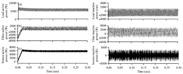 | |
| Fig. 7(a-c): | Instantaneous active and reactive power using APF (a) Load active and reactive power, (b) Filter active and reactive power and (c) Source active and reactive power |
CONCLUSION
APFs are the most effective equipment in power networks that can remove many current harmonic and compensate the reactive power. Instantaneous power theory is one of the best methods which have been described earlier. Afterwards, the hysteresis current control has been clarified with two modes: FBHCC and AHCC. The new method based on modifying and simplifying the AHCC calculation procedure has been demonstrated and simulated. The simulation results proved that proposed technique made the fixed switching frequency that leads to reducing the high frequency components of source current and switching losses as well as faster dynamic response of the controller due to less calculations and short equation in comparison with the AHCC.
REFERENCES
- Akagi, H., Y. Kanazawa and A. Nabae, 1984. Instantaneous reactive power compensators comprising switching devices without energy storage components. IEEE Trans. Ind. Applic., IA-20: 625-630.
CrossRefDirect Link - Bose, B.K., 1990. An adaptive hysteresis-band current control technique of a voltage-fed PWM inverter for machine drive system. IEEE Trans. Industrial Electronics, 37: 402-408.
CrossRef - Singh, B.N., P. Rastgoufard, B. Singh, A. Chandra and K. Al-Haddad, 2004. Design, simulation and implementation of three-pole/four-pole topologies for active filters. IEE Proc. Electr. Power Appl., 151: 467-476.
CrossRefDirect Link - Singh, B.N., B. Singh, A. Chandra and K. Al-Haddad, 2005. Design and digital implementation of active filter with power balance theory. IEEE Proc. Electr. Power Appl., 152: 1149-1160.
CrossRef - Bina, M.T. and E. Pashajavid, 2009. An efficient procedure to design passive LCL-filters for active power filters. Electr. Power Syst. Res., 79: 606-614.
CrossRef - Vahedi, H. and A. Sheikholeslami, 2010. Variable hysteresis current control applied in a shunt active filter with constant switching frequency. Proceedings of the 1st IEEE Conference on Power Quality, September 14-15, 2010, Tehran, Iran, pp: 1-5.
Direct Link - Vahedi, H., Y.R. Kukandeh, M.G. Kashani, A. Dankoob and A. Sheikholeslami, 2011. Comparison of adaptive and fixed-band hysteresis current control considering high frequency harmonics. Proceedings of the IEEE Applied Power Electronics Colloquium, April 19-20, 2011, Johor Bahru, Malaysia, pp: 185-188.
CrossRef - Vahedi, H., A. Sheikholeslami and M.T. Bina, 2011. A novel hysteresis bandwidth (NHB) calculation to fix the switching frequency employed in active power filter. Proceedings of the IEEE Applied Power Electronics Colloquium, April 18-19, 2011, Johor Bahru, Malaysia, pp: 155-158.
CrossRef - Vahedi, H., A. Sheikholeslami, M.T. Bina and M. Vahedi, 2011. Review and simulation of fixed and adaptive hysteresis current control considering switching losses and high-frequency harmonics. Adv. Power Electron., Vol. 2011.
CrossRef - Vahedi, H., E. Pashajavid and K. Al-Haddad, 2012. Fixed-band fixed-frequency hysteresis current control used in APFs. Proceedings of the IECON 2012-38th Annual Conference on IEEE Industrial Electronics Society, October 25-28, 2012, Montreal, QC, pp: 5944-5948.
CrossRef