
Hani Vahedi
Young Research Club, Sari Branch, Islamic Azad University, Sari, Iran
Trends in Applied Sciences Research
Year: 2012 | Volume: 7 | Issue: 2 | Page No.: 151-159


ABSTRACT
Shunt Active Power Filters (APF) are widely used in power systems to eliminate the current harmonics and to compensate reactive power due to their accurate and fast operation. Hysteresis Current Control (HCC) is one of simplest and fastest modulation techniques which is implemented very easily. The practical concern with implementing the Fixed Band Hysteresis Current Control (FBHCC) in APFs is its variable switching pattern which, in turn, results in increasing the risk of occurrence of resonance in power systems and raises the switching losses. To avoid this situation, adaptive HCC (AHCC) methods with the variable hysteresis bands have been recommended in literature. In this paper, a new method in using second band for AHCC has been proposed. The second layer is calculated adaptively as well as the first one. The simulations have been done to demonstrate the efficiency of this method in fixing the switching frequency and reducing THD of source current.
PDF Abstract XML References Citation
Received: November 07, 2011;
Accepted: December 24, 2011;
Published: February 16, 2012
How to cite this article
Hani Vahedi, 2012. Double Band Adaptive Hysteresis Current Control Employed in Active Power Filter. Trends in Applied Sciences Research, 7: 151-159.
URL: https://scialert.net/abstract/?doi=tasr.2012.151.159
URL: https://scialert.net/abstract/?doi=tasr.2012.151.159
INTRODUCTION
Recently, Active Power Filters (APF) have been employed by many researchers and industries to suppress the current harmonics generated by nonlinear loads which has been shown in Fig. 1 (Singh et al., 2005; Emadi et al., 2005). An APF can partially or mostly eliminate the harmonics by injecting the proper compensating current into the power line. A complete compensation will be achieved if the filter generates a current exactly equal in magnitude, but opposite in sign to the harmonic current distortion.
APFs are based on voltage source inverters. The control of APF depends on two major factors: the first is extraction of reference currents and second is the method of generation of Pulse Width Modulation (PWM) signals using these extracted reference currents. The techniques reported in the literature for reference current extraction is instantaneous reactive power theory (Akagi et al., 1984).
The HCC technique is the most suitable PWM method to control APF. The HCC method is characterized by unconditioned stability, swift dynamic performance and notable precision (Kazmierkowski et al., 2002). On the other hand, the conventional fixed-band hysteresis technique (FBHCC) exhibits several undesirable features, such as uneven switching frequency that causes acoustic noise and difficulty in the designing input filters (Bina and Pashajavid, 2009). One of performed methods that can solve this problem is the AHCC method that builds variable band for current tracking, hence the switching speed becomes smooth and the frequency switching will be fixed considerably (Bose, 1990). Also some modifications are reported in literature to improve HCC (Vahedi and Sheikholeslami, 2010; Vahedi et al., 2011a).
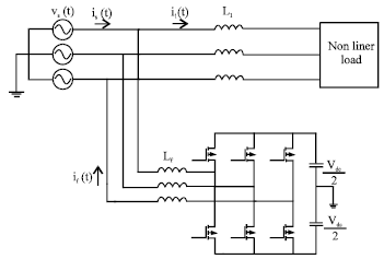 | |
| Fig. 1: | Power system diagram with APF |
In this study, the instantaneous power theory has been explained to extract the harmonics components of current waveform. Then, the FBHCC and AHCC have been clarified. Afterwards, the proposed method in using the second adaptive band has been described. Finally, some simulations have been done with MATLAB/Simulink and the results consist of switching frequency diagrams and current THD have been discussed. By comparing the results of simulations, the advantages of AHCC in fixing switching frequency and modifying above mentioned problems, have been shown. The better results are achieved when the second layer is used in simulations.
INSTANTANEOUS POWER THEORY
The initial step in eliminating the load current harmonics and imbalance is extraction of the compensation reference currents. Then, the derived reference signals should be produced by employing precise switching modulation of voltage source inverter. Eventually, through connecting inductances or other low-pass passive filters, the generated filtering currents should be injected in the grid to compensate efficiently the harmonics and imbalance.
One of the popular compensation reference current extraction methods is the instantaneous reactive power theory (p-q theory) presented by Akagi et al. (1984). Although, there are some problems with this theory, it is well-established and simple in implementation. The p-q theory could be briefly reviewed as follow (Akagi et al., 1984).
Assume a three-phase load with the instantaneous voltages as v(t) = [va(t) vb(t) vc(t)]t and the instantaneous currents as il(t) = [ila(t) ilb(t) ilc(t)]t (Fig. 1). Using (1), v(t) and il(t) can be converted to o-a-ß coordination where C is the matrix (2):
| (1) |
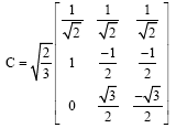 | (2) |
Let’s assume that the zero sequence current (il0(t)) is null. Thus, the instantaneous active (p(t)) and reactive (q(t)) powers can be calculated as:
| (3) |
where, p(t) and q(t) can be decomposed to the average parts (![]() ) and the oscillating parts (
) and the oscillating parts (![]() ). It is notable that
). It is notable that ![]() is produced by the fundamental harmonic of the positive sequence component of the load current. Therefore, in order to compensate the harmonics and the instantaneous reactive power, compensation reference currents can be extracted as follow:
is produced by the fundamental harmonic of the positive sequence component of the load current. Therefore, in order to compensate the harmonics and the instantaneous reactive power, compensation reference currents can be extracted as follow:
| (4) |
| (5) |
HYSTERESIS CURRENT CONTROL
Hysteresis current control is used for generating the switching pulses. Among the various current control techniques, HCC is the most extensively used technique because of the noncomplex implementation, outstanding stability, absence of any tracking error, very fast transient response, inherent limited maximum current and intrinsic robustness to load parameters variations. As indicated in literatures a review of used current control techniques for PWM converters reveals that HCC shows certain superiority for active power filter applications. HCC provides a better low-order harmonic suppression than PWM control which is the main target of the active power filter. It is easier to realize with high accuracy and fast response. However, as a disadvantage its switching frequency might fluctuate.
In the HCC technique the error function is centered in a preset hysteresis band. When the error exceeds the upper or lower hysteresis limit the hysteretic controller makes an appropriate switching decision to control the error within the preset band and send these pulses to VSI to produce the reference current as shown in Fig. 2.
The outputs of the hysteresis blocks are directly fed as the firing pulse of VSI switches.
Fixed-band hysteresis current control (FBHCC): In fixed-band HCC, the Hysteresis Bandwidth (HB) has been taken as a small portion related to system current and in many researches it has been taken as 5% of main current which will be HB = 0.9 A, here.
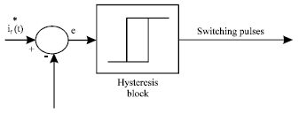 | |
| Fig. 2: | Fixed-band hysteresis current control loop |
 | |
| Fig. 3: | Single- phase diagram of a power system with APF |
Adaptive hysteresis current control (AHCC): As above-mentioned, the crucial concern with the fixed band hysteresis current control is producing a varying modulation frequency of the power converter which, in turn, results in increasing the switching losses. To avoid this situation, adaptive hysteresis current controller methods with the variable hysteresis band have been recommended in literature (Bose, 1990; Vahedi et al., 2011b). Hence, a variable hysteresis band is defined for each phase so that the switching frequency remains almost constant. Figure 3 presents Single- phase diagram of a power system with APF.
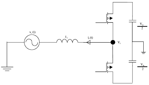
The variable HB formula can be calculated based on Fig. 1. The following KVL equation can be easily achieved:
| (6) |
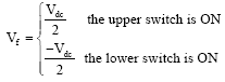
where, Vf is the inverter-side voltage and can be elaborated as below:
 | (7) |
Having paid attention to Fig. 4, the below relations can be obtained:
| (8) |
| (9) |
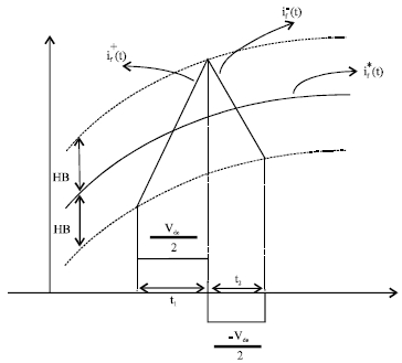 | |
| Fig. 4: | The upper and lower bands of the reference compensation current |
where, t1 and t2 are the rising current and the falling current, respectively. Furthermore, the following relations can be extracted:
 | (10) |
| (11) |
where, t1 and t2 are switching intervals and f is the switching frequency.
By substituting (8) (9) and (11) in (10), the hysteresis band (HB) can be achieved as follow:
| (12) |
The adaptive HB should be derived instantaneously during each sample time to keep the switching frequency constant.
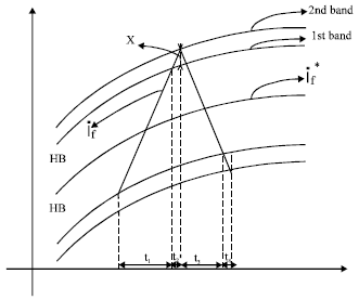
Second band calculation: As it is clear in HCC, sometimes the wave in the band will go out of it, so there are differences in actual time of touching the band and acting of switches. This difference is due to the delay between ordering the switches and their real action which is shown in Fig. 5.
As it is clear, there are some intervals between ordering a switch and its action. It is shown in Fig. 6. These intervals are inevitable due to filter inductance and switches’ performances.
 | |
| Fig. 5: | Violating of signal in hysteresis band |
 | |
| Fig. 6: | Double band in hysteresis current control |
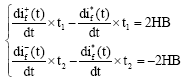
Therefore, to deal with these intervals, the bandwidth (x) produces thorough them will be calculated. The main concern in this technique is calculating the second bandwidth (x) adaptively. So this can be written as follows:
| (13) |
| (14) |
where, t2 is the real action time of a switch. It means the time that switch is fired and then it gets closed or opened. This is the working frequency of the switch. In this project, as the MOSFET has been used, their frequencies are up to 100 KHz. So if the second band varies through the Eq. 14, the better results will be gained in THD and switching frequency.
SIMULATION RESULTS
To verify validity of the proposed method some simulations are done using MATLAB/Simulink. The nonlinear load consists of a three-phase diode rectifier with a DC-side resistive load. It should be mentioned that the nonlinear load is connected to the grid via inductances (Lf = 4 mH).
 | |
| Fig. 7: | The currents for phase (a) |
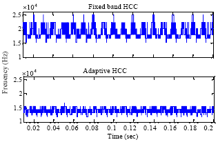 | |
| Fig. 8: | Instantaneous switching frequency for FBHCC and AHCC |
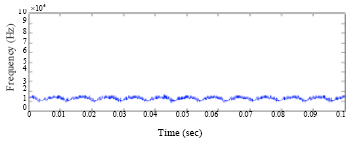 | |
| Fig. 9: | Instantaneous switching frequency for double band method |
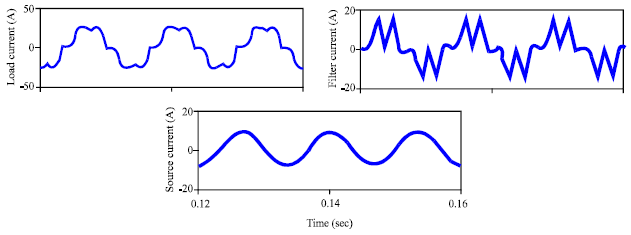
Besides, the load voltages have an rms value of 155 V-50 Hz leads to rms value of 18 A for system current.
The source voltage has been remained sinusoidal and does not contain any harmonics. Figure 7 shows diagrams of load current, filter current and source current respectively for this simulation. These diagrams show a good filtering leads to eliminate the source current harmonics, so the source current contains just the main component. APF simulation parameters are presented in Table 1.
The THD results in Table 2 show that proposed method works properly to track the reference current and there was a good filtering process. But the Fig. 8 and 9 show the difference between three techniques. The AHCC distinction will be proved by Fig. 8 and 9.
| Table 1: | APF simulation parameters |
 | |
| Table 2: | THD% value of load and source currents |
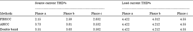 | |
As it is observed in Fig. 8 and 9, the switching frequency of FBHCC varies in a wide range leads to high switching losses and audio noise, but AHCC fixed this issue. On the other hand the proposed method smoothed the switching frequency curve so there is not any maximum or minimum peaks unlike the AHCC diagram. This result influences the source current THD especially in high frequency range. Since the variation range of switching frequency has been limited to small domain, the high frequency components of source current have been reduced to a narrow range.
The vast range of high frequency components of current harmonic is just a source for audio noises as well as producing switching losses due to the switch resistance. Each harmonic order should be multiplied by the square of the switch resistor to obtain the power losses so in FBHCC this value is higher than others.
CONCLUSION
Shunt active power filters are the most suitable devices in power networks eliminate the current harmonics and compensate the reactive power. Instantaneous power theory is one of the effective methods which has been explained in this paper. Afterwards, the hysteresis current control has been clarified with two modes: FBHCC and AHCC. The new method based on assuming a second band which varies adaptively for HCC smoothies the switching speed results in fixer switching frequency. The simulation results proved that proposed technique made the fixed switching frequency that results in reducing the high frequency components of source current and switching losses.
REFERENCES
- Bose, B.K., 1990. An adaptive hysteresis-band current control technique of a voltage-fed PWM inverter for machine drive system. IEEE Trans. Industrial Electronics, 37: 402-408.
CrossRef - Singh, B.N., B. Singh, A. Chandra and K. Al-Haddad, 2005. Design and digital implementation of active filter with power balance theory. IEEE Proc. Electr. Power Appl., 152: 1149-1160.
CrossRef - Bina, M.T. and E. Pashajavid, 2009. An efficient procedure to design passive LCL-filters for active power filters. Electr. Power Syst. Res., 79: 606-614.
CrossRef - Vahedi, H., A. Sheikholeslami and M.T. Bina, 2011. A novel hysteresis bandwidth (NHB) calculation to fix the switching frequency employed in active power filter. Proceedings of the IEEE Applied Power Electronics Colloquium, April 18-19, 2011, Johor Bahru, Malaysia, pp: 155-158.
CrossRef - Vahedi, H., A. Sheikholeslami, M.T. Bina and M. Vahedi, 2011. Review and simulation of fixed and adaptive hysteresis current control considering switching losses and high-frequency harmonics. Adv. Power Electron., Vol. 2011.
CrossRef - Akagi, H., Y. Kanazawa and A. Nabae, 1984. Instantaneous reactive power compensators comprising switching devices without energy storage components. IEEE Trans. Ind. Applic., IA-20: 625-630.
CrossRefDirect Link