
Mazin M. Al Hadidi
Department of Computer Engineering, Faculty of Engineering, Al Balq�a Applied University, Jordan
Yasir Khalil Ibrahim
Department of Computer Science, Faculty of Science, Jerash Private University, Jordan
Trends in Applied Sciences Research
Year: 2008 | Volume: 3 | Issue: 2 | Page No.: 165-173


ABSTRACT
In this study, an electromechanical, renewable energy resources of solar; two axes sun-tracking system designed and constructed. A closed loop system employed for control part. A Programmable Integrating Circuit (PIC) used to control the motion of the sun-tracking surface with photovoltaic (PV) panels. The feedback analog signal coming from FV through a variable resistor was controlling scanning sequence. First, scan to the right and left by the secondary motor and second scans in the forward and backward directions by the major motor. Another two potentiometers are used; one for detects the sun availability and the other to measure the batteries fulfillment. The relay switch biased by a power transistor used to control the batteries charging process.
PDF Abstract XML References Citation
How to cite this article
Mazin M. Al Hadidi and Yasir Khalil Ibrahim, 2008. Renewable Energy Resources, Study Case for Jordan. Trends in Applied Sciences Research, 3: 165-173.
URL: https://scialert.net/abstract/?doi=tasr.2008.165.173
URL: https://scialert.net/abstract/?doi=tasr.2008.165.173
INTRODUCTION
Due to the earth’s constant motion, fixed photovoltaic panels intercept far less sunlight than they could. Therefore, they produce much less power than the possible maximum. Such panels could be oriented in varying degrees to track the sun to increase their power output. Two axes tracking system is well suited to be used with photovoltaic (PV) panels to improve their performance, which could also be employed in systems that use concentrating and flat plate collectors such as those used for residential space cooling and heating systems.
Jordan imports most of its energy demands in the form of crude oil and petroleum products. This is causing a big burden on the national economy due to the lack of conventional resources. The problem expected to get worst since Jordan’s demand for energy is growing at a rate of 5.2% per Annum. To meet the country’s future energy demands requires a long-termed plan based on a sell-defined strategy, covering the next two or three decades part of this plan would be to utilize Jordan’s renewable energy resources like solar energy. Currently the share of renewable energy in the total energy consumption is around 1%. It has expected that with increasing the scientific and techno logical capacities in the field of renewable energy in Jordan, this share will use up to 15% in the year 2010. Jordan is blessed with an excellent solar energy resources in the desert region which covers more than 80% of the country, the average global solar radiation on horizontal surface is 5500 whm2 and the average bright sunshine is (3000/365) h.
The solar time divided into four intervals during the day with respect to these two angles as shown in Fig. 1.
There are three types of silicon solar cells; Single Crystal solar cells in panel, Polycrystalline solar panel and amorphous solar panel. To understand the operation of a PV cell, we need to consider both the nature of the semiconductor and the nature of sunlight. Solar cells consist of two types of semiconductor, often p-type silicon and n-type silicon. Light of certain wavelengths is able to ionize the atoms in the silicon and the internal field produced by the junction separates some of the positive charges (holes) from the negative charges (electrons) within the photovoltaic device.
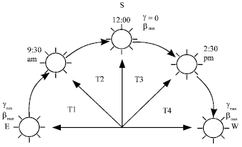 | |
| Fig. 1: | The division of daylight time into four intervals |
The holes are swept into the positive or p-layer and the electrons are swept into the negative or n-layer. Although these opposite charges attracted to each other, most of them can only recombine by passing through an external circuit outside the semiconductor because of the internal potential energy barrier. Therefore, if a circuit made (Fig. 2) power produced from the cells under illumination, since the free electrons have to pass through the load to recombine with the positive holes.
The amount of power available from a PV device is determined by; the type and area of the semiconductor, the intensity of the sunlight and the wavelength of the sunlight.
Few theoretical and experimental studies cited in the literature, which investigates various types of tracking systems.
Odeh and Morrison (2001), presented a theoretical comparative study between the energy available to a two-axis tracker, an east-west tracker and a fixed surface. They found that the energy available to the ideal tracker is higher by 3-12 and 60% than the east-west tracker and the fixed surface, respectively. Yousef (1999), presented a sun tracking system for use with various collectors using fuzzy logic techniques, which enabled the sun’s position to be resolved to a precision of better than 0.1°. Baltas et al. (1986) made a comparative study between continuous and stepwise tracking. They showed that unlike concentrating systems, flat plate photovoltaic arrays yielded almost the same amount of energy when tracking in a stepwise fashion. Tracking motors could be idle for one or two hours and yet obtain more than 98% of the energy obtained from a continuous tracking array. Brunotte et al. (1996) presented a prototype two-stage PV concentrator with concentration ratios up to 300X with one axis tracking. Such concentrators are very promising in reducing the cost of solar electricity conversion. Some studies indicate that electric energy production costs for concentrating PV plants are about one-third of those of flat module plants (Barakat et al., 2001). Khalifa and AL-Mutawalli (1998) performed an experimental study to investigate the effect of using a two-axis sun-tracking system on the thermal performance of compound parabolic concentrators. Tracking achieved using two phototransistors. The tracking compound parabolic concentrators showed a better performance with an increase in the collected energy of up to 75% compared with an identical fixed collector.
Abdullah and Nijmeh (2001) designed a single axis sun tracking system with Programmable Logic Controller (PLC) in three modes of operation; rotation about east-west, north-south and vertical axes. The daily measured solar energy increased by up to 19.7, 23.3 and 24.5% for the north south, vertical and east west tracking respectively, as compared with 32° inclination to the south.
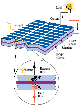 | |
| Fig. 2: | The photovoltaic effect in a solar cell |
Barakat et al. (2001) designed a two axes sun tracking system with closed loop control based on the complicated typical electronic circuit. They found that the energy available to the two axes tracker is higher by 20%. Abdullah and Nijmeh (2004) designed a two axes sun tracking system with open loop control based on PLC system. The two axes tracking surface showed a better performance with an increase in the collected energy of up to 41.3% compared with the fixed surface. Abdullah (2004a) performed an experimental study to investigate the effect of using different types of sun tracking systems on the voltage-current characteristics and electrical power generation at the output of flat plate photovoltaic (FPPV). The results indicated that the volt-ampere characteristics on the tracking surfaces were significantly greater than that on a fixed surface. There were a rise of electrical power gain up to 43.8, 37.5, 34.4 and 15.7% for the 2 axes, east west, vertical and north-south tracking respectively, as compared with the fixed surface inclined 32° to the south in Amman, Jordan. Abdullah (2004b) studied the effect of utilization of various types of automatic sun tracking modes on the performance of water pumping systems, which power supply is FPPV. The study concluded that the two axes tracking system was the most effective in water pumping, this system showed an increase of pumping efficiency up 50% compared to fixed surface with 32° inclined to the south. On the other hand, the results of the east-west system, vertical and north south showed a net gain of pumping rate for 40, 32 and 20%, respectively.
SYSTEM DESCRIPTION
Introduction to Two Axes Sun Tracking System
Due to the earth’s constant motion, fixed photovoltaic panels intercept far less sunlight than they could. Therefore, they produce much less power than the possible maximum. Such panels could be oriented in varying degrees to track the sun to increase their power output (Shinni and Rumala, 1986). Two axes tracking system is well suited to be used with photovoltaic (PV) panels to improve their performance, which could also be employed in systems that use concentrating and flat plate collectors such as those used for residential space cooling and heating systems.
Theory
For a plane that is continuously tracing about two axes to minimize the angle of incidence (Zogbit and Laplaze, 1984):
| (1) |
where:
θ= The angle of incidence.
| (2) |
where:
β= The slope Angle
θZ= Zenith angle.
| (3) |
This theory means that we must make the surface angles (β, γ) equal the solar angles (θ2, γS).
For horizontal surface the slope angle (β) is the Zenith angle θZ and its valve must be between (0° - 90°), (β = 0 when the sun is above the horizon):
| (4) |
where:
| θZ | = | The Zenith angle |
| ø | = | Latitude angle (For Amman 32°) |
| δ | = | Declination angle |
| ωS | = | Hour angle |
where the declination found from the equation.
| (5) |
Moreover, n is the day of years and obtained from tables.
The solar Azimuth angle γS can have values in the range of 180°-180°.
| (6) |
where:
| (7) |
where:
| ω | = | Hour angle |
| δ | = | declination angle (From Eq. 5) |
i- Latitude angle (Form Amman 32°)
 | (8) |
| (9) |
| (10) |
where:
| δ | = | declination angle (Eq. 5 |
| i | = | Latitude angle (For Amman 32°) |
The calculation of ω (hour Angle)
| (12) |
where:
| ωS | = | Sun set hour angle when θZ = 90 |
| ω | = | -ωS (sun rise) |
| ω | = | +ωS (sun set) (- ω before noon = ω after noon) symmetrical. |
The number of day light hours is from equation.
where, ωS from Eq. 12.
The time that the sun rise and symmetrical the time of the sunset can found from
Sample of Calculations
For date is 20/12, the day = 20
n = from tables = 334 + 20 = 345
δ= 23.45 sin
δ= -23.45°
(ωew From Eq. 11):= cos-1 (tan δ/tan ø)
ωew= cos-1 (tan(-23/45)/tan(32))
ωew= 132.96°
(ω From Eq. 12):
ωS= cos-1 (-tanø tanδ)
ωS= cos-1 (-tan (32) tan (-23.45))
ωS= +74.27°
w= + ωS (at sunset)
w= - ωS (at sunrise).
w (at sunset)= 74.27°
w (at sunrise)= -74.27°
β From Eq. 2 β = θZ
θZ from Eq. 4
θZ = cos-1 (cosø cosδ cosω + sin ø sinδ)
θZ = cos-1(cos32 cos-23.45 cos-74.27 +sin 32 sin -23.45)
β = θZ = 90° (maximum)
γ from equation 3 γ = γS
γS from Eq. 6
γS = C1C2γS' + C3
γS' from Eq. 7
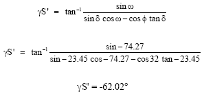 |
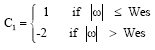
C1 From Eq. 8
C1 = 1, 1-74.27 < 133.96
C2 From Eq. 9
C2 =1, (ø-δ) ≥ 0, (32-(-23.45) ≥ 0
(55.45) > 0
C3 = -1, ω < 0 → -74.27 < 0
From Eq. 10
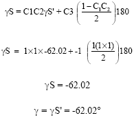 |
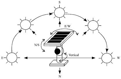 | |
| Fig. 3: | Two axes sun-tracking system |
Two tracking motors are used, one for the joint rotated about the horizontal north-south axis to control the angle β and the other motor for the joint rotated about the east-west axis to control the angle γ (Fig. 3).
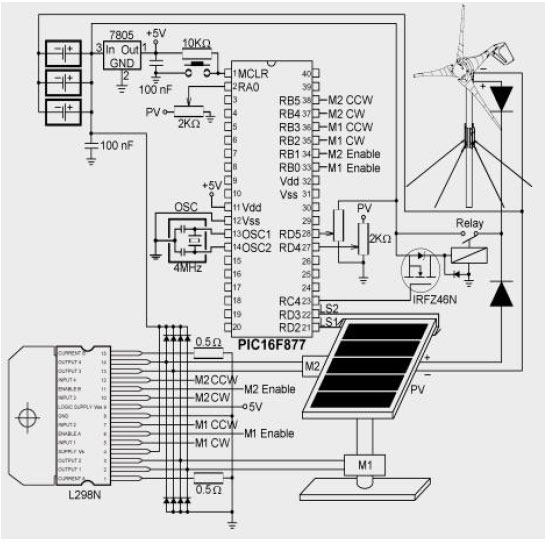
Electromechanical System Description
The PV used to discriminate the sun’s position and to send electrical signals proportional to the error to the controller, which actuates the motors to track the sun. The compact and lightweight actuator represents a drive system:
| • | PV solar array. |
| • | Air wind turbine generator. |
| • | Two driving motors. |
| • | PIC Microcontroller PIC16F877. |
| • | Driver. |
| • | Switch relay. |
| • | Switch limits. |
| • | UPS batteries. |
| • | Diods. |
| • | Potenimater. |
| • | Oscillatoer, regulator, resistors, capacitors, wires . |
The PIC16F877 mid range family microcontroller is used to control the sun tracking system motors and the energy collection from PV cells and wind turbine. The PIC microcontroller has a programmable memory in which instructions were stored to implement various functions used to control the actuation of the tracking motors function of the sun position and to control the energy stored in the Uninterruptible Power Supply (UPS) batteries.
Controller Circuit Power Supply
The correct voltage supply is of utmost importance for the proper functioning of the microcontroller system. For a proper function of any microcontroller, it is necessary to provide a stable source of supply. According to technical specifications by the manufacturer of PIC microcontroller, supply voltage should move between 2.0 to 6.0 v in all versions. The simplest solution to the source of supply is using the voltage stabilizer LM7805 (Fig. 4) that gives stable +5V on its output.
 | |
| Fig. 4: | System layout |
System Oscillator
The oscillator circuit used to generate the Microcontroller device clock. The device clock is required for the device to execute instructions and for the peripherals to function. Four device clock periods generate one internal instruction clock (TCY) cycle. There are two modes which allow the selection of the internal RC oscillator clock out (CLKOUT) to be driven on an I/O pin, or allow that I/O pin to be used for a general purpose function. The device configuration bits select the oscillator mode.
System Reset
The reset logic used to place the device into a known state. The source of the reset can be determined by using the device status bits. The reset logic designed with features that reduce system cost and increase system reliability. PIC micro differentiates between various kinds of External/Internal and Hardware/Software reset; POR Power ON Reset,/MCLR reset during normal operation,/MCLR reset during SLEEP mode, WDT reset during normal operation.
CONCLUSIONS
From the results, we conclude that the solar energy fully controlled by a PIC Microcontroller for collecting the sunlight energy or for organize batteries charging process. Those results, as well, affected by the weather and controlled by tracking process. Because of low photovoltaic sensitivity; the feedback control signal is not effective to control the scanning process and to increase the sun tracking process sensitivity; we must replace the photovoltaic feedback signal by a signal coming from a sensitive sun-tracking sensor. Another factor affecting the sunlight collected energy is the scanning range in the major axes is not full 180° ranges due to the motor actuator fixtures. In addition, to improve this point we must modify our mechanical design and replace motors especially the motor for major axis or east-west axis movements.
The batteries power level is almost constant forever in reason of slow discharging process and the closed loop control for recharging process.
Moreover, with such energy we find this kind of it useful is a pollution-free, infinitely sustainable form of energy. It does not use fuel; it does not produce greenhouse gasses and it does not produce toxic or radioactive waste. Moreover, the most important feature of this energy it is and endless one that is not like another energy producers some day will be vanish like fuel.
REFERENCES
- Abdullah, S., 2004. The effect of using sun tracking systems on the voltage-current characteristics and power generation of flat plate photovoltaic. Energy Converts Manage., 45: 1671-1679.
Direct Link - Abdullah, S. and S. Nijmeh, 2004. Two axes sun tracking system with PLC control. Energy Convers. Manage., 45: 1931-1939.
Direct Link - Baltas, P., M. Tortoreli and P. Russel, 1986. Evaluation of power output for fixed and step tracking photovoltaic arrays. Solar Energy, 37: 147-163.
CrossRefDirect Link - Brunotte, M., A. Goetzberger and U. Blieske, 1996. Two-stage concentrator permitting concentration factors up to 300x with one-axis tracking. Solar Energy, 56: 285-300.
CrossRef - Khalifa, A.N. and S.S. Al-Mutwalli, 1998. Effect of two-axis sun tracking on the performance of compound parabolic concentrators. Energy Converse Manage., 39: 1073-1079.
Direct Link - Odeh, S.D. and G.L. Morrison, 2005. Optimization of parabolic trough solar collector system. Int. J. Energy Res., 30: 259-271.
Direct Link - Yousef, H.A., 1999. Design and implementation of a fuzzy logic computer-controlled sun tracking system, industrial electronics. Proc. IEEE Int. Symp., 3: 1030-1034.
CrossRef - Zogbi, R. and D. Laplaze, 1984. Design and construction of a sun tracker. Solar Energy, 33: 369-372.
Direct Link