
Hao Chen
College of Automotive Engineering, Shanghai University of Engineering Science, Shanghai, 201620, China
Yali Yang
College of Automotive Engineering, Shanghai University of Engineering Science, Shanghai, 201620, China
Journal of Software Engineering
Year: 2015 | Volume: 9 | Issue: 4 | Page No.: 868-876


ABSTRACT
Electric Power Steering (EPS) is a full electric system, which reduces the amount of steering effort by directly applying the output from an electric motor to the steering system. This study aimed at developing EPS boost curve embody into the assist characteristics, improving steer portability and stability. A model for the EPS system had been established, including full vehicle mechanical system, EPS mechanical system and EPS electric control system. Based on this model, a straight line boost curve was designed and evaluated in this environment to improve the performance of EPS system. Based on the designed curve, EPS control model was established by integrating ADAMS and MATLAB. The co-simulation system was applied to evaluate the performance of EPS system. Simulations were conducted under double lane change and returning condition. Even with preliminary study, results showed that the designed curve under PID control can provide higher performance in control stability, which indicated the positive effect of designed EPS boosting curve on higher vehicle performance.
PDF Abstract XML References Citation
Received: October 25, 2014;
Accepted: March 03, 2015;
Published: April 25, 2015
How to cite this article
Hao Chen and Yali Yang, 2015. Study on Electric Power Steering System based on ADAMS and MATLAB. Journal of Software Engineering, 9: 868-876.
DOI: 10.3923/jse.2015.868.876
URL: https://scialert.net/abstract/?doi=jse.2015.868.876
DOI: 10.3923/jse.2015.868.876
URL: https://scialert.net/abstract/?doi=jse.2015.868.876
INTRODUCTION
Electric Power Steering (EPS) is an all-electric, engine-independent system that uses an electric motor to provide power steering assist. Electric Power Steering (EPS) system is a very important component for improving automotive handling and stability (Schoner and Hille, 2000). Since the EPS system is an on-demand system that operates only when the steering wheel is turned, the fuel efficiency of a vehicle equipped with such system is up to 3% better than that of vehicles equipped with an equivalent-output hydraulic system (Xue-Ping et al., 2009). As a result, the EPS system is more energy efficient and environmentally compatible.
An EPS system includes mechanical subsystem and electronic and control subsystem and it has to work in the full vehicle mechanical system. In the development process of the EPS system, different subsystems have to be developed in parallel so as to reduce time and cost of system development. Cooperation between engineers for developing different subsystems is also needed. Liao et al. (2003) developed a full vehicle model integrated with an EPS control system algorithm and predicted the dynamic behavior of an EPS-equipped vehicle resulting from steer and road input. Kim and Song (2002) investigated the EPS control system logic for the reduction in steering torque, the realization of various steering feels and the improvement of return-to center performance. Therefore, a model-based development is a rational way for this parallel developing and cooperation (Wu, 2007; Kurishige et al., 2000; Norman, 1984).
One of the most important parts of the EPS system is the electric control system, which receives signals collected by sensors for vehicle speed, steering angle, steering torque and controls the assistant motor for giving required assistant torque. The key of this control system is to find a boosting curve to embody the assist characteristic. Most researchers of EPS emphasized on the control strategy. Few of assist characteristics was studied. In Chabaan and Wang (2001), a boost curve was given but without calculation formula. Zaremba et al. (1997, 1998) studied the steering assist value just from road feel.
A model-based development method for EPS system has been explored. A model for the EPS system has been established in a full vehicle mechanical system environment. A straight line boost curve was designed and the related control system including ADAMS and MATLAB was established. Co-simulation was conducted to evaluate the performance of designed EPS system.
MODELING
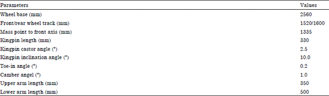
Full vehicle model: The system-level model included a mechanical subsystem model for a full vehicle and for steering system in detail. This mechanical model for the full vehicle and the steering system was established in the software MSC.ADAMS. Table 1 was the main orientation parameter for the model.
It included suspensions for the four corners. The steering system’s mechanical model included steering wheel, steering column, steering rack/pinion and some connection poles. The chassis model was coupled with the road surface by tire model, which was built based on the MSC.ADAMS/TIRE module with P215/80R16 radial tire. The full vehicle model was shown in Fig. 1. The model consisted of 15° of freedom, including 6 for vehicle body, 2 for front suspension, 2 for rear suspension, 4 for wheels and 1 for steering wheel.
EPS model: The EPS subsystem model was described by the angular rate and position of the steering column and motor, the linear velocity and displacement of the steering rack. Figure 2 was the schematic diagram of a steering mechanism equipped with EPS.
It can be formally subdivided into three subsystems: (1) Mechanical steering system consisting of steering wheel, steering column, torsion bar and steering rack, (2) Brush-type Direct Current (DC) motor, which provides assisting torque and (3) Electronic Control Unit (ECU) with related sensors, such as steering torque, steering angle sensor and motor current sensor.
The principal mode of operation can be summarized as follows. If driver turns the steering wheel, the torsion bar is twisted and a steering torque is generated, which in turn moves steering rack.
| Table 1: | Main orientation parameters for vehicle model |
 | |
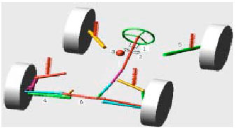 | |
| Fig. 1: | Full vehicle’s mechanical system model |
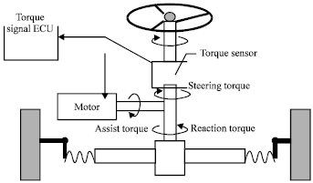 | |
| Fig. 2: | A steering mechanism with EPS |
The change of the vehicle direction depends on the change of steering rack position, which causes the change of the rack force. In order to assist driver and provide a good steering feeling, a certain amount of rack force is compensated by the servo force generated by assistant motor.
DESIGN OF BOOST CURVE
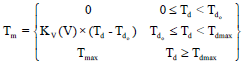
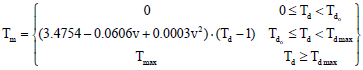
The power-assisted characteristic of EPS has curves of sorts. Figure 3 shows three kinds of typical power assisted characteristic curves of EPS. Each characteristic curve can be divided into three areas: 0≤Td<Tdo is no power-assisted area, Tdo≤Td<Tdmax is the changing area of power-assisted and Td≥Tdmax is the fixed area.
Among the three kinds of power-assisted characteristic curves, the straight-line boost curve is the most widely used one. The assist torque is proportional to the torque of steering wheel. Thus, road feel intensity is a constant, which is convenient to design and adjust the control system easily. The assist torque for straight line type is calculated as in Eq. 1:
 | (1) |
where, Tm is assist torque, Td is steering wheel torque, Tdo is steering wheel torque when assist torque begin to generate, Tdmax is the steering wheel torque when maximum assist torque is applied, KV(V) is assist coefficient, Tmax is the maximum torque for steering wheel.
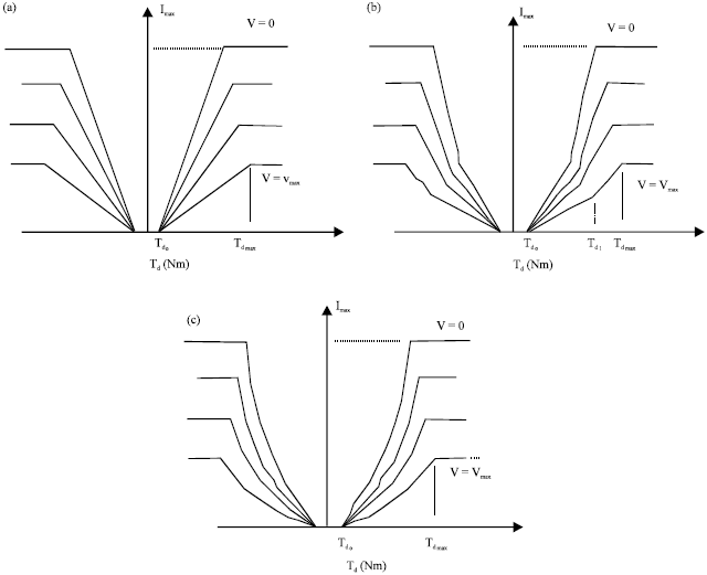 | |
| Fig. 3(a-c): | Typical power-assisted characteristic curve of EPS, (a) Straight line type, (b) Broken line type and (c) Curve type |
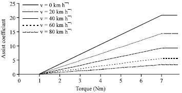
Tdo and Tdmax are related to the feeling of driver. Thus, their values can be obtained by experiment, on the basis of steering portability and road feel. According to Chen et al. (2010), assist torque generated for cars when Tdo = 1.0 Nm, while the maximum assist torque Tdmax is 7.0 Nm.
Based on the model established, the maximum torque for steering wheel was gained through simulation:
| • | Assist torque when velocity is 0 km h-1 |
The maximum assist torque under 0 km h-1 velocity can be calculated by Eq. 2:
| (2) |
where, Trmaxo is the maximum steering resistance force when velocity was 0 km h-1, which can be calculated by Eq. 3:
 | (3) |
where, f is coefficient of sliding friction, G1 is load for the front axle, P is tire pressures, i is steering gear angle ratio, η is the efficiency of steering gear.
According to the vehicle model, front axle load G1 was 5300N, tire pressure P was 0.3 MPa, angle ratio i was 20 and efficiency was 90%, thus Trmaxo = 28.1 Nm. Therefore, the maximum assist torque was 21.1N.
| • | Assist torque when velocity is 20, 40, 60, 80 and 100 km h-1 |
The torque of steering wheel was recorded by rotating uniformly to one side limit position, under the velocity of 20, 40, 60, 80 and 100 km h-1. The maximum value for each velocity represented its Tmax, shown in Table 2.
The assist torque range is 1.0 to 7.0 Nm. Therefore, the assist torque in this range can be obtained by using interpolation methods. The assist torque can be calculated by Eq. 4:
| (4) |
Taking all these values into the above equations, the assist coefficient KV(V) was calculated under different velocities, shown in Table 1.
Along with the increase in velocity, the value of assist coefficient was reduced. When velocity was 100 km h-1, Tmax<Tdmax, there was no need for assist torque.
Boosting curve: By using polynomial regression, the assist coefficient was obtained:
| (5) |
Therefore, the straight line boost curve can be established, shown in Fig. 4:
| Table 2: | Maximum steering wheel torque and assist coefficient under different velocities |
 | |
 | |
| Fig. 4: | Straight line boost curve under different velocities |
 | |
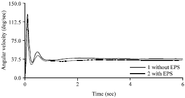
| Fig. 5: | Angular velocity curve with and without EPS |
 | |
| Fig. 6: | EPS control system model |
 | (6) |
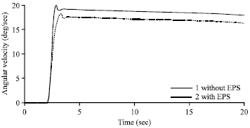
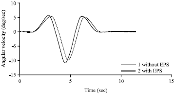
Simulation: Based on the designed straight line boosting curve, simulation experiment was done to illustrate its effect on assist characteristics. Angle step function response experiment was done in ADAMS software. The initial velocity was 80 km h-1. The input was 100° angle step. Output was the angular velocity of the whole vehicle, which can show the stability of vehicle. Simulation result with and without EPS were shown in Fig. 5. As time went by, angular velocity for the curve without EPS system was obviously higher than that with EPS system using the straight line boosting curve. Both reacting time and overboost value reduced when using straight line boost curve EPS system, which can ensure the dynamic reaction and stability when car was moving.
CO-SIMULATION BASED ON ADAMS AND MATLAB
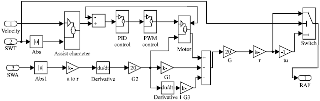
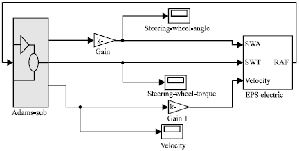
Control system: Based on the spline function AKISPL, the designed straight line boosting curve was used as SPLINE using velocity and steering wheel torque interpolation. PID control was used in EPS control model, which can achieve smooth response of reaction torque (Li et al., 2009). EPS control mode was established as shown in Fig. 6. Then the adams_sbu system and EPS control model were integrated to establish the co-simulation control system, shown in Fig. 7.
Simulation and analysis: Double lane change simulation was done according to (GB/T 6323.5-94, 1994). The velocity was 80 km h-1, then start double lane change to evaluation the control stability.
 | |
| Fig. 7: | ADAMS and MATLAB co-simulation system diagram |
 | |
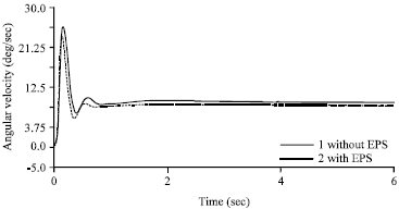
| Fig. 8: | Angular velocity in double lane change |
 | |
| Fig. 9: | Steering wheel angle change |
Figure 8 showed the angular velocity change in double lane change. Simulation showed that the maximum angular velocity was reduced when using designed straight line boosting curve with PID control, which indicates the positive effect of EPS system on control stability.
Return ability simulation was conducted under (GB/T 6323.4-94, 1994) criterion. Car moved on circle with 15 m radius. The lateral acceleration was adjusted to 4 m sec-2. Then free the steering wheel. The front wheel will return to straight line under the effect of aligning torque. Figure 9 and 10 illustrated that the steering wheel angel and yaw velocity along with time change, respectively.
 | |
| Fig. 10: | Steering wheel angular velocity change |
In both steering wheel angle and angular velocity, system with EPS reduced returning time and showed higher returning ability, which indicated that EPS system had positive impact on vehicle control stability.
CONCLUSION
On the basis of whole-vehicle model, the straight line type boost curve was designed and its validation was ensured. The corresponding control system was also established by using ADAMS and MATLAB. Simulation was conducted in double lane change and returning condition. The preliminary results showed that the designed EPS system improved performance of steering wheel angle and angular velocity, thus ensures the dynamic reaction and stability when car was moving, which indicated the positive effect of designed EPS system on vehicle control stability. More comparison studies should be included further to improve the results and further research is under way on improvement of control strategy on EPS system to accomplish higher performance of EPS system.
ACKNOWLEDGMENTS
This study is supported by Shanghai Municipal Education Commission project (13YZ109). The financial support is gratefully acknowledged.
REFERENCES
- Chabaan, R.C. and L.Y. Wang, 2001. Control of electrical power assist systems: H∞ design, torque estimation and structural stability. JSAE Rev., 22: 435-444.
CrossRefDirect Link - Chen, H., Y.L. Yang and L.H. Chen, 2010. Study on boosting curve for electric power steering system based on ADAMS. Adv. Mater. Res., 97: 3308-3313.
CrossRefDirect Link - Kim, J.H. and J.B. Song, 2002. Control logic for an electric power steering system using assist motor. Mechatronics, 12: 447-459.
CrossRefDirect Link - Li, X., X.P. Zhao and J. Chen, 2009. Controller design for electric power steering system using TS fuzzy model approach. Int. J. Autom. Comput., 6: 198-203.
CrossRefDirect Link - Liao, Y.G. and H.I. Du, 2003. Modelling and analysis of electric power steering system and its effect on vehicle dynamic behaviour. Int. J. Veh. Autonom. Syst., 1: 153-166.
Direct Link - Schoner, H.P. and P. Hille, 2000. Automotive power electronics. New challenges for power electronics. Proceedings of the 31st IEEE Annual Power Electronics Specialists Conference, Volume 1, June 18-23, 2000, Galway, pp: 6-11.
CrossRef - Zaremba, A.T., M.K. Liubakka and R.M. Stuntz, 1998. Control and steering feel issues in the design of an electric power steering system. Proceedings of the American Control Conference, Volume 1, June 21-26, 1998, Philadelphia, PA., pp: 36-40.
CrossRef - Zaremba, A.T., M.K. Liubakka and R.M. Stuntz, 1997. Vibration control based on dynamic compensation in an electric power steering system. Proceedings of the 1st International Conference on Control of Oscillations and Chaos, Volume 3, August 27-29, 1997, St. Petersburg, pp: 453-456.
CrossRef - Xue-Ping, Z., L. Xin, C. Jie and M. Jin-Lai, 2009. Parametric design and application of steering characteristic curve in control for electric power steering. Mechatronics, 19: 905-911.
CrossRef