
Jian Sun
College of Mechanical and Electrical Engineering, China University of Mining and Technology, Xuzhou, Jiangsu, 221114, China
Guiyun Xu
College of Mechanical and Electrical Engineering, China University of Mining and Technology, Xuzhou, Jiangsu, 221114, China
Journal of Applied Sciences
Year: 2013 | Volume: 13 | Issue: 7 | Page No.: 1059-1065


ABSTRACT
Paver is special machine that evenly pave the asphalt mixture on the roadbed and pavement, it widely used in roads, airports, mines, hydroelectric dam, port and other projects. The screed is a main work device of paver which is in direct contact with the road surface when the paver paving, so, it has a very important role in the quality of construction whether its performance is good or not. In this study, the dynamic model of the screed is established through the analysis of the principle of the paver, the virtual prototype model of paver screed is established and simulated by the simulation software-ADAMS. Dynamic characteristic of the mechanism are studied and the influence of parameter variety to the dynamic in the system are analyzed. The result can provides a reference for the design of paver screed and the adjustment of construction parameters.
PDF Abstract XML References Citation
Received: May 18, 2013;
Accepted: August 15, 2013;
Published: September 12, 2013
How to cite this article
Jian Sun and Guiyun Xu, 2013. Dynamics Modeling and Analysis of Paver Screed Based on Computer Simulation. Journal of Applied Sciences, 13: 1059-1065.
DOI: 10.3923/jas.2013.1059.1065
URL: https://scialert.net/abstract/?doi=jas.2013.1059.1065
DOI: 10.3923/jas.2013.1059.1065
URL: https://scialert.net/abstract/?doi=jas.2013.1059.1065
INTRODUCTION
Flatiron device is the main work device in paver, it has a very important role in the quality of construction whether its performance is good or not (Liu et al., 2005). It achieves modeling, leveling and compaction of paving roads. The main mechanism of flatiron devices is the tamper mechanism and the Eccentric vibration mechanism, the screed with double-tamper mechanism has been widely applied in the market due to high level, high density and high operating efficiency and other characteristics. In some researches (Xu, 2006), the double-tamper mechanism is simplified as simple harmonic vibration, it didn’t take the vibration of the vibrating beams into account and lack the digital modeling analysis and dynamic characteristics research of the system for screed.
Based on the current widely used screed with the tamper mechanism and the Eccentric vibration mechanism as the research object, the dynamics of the paver screed is studied. From the study of dynamic problems of the tamper mechanism, correspond dynamic model and mathematical model is set up, the impact expression of the tamper mechanism to screed is obtained, then the iron plate system mathematic model is established. The virtual prototype model of paver screed is established based on the multi-mechanical system simulation software ADAMS (Ge, 2010). The dynamic characteristics of ironing plate under different working parameters is discussed by the prototype construction and the physical parameters, the result can provide a reference for the adjustment of construction parameters of the asphalt paver and then can effectively improve the quality of road paving.
STRUCTURE AND COMPOSITION OF SCREED
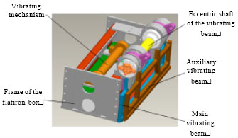
Paver screed mainly composed of the tamper mechanism (Zhao, 2009), the eccentric vibration mechanism and the ironing plane frame, among them, the tamper mechanism also includes the eccentric shaft, main vibrating beam, auxiliary vibrating beam, main eccentric sleeve and auxiliary eccentric sleeve, it is shown in Fig. 1.
The double-tamper mechanism is in the front of the flatiron-box, it could realize the initial compaction of the paving mixture by the movement of vibration beam driven by the rotation of eccentric shaft, its rotation frequency is generally 0-25 Hz.
 | |
| Fig. 1: | Schematic diagram of the structure of screed |
The inertial force produced in the rotation will have a greater influence on the flatiron-box. Eccentric vibrating mechanism is mainly used the eccentric shaft mounted on the screed rotary motion generated centrifugal force to drive the vibration of the screed, play the role of compaction and surface finishing when paving hybrid materials, the vibration frequency adjustable steplessly from 0-50 Hz.
DYNAMIC ANALYSIS MODEL OF SCREED
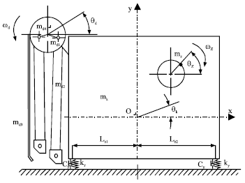
According to the structure and working process of the screed, the dynamic model is shown in Fig. 2. In the figure, mk is mass of the ironing plane frame, md1 is eccentric sleeve mass of main vibrating beam, md2 is basic section mass of the main vibrating beam, md3 is basic section mass of the auxiliary vibrating beam, md4 is eccentric sleeve mass of auxiliary vibrating beam, ωz is speed of vibration mechanism, ωd is speed of the tamper mechanism, Lb1 is the distance from screed frontier to screed centroid, Lb2 is the distance from the trailing edge of the screed to screed centroid. Under the action of the vibrating mechanism and the double-tamper mechanism, screed compact the pavement.
Mechanical model of the double-tamper mechanism: The tamper eccentric shaft is fixed on the frame of the flatiron-box. The eccentric shaft is usually driven by hydraulic motor. Let the vibration beam move up and down in the vertical direction and compacts the paving materials. Tamper mechanism is a plate - beam structure, grid plate is on top of the beam and the beam is hung on the eccentric shaft (Xia, 2004). The double-tamper mechanism can be seen as four rigid bodies, namely, left and right eccentric sleeves, main and auxiliary vibrating beams. G1~G4 indicate each centroid of the four rigid body.
 | |
| Fig. 2: | Dynamic calculation model of screed |
By introducing set of Lagrange coordinates:
| (1) |
where, θd1, θd2, θd3 and θd4 are the rotation angle displacement of each member of the double-tamper mechanism. The geometric equations of each rigid body centroid can be built as follow:
| (2) |
Differentiating the Eq. 2, the centroid velocity equation can be expressed as:
| (3) |
Differentiating Eq. 3, the centroid acceleration equation can be expressed as:
| (4) |
Through position constraint relations, put the θd2, θd3 and θd4 expressed as the function of θd1 and get ψi and ψi by the location function and velocity equations, thus the centroid velocity and the acceleration of each rigid bodies can be obtained.
According to the kinematics parameters of the double-tamper mechanism, the dynamics analysis of the system can be done. Assuming the eccentric shaft rotated at constant velocity, it can be seen in Fig. 2, left and right eccentric sleeve, also rotated at constant velocity, so the components 1, 4 only produce inertia force; main and auxiliary vibrating beam, namely, the components 2, 3 move as a rigid body plane motion and generate the inertia force and moment of inertia in the rotational process. These forces will produce a total force F and a torque M in rotation center which is the total inertia force and the moment of inertia of the double-tamper mechanism which can be expressed as:
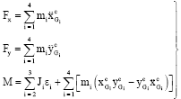 | (5) |
where, Jd2 is the moment of inertia of the main vibrating beam, Jd3 is the moment of inertia of the auxiliary vibrating beam, εd2 is the angle acceleration of the main vibrating beam, εd3 is the angle acceleration of the auxiliary vibrating beams.
Mechanical model of the eccentric vibrating mechanism: Eccentric vibrating mechanism is mainly used the eccentric shaft mounted on the screed rotary motion generated centrifugal force to drive the vibration of the screed, Its inertial force is calculated by the following equation:
| (6) |
where, mz is the quality of the eccentric portion of the vibration eccentric shaft, ez is the eccentricity of the vibration eccentric shaft.
Mechanical model of screed: From Fig. 2, the dynamic model of screed is a vibration system made of the vibration quality which includes the ironing plane frame, the tamper mechanism and the eccentric vibration mechanism, the elastic elements in the connection between the vibrating mass and foundation and the damping produced in the vibration process. According to working and dynamic principle, establishes the motion differential equations for the ironing plate:
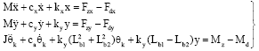 | (7) |
where, M is the mass of system, J is the moment of inertia of system, kx and cx is the stiffness and damping in x direction, ky and cy is the stiffness and damping in y direction, Fz is the exciting force of the vibration mechanism, Fd is the exciting force of the tamper mechanism.
The general solution of the Eq. 7 is attenuation to 0 in a very short time due to resistance, so only consider the solution of the forced vibration. In dynamic response calculation, the program has taken direct integration method and mode superposition method to calculate the transient and steady-state response of the structure. The two methods are used Wilson gradually integral method, the difference is that select different coordinates describing the movement, the former is solving equations of coupled structural dynamic in physical coordinates chosen by the finite element method, commonly used in the impact load excitation modes more and calculation time is shorter; while the latter is solving non-coupled equations after the transformation to the modal coordinates of solving the coupling equations, mainly used for the vibration mode by the load excitation force is less.
DYNAMICS ANALYSIS AND RESULTS
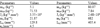
In this study, it has done the dynamics analysis of paver screed by taking a practical mechanism for example. The physical parameters of the screed are shown in Table 1.
Based on the dynamic theory model, the virtual prototype model of paver screed is established by the simulation software-ADAMS, the analysis of dynamic characteristic is carried out (Chen et al., 2012). According to system model, the software-ADAMS could automatically established Lagrange equation based on the dynamic theory of multi-body system and carry out the solution of kinematics and dynamics problems (Li, 2006). The 3D digital models and physical assembly relations are established by adopting the software Pro/E. Because the entity model is too complex, the model fillet, chamfer and some small quality components is to be deleted in order to simplify the model without affecting the results is to be deleted of simulation analysis (Luo et al., 2010).
The data transmission between Pro/E and ADAMS can be realized by using the specific interface module MECH/Pro. After defining rigid body and imposing constraints d in Pro/E, the model has been imported into the software-ADAMS thought the interface module MECH/Pro. Then Gravity constraints are applied to the entire mechanism, rotation constraints are added between the tamper and vibration eccentric shaft and joints of iron plate frame, rotation constraints are also added between the eccentric shaft and main and auxiliary vibrating beam. Bushing constraints are added between screed floor and the ground to simulate the flexible connection. Adding contact constraints between the panels and the main and auxiliary vibrating beam, the dynamic simulation model (Ren et al., 2010) of paver screed is shown in Fig. 3.
Dynamics analysis of double-tamper mechanism: The rotation of the double-tamper mechanism is driven by the hydraulic motor installed on the basic section mass of the flatiron-box.
| Table 1: | Structural parameters and quality attributes of paver screed |
 | |
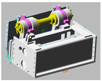 | |
| Fig. 3: | Dynamic simulation model of the paver screed |
 | |
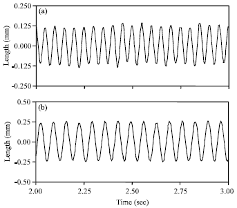
| Fig. 4(a-b): | Impact stroke of (a) Main vibrating beam and (b) Auxiliary vibrating beam |
The driving force is added on the rotation constrain of the connection of the eccentric shaft and the frame. Take the vibration frequency as 15 Hz and carry out the analysis of the model, then the impact stroke and centroid acceleration curve of the main and auxiliary vibrating beams are shown in Fig. 4 and 5.
As shown in Fig. 4, the impact stroke of the main vibrating beam is 4.987 mm, the impact stroke of the auxiliary vibrating beam is 6.019 mm which have a little difference compared with the design values that the main vibrating beam is 5 mm and the auxiliary vibrating beam is 6 mm, so they meet the analysis requirement.
 | |
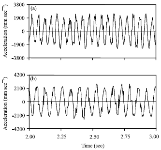
| Fig. 5: | Centroid acceleration curve of the main and auxiliary vibrating beams |
From Fig. 5, when the double-tamper mechanism moves, the phase difference of the centroid acceleration between the main vibrating beam and the auxiliary vibrating beam is 180° and the acceleration has a little difference, it indicates that the part of inertial force which is generated by the main and auxiliary vibrating beams can be offset.
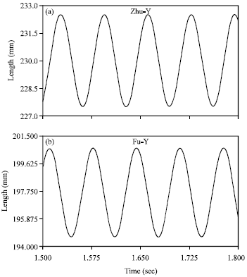
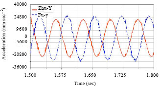
Dynamics analysis of screed when vibrating mechanism or tamper mechanism working alone: Drive over the vibration mechanism and the tamper mechanism, separately, take the vibration frequency as 20 Hz and the tamper frequency as 15 Hz to carry out the analysis of the model, then the displacement and acceleration curves of the screed mass are shown in Fig. 6 and 7.
As shown in Fig. 6 and 7, when the vibration mechanism work alone, vibration frequency of 20 Hz, the displacement peak of screed centroid is about 0.13 mm; the effective value of acceleration of screed centroid is 1.382 m sec-2. When the tamper mechanism work alone, tamper frequency of 15 Hz, the displacement peak of screed centroid is about 0.25 mm, impact on iron plate is larger than vibration system, amplitude increase nearly 2 times and the effective value of acceleration of screed centroid is 1.512 m sec-2.
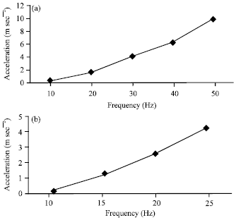
Under the condition of different vibration frequencies 10, 20, 30, 40 and 50 Hz to carry out the simulation of the system and take the effective value of acceleration to draw graphics. Then, do the system simulation at different tamper frequencies 10, 15, 20 and 25 Hz and also take the effective value of acceleration to draw graphics. The results are shown in Fig. 8.
 | |
| Fig. 6(a-b): | Displacement curve of screed centroid (a) When vibrating mechanism working alone and (b) When vibrating mechanism working alone |
 | |
| Fig. 7(a-b): | Acceleration curve of screed centroid (a) When vibrating mechanism working alone and (b) When vibrating mechanism working alone |
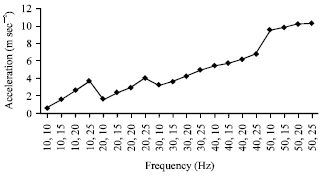
It can be seen in Fig. 8, the vibration acceleration RMS of screed increases with the increase of vibration and tamper frequency, among them, when the vibration frequency is 50 Hz, the vibration acceleration RMS of screed centroid reached 9.83 m sec-2, when the tamper frequency is 25 Hz, the vibration acceleration RMS of screed centroid reached 4.252 m sec-2.
Dynamics analysis of screed when tamper and vibrating mechanism working simultaneously: Drive over the tamper and vibrating mechanism simultaneously, take the tamper frequency as 15 Hz and the vibration frequency as 20 Hz and carry out the analysis of the model, then the displacement curve of the screed mass is shown in Fig. 9.
 | |
| Fig. 8(a-b): | Acceleration effective value of screed centroid (a) When vibrating mechanism working alone and (b) When vibrating mechanism working alone |
 | |
| Fig. 9: | Displacement curve of screed centroid when tamper and vibrating mechanism working simultaneously |
The acceleration and FFT curve of the screed mass is shown in Fig. 10.
It can be seen in Fig. 9, when the tamper and vibrating mechanism work simultaneously, the displacement peak of screed centroid is about 0.39 mm. As shown in Fig. 10, the vibration of screed is the combination of the two kinds of frequency, among them, the influence of the tamper mechanism to the ironing plate is larger than the vibration mechanism.
Under the condition of different tamper frequencies 10, 15, 20 and 25 Hz and different vibration frequencies 10, 20, 30, 40 and 50 Hz to carry out simulation of the system and take the screed centroid acceleration RMS to draw graphics at different frequency combinations, the results are shown in Fig. 11.
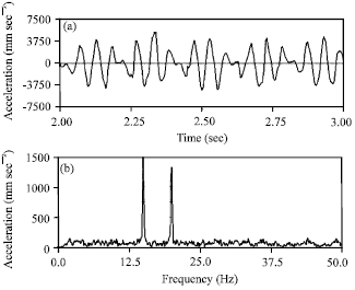 | |
| Fig. 10(a-b): | (a) Acceleration and (b) FFT curve of screed centroid when tamper and vibrating mechanism working simultaneously |
 | |
| Fig. 11: | Acceleration effective value of screed centroid when tamper and vibrating mechanism working simultaneously |
As shown in Fig. 11, when the vibration frequency in the low band, as the tamper frequency increases, screed board acceleration RMS increase faster while at high frequencies, the change of tamper frequency has less influence to the screed. Therefore it should be taken that a low vibration frequency in the precondition of meeting the pavement compaction density when the asphalt paver in the construction. The vibration mechanism has a small effect on the frame of flatiron-box at a low frequency.
CONCLUSION
In this study, theoretical analysis and dynamics model of paver screed have been carried out and the multi-body dynamic model is established based on the software Pro/E and ADAMS. The dynamics characteristic of the mechanism is also simulated. It is shown that with the increase in the frequency of vibration and tamper, screed vibration acceleration is increased by a big margin. The amplitude of screed caused by double-tamper mechanism is larger than the amplitude caused by vibration mechanism. When vibration frequency at the low band, the tamper mechanism has large influence to screed, so, it should be avoided that to use the combination of the low-frequency vibration and high-frequency vibrating.
Compared with previous simplified calculation model, the virtual prototype model is established according to the real machinery. It considers the space structure and mass distribution of each component, at the same time, it is convenient to adjust the model parameters to analyze experiment. A series of simulation results are obtained, through comparison and analysis, it can effectively guide the design, use and improvement of paver screed.
ACKNOWLEDGMENT
The research work is supported by A Project Funded by the Priority Academic Program Development of Jiangsu Higher Education Institutions.
REFERENCES
- Chen, Y.X., M.Y. Zang, Y. Chen and Z.H. Hu, 2012. Shift force analysis of manual transmission based on virtual prototyping technology. China Mech. Eng., 23: 996-1000.
Direct Link - Liu, G., P.Y. Tian, Z.Y. Xiao, L.Q. Xu and Y. Yu, 2005. Simulation of dynamic character of compacting mechanism of paver. Trans. Chin. Soc. Agric. Machinery, 36: 34-37.
Direct Link - Luo, T., X. Gan and W. Luo, 2010. Nonlinear dynamics simulation of compacting mechanism with double-eccentric vibrator of asphalt-paver. Proceedings of the International Conference on Intelligent Computation Technology and Automation, Volume 2, May 11-12, 2010, Changsha, pp: 800-803.
CrossRef - Ren, Y.P., Q.K. Han, T.X. Zhang and B.C. Wen, 2010. Dynamic simulation of forging manipulator based on virtual prototyping. J. Northeastern Univ. (Nat. Sci.), 31: 1170-1173.
Direct Link - Xu, Q., 2006. Kinematic analysis of tamper mechanism for paver. Road Machinery Constr. Mechanization, 23: 15-19.
Direct Link - Zhao, G.P., 2009. Analysis on dynamic characteristic of ironing mechanism of asphalt concrete paver. Road Machinery Constr. Mechanization, 6: 35-38.
Direct Link