INTRODUCTION
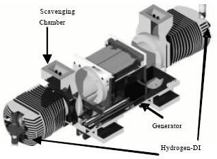
A linear generator engine (Fig. 1) is based on a free-piston
engine where it freely moves without any mechanical part relating to its motion.
It is a crank-less reciprocating engine, having no connections to any camshaft,
compressor or power-steering pump; thus, it has no mechanical output and experiences
less friction. Due to the absence of the crankshaft, its side load friction
from the piston is reduced. As a result, the LG has a high mechanical efficiency.
It's simple design contains fewer parts, is less costly, less maintenance is
required and is more reliable. Due to its small compact design, it has a high
power to weight ratio (Zulkifli, 2007; Zulkifli
et al., 2009). The objectives of this research are to integrate and
to test the new MOSFET inverter and gate driver to the current system and to
be able to motor the LG from 3 batteries up to 7 batteries and to perform combustion
while motoring with 3 and 5 batteries.
LINEAR GENERATOR
Working principle: The LGs basic operating principle is based
on a 2-stroke engine where exhaust and intake stroke is completed within 1 cycle
and the compression and power stroke is 1 cycle.
|
Fig. 1: |
UTP two-stroke hydrogen-DI linear generator free-piston engine
prototype |
The difference between 2-stroke and 4-stroke engine is that a 4-stroke engine
produces 1 power stroke in every 2 revolutions, while a 2-stroke engine produces
1 power stroke in each revolution.
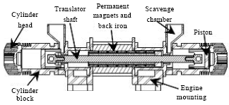
|
Fig. 2: |
LG cross-sectional view |
The LG is operated as a motor for starting of the LG. During motoring, air
will enter through the opening ports into the combustion chamber. Towards the
end of the compression process, hydrogen is injected directly into the combustion
chamber as a fuel to combust by the spark plug. The combustion energy will then
push the piston towards the other end and the process repeats itself. The back
and forth motion of the translator (which consists of a permanent magnet assembly
as shown in Fig. 2 will cut the magnetic fields to produce
electricity (Hanipah, 2008).
This output energy can then be used to charge batteries or directly power an
electric motor in a series configuration of a Hybrid Electric Vehicle (HEV).
As for lubrication, it uses the same concept as most 2-stroke engines: lubrication
is injected into the incoming air going into the cylinder in the form of fine
mist. Once it is in contact with the surface, the lubrication provides smooth
movement of mechanical parts such as the shaft and piston (Ibrahim
et al., 2011).
Technical review of hydrogen-fueled internal combustion engine: This
study discusses combustion characteristics, problems, future development and
optimization of a hydrogen internal combustion engine (H2ICE) to
achieve better performance and near zero emission. Due to the characteristics
of hydrogen, H2ICE is able to burn cleanly and work efficiently at
ultra-lean combustion and low engine load while reducing the production of NOx.
It is said that the main problem with using hydrogen is the pre-ignition (since
hydrogen has a low ignition energy) which is caused by engine hot spots, such
as spark electrodes, valves or engine deposits which can cause engine peak power
output to be reduced by 50% compared to engine operation with gasoline (White
et al., 2006).
Therefore, for practical application, the maximum Equivalence Ratio (ER) and
consequently, peak power output can be limited by the pre-ignition limit. This
problem can be minimized using cold-rated spark plugs, low coolant temperature,
optimized fuel-injection timing and advanced engine control strategies such
as intake charge cooling, variable valve timing for effective scavenging of
exhaust residuals, advanced ignition systems and hydrogen Direct Injection (DI)
(White et al., 2006).
The direct injection H2ICE has long been viewed as one of the most
attractive advanced H2ICE options since it produces higher volumetric
efficiency due to the ability to inject the fuel after the intake valve is closed.
This method also has a good potential to avoid pre-ignition. It is known that
the potential of DI-H2ICE power density to be approximately 115%
that of an identical engine operated on gasoline. The challenge with DI-H2ICE
is that in-cylinder injection requires hydrogen-air mixing in a very short time.
Experimental evidence demonstrates that complete mixing in an engine takes approximately
10 msec (White et al., 2006).
Another interesting fact is that if the H2ICE is used to drive an
alternator that generates electricity, it can be operated and optimized for
single-speed operation at maximum power (White et al.,
2006).
Performance characteristics of a hydrogen-fuelled free-piston internal combustion
engine and linear generator system: This study describes the performance
of a Free-piston Engine (FPE) with an engine capacity of 150.8 or 100.5 cc depending
on 2 types of fuel applications: either Compressed Natural Gas (CNG) or hydrogen.
When CNG fuel is used, the piston stroke is elongated for half of the original
stroke to draw more useful work out of the generator (Woo
et al., 2009). The engine speed is controlled mainly by adjusting
the ignition timing.
From experimental data shown in Woo et al. (2009),
the peak cylinder pressure with combustion using CNG as fuel is around 25-30
bar with piston frequency of 13 Hz and a few recorded misfires. With hydrogen
as fuel, the test engine was operated at 13 Hz with peak cylinder pressure of
30-35 bar. The increase in pressure when using hydrogen is due to the high combustion
speed of hydrogen. From the rate of heat release graph, the combustion duration
is longer for CNG compared to hydrogen. All the combustion heat released recorded
is before the pistons TDC. Ignition timing was adjusted to adjust the
position of the peak cylinder pressure to occur after TDC but due to instability
of the engine, it stops after several minutes of operation.
APPROACH AND METHODS
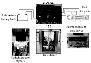
Experimental setup: A control and data acquisition (DAQ) system based
on National Instruments (NI) hardware and software is used to control the engine
and to log data during experimentation (Fig. 3).
|
Fig. 3: |
Experimental setup for linear generator |
Data logging is performed on a 10-kHz sampling frequency to attain accurate
results for data post-processing. For current injection and switching purposes,
signal from the control system is amplified by the gate driver to operate the
MOSFET inverter. The battery bank consists of 7 sets of 12 V automotive lead-acid
batteries connected in series, to provide electrical energy to the LG during
the motoring and starting process.
For the combustion experiments, hydrogen gas is used as the fuel. It is directly
injected into the combustion chamber and ignited by spark plugs. The injection
and ignition timing are all controlled by the NI control and DAQ system, running
LabVIEW 7.1 software.
RESULTS AND DISCUSSION
Previously, an inverter based on IGBT (insulated-gate bipolar transistors)
was used as the main driver for LG since it can handle far greater voltage and
current levels compared to a MOSFET inverter (Ibrahim et
al., 2011). Yet, due to its complexity of operation and based on previous
experimental results which were not very encouraging, it was then agreed to
perform further testing using MOSFETs but with an upgraded gate driver. New
MOSFET transistors from International Rectifier (part No. IRFB4110PBF) are selected
to be able to handle up to 100 Volts and 160 Amps (total of 8 batteries) of
operation. Also, a new gate driver is used to operate it.
Using the new MOSFET transistors: Motoring comparison between new and old
gate drivers: Installation of a new MOSFET gate driver takes place to replace
the old and problematic gate driver which had been causing unstable engine operations.
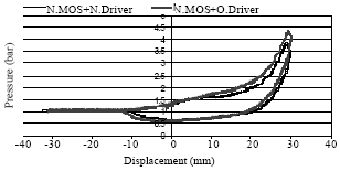
|
Fig. 4: |
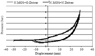
Pressure vs. displacement for motoring with 3 batteries |
|
Fig. 5: |
Pressure vs. displacement for motoring with 5 batteries |
Testing is performed to compare motoring results with the previous MOSFET gate
driver and to continue with further experiments. Figure 4
below compares between the new and old gate drivers in motoring tests with 3
batteries. The old driver produces a higher peak cylinder pressure of 4.2 bar
while the new gate driver produces only 3.87 bar.
The new gate driver has a lower pressure due to slightly lower battery power
(36 volts) while fully charged battery is at 38 volts. A 2-volt difference is
still acceptable to proceed with experiments but it will produce less compression
pressure. The important aspect is that both graphs show similar movement and
pressure patterns.
Figure 5 shows results of motoring with 5 batteries. As before,
the slightly less battery voltage with the new gate driver produces a lower
peak cylinder pressure of 5.5 bar, compared to 6.98 bar with the new gate driver.
Otherwise, the trend in both movement and pressure profiles is the same. These
results conclude that the new gate driver is stable and reliable for further
experimentation.
Motoring with the new MOSFET transistors and gate drivers: using 3, 5, 6
and 7 batteries: With the new MOSFET inverter and gate driver installed,
further experiments can be performed since it can handle higher voltage and
current of using more batteries.
|
Fig. 6: |
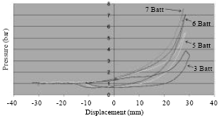
Pressure profiles of motoring from 3 to 7 batteries |
Table 1: |
Experimental results of motoring from 3 to 7 batteries |
 |
Motoring is carried out using 3, 5, 6 and 7 batteries which correspond to 36,
60, 72 and 80 V, respectively. From Fig. 6, it can be seen
that with higher motoring voltage, peak pressure will increase and the pressure
profiles become steeper (move closer towards the y-axis). Thus, motoring with
7 batteries achieves higher compression pressure faster and at shorter stroke
compared to 3, 5 and 6 batteries. The comparison of pressure and velocity is
shown in Table 1.
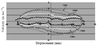
Previously it can be seen (Fig. 7) that motoring with 7 batteries
produces a higher compression pressure on a shorter stroke. This is because
with higher voltage, piston speed is higher, resulting in less air leakage through
the piston rings, thus producing higher compression pressure. Having higher
compression pressure will produce a denser air charge for combustion. To compare
the velocities, 7-battery motoring has the highest piston speed of 2 m sec-1,
followed by 6 batteries (1.5 m sec-1), 5 batteries (1.1 m sec-1)
and 3 batteries (0.5 m sec-1).
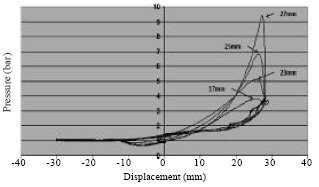
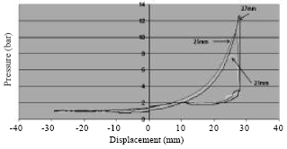
Motoring with 3 batteries, with combustion: Many combustion cycles have
been experimented using 3 batteries and the highest combustion pressure that
could be obtained was 9.4 bar with the following settings: injection at 27 mm,
1.6 Equivalence Ratio (ER), ignition at 28.125 mm and TDC at 28.125 mm. Injection
points are varied from 17 to 27 mm and the resultant PV diagrams are shown in
Fig. 8.
Moving the injection point closer to TDC results in higher combustion pressure.
Injection at 17 mm is a little too early and due to the slow piston speed in
motoring with 3 batteries, considerable charge leaks through the piston rings
causing low combustion pressure. Since injection points nearer to TDC will produce
higher pressure, further attempt to experiment with 17 mm injection is halted.
|
Fig. 7: |
Velocity profiles of motoring from 3 to 7 batteries |
|
Fig. 8: |
Pressure vs. displacement with constant fuel ER of 1.6 |
|
Fig. 9: |
IMEP vs. injection point with varied fuel ER of 0.3, 1 and
1.6 |
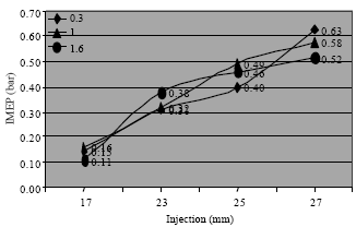
In Fig. 9 IMEP is determined and plotted for different values
of ER, while the injection point is varied, to show overall engine performance.
It can be seen that the relation of IMEP to injection point approximates a linear
trend. Late injection at 27 mm produces better IMEP. The highest IMEP is produced
by 27 mm injection with 0.3 ER which is at 0.63 bar. The reason a higher ER
produces slightly lower IMEP at 27 mm injection will be discussed in the following
section.
Motoring with 5 batteries, with combustion (varying injection point and
equivalence ratio): Injection point is selected at several points: early
injection (23 mm), middle injection (25 mm) and late injection (27 mm).
|
Fig. 10: |
Pressure vs. displacement for constant injection point of
23 mm |
For each constant injection point, hydrogen fuel is varied with Equivalence
Ratio (ER) of 0.3 to 5. LG is motored using 5 batteries, with the Top Dead Center
(TDC) at 28 mm and ignition point at 27.625 mm.
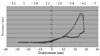
Varying fuel ER with fixed injection point of 23 mm: Figure
10 shows the PV diagram for motoring runs with a fixed 23 mm injection point
and varied fuel ER. In terms of trend, the overall fuel range produces the same
combustion behaviour but at 1 and 1.6 equivalence ratio, higher combustion pressure
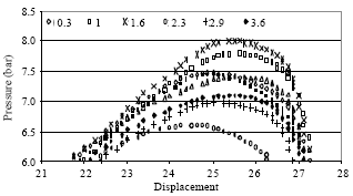
is produced (7.8 and 8 bar, respectively). Figure 11 shows
a close-up view of the peaks of the pressure curves, for a clearer comparison.
The highest pressure recorded in Fig. 11 is 8 bar with an
ER of 1.6 while the lowest is 6.6 bar at 2.3 ER. It is noticed that there is
not much pressure difference between ER of 2.9 to 5 (pressure range is 7 to
7.4 bar). This indicates better combustion pressure at ER stoichiometric of
1 and slightly rich ER of 1.6.
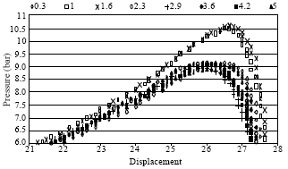
Varying fuel ER with fixed injection point of 25 mm: Figure
12 shows a close-up of the PV diagrams of motoring with an injection point
of 25 mm. The highest pressure values recorded are 10.6 and 10.5 bar for fuel
ER of 1.6 and 1, respectively. The rest of ER only produces combustion pressure
in the range of 8.9 to 9.1 bar. Combustion pressure produced by injecting fuel
at 25 mm seems to perform better compared to 23 mm.
Varying fuel ER with fixed injection point of 27 mm: Injection point
at 27 mm is very near to the ignition point of 27.625 mm. Results are shown
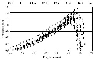
in Fig. 13. Comparing the 3 injection points (23, 25 and
27 mm), the highest combustion pressure recorded is 12.7 bar at 27 mm injection
with 1 ER, followed by 1.6 ER (12 bar) and 0.3 ER (11.78 bar).
|
Fig. 11: |
Pressure vs. displacement for constant injection point of
23 mm (close-up) |
|
Fig. 12: |
Pressure vs. displacement for constant injection point of
25 mm (close-up) |
|
Fig. 13: |
Pressure vs. displacement for constant injection point of
27 mm (close-up) |
It seems that high combustion pressure is frequently produced at near stoichiometric
point which is at 1 ER and slightly rich mixture at 1.6 ER. This is also true
in previous studies (Hanipah, 2008). Fuel with higher
than 1.6 ER would lower the chance of complete combustion due to lack of air
as reactant in the cylinder.
Varying injection point with constant fuel ER: To clearly show the effect
of varying the injection point, a constant fuel of 1 ER is chosen since it produces
the highest combustion pressure across the range of injection points experimented
previously: 12.7 bar. A comparison graph is plotted in Fig. 14.
|
Fig. 14: |
Pressure vs. displacement for constant fuel of 1 ER |
|
Fig. 15: |
IMEP vs. injection point with fuel ER of 0.3, 1, 1.6 and 5 |
It can be clearly seen that when fuel injection is near to the ignition point
and TDC, higher overall combustion pressure are produced throughout the ER range.
This is because late injection improves volumetric efficiency, resulting in
higher compression pressures (denser charge) prior to ignition (Hanipah,
2008).
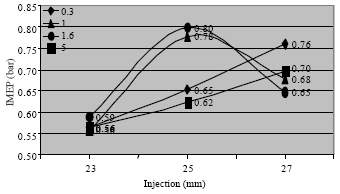
Indicated mean effective pressure (IMEP): IMEP is a useful relative
measurement of engine performance; hence, Fig. 15 is plotted
for fuel ER of 0.3, 1, 1.6 and 5-chosen to compare overall engine performance
since it varies from lean to rich. Highest IMEP obtained is 0.8 bar produced
by 1.6 ER at 25 mm injection, followed by 0.78 bar (1 ER, 25 mm injection) and
0.76 bar (0.3 ER, 27 mm injection). The reason highest IMEP is produced with
25 mm injection point is because the charge has sufficient time to mix fuel
and air before combusting at the 27.625 mm ignition point. The duration of time
between injection event (25 mm) and ignition event (27.625 mm) is 12.7 msec,
allowing for a complete air-fuel mixing (White et al.,
2006).
CONCLUSION
It can be concluded that late injection will produce higher combustion pressure
but due to insufficient time for air-fuel mixing, IMEP would be affected. Lower
battery capacity (3 batteries) produces lower combustion pressure due to the
lower compression pressure, thus failing to deliver denser air charge at the
point before ignition. The most effective range of combustion occurs with a
fuel ER of 1 and 1.6. Hence, combustion with 1.6 ER at 25 mm injection-producing
an IMEP of 0.8 bar-is favorable. Motoring with 5 batteries, using the new MOSFET
transistors and new gate driver, looks very promising for starting and combustion
of the LG. Further experimentation of the LG will be focused on combustion with
higher battery capacity to produce higher combustion pressure and higher IMEP
to achieve stable idling.