
D. Mehta Prarthan
Department of Electronics and Communication Engg., Faculty of Technology, Dharmsinh Desai University, Nadiad, India
S. B. Chakrabarty
Space Applications Centre, Ahmedabad, India
Journal of Applied Sciences
Year: 2011 | Volume: 11 | Issue: 12 | Page No.: 2250-2254


ABSTRACT
The capacitance of metallic tilted plates forming a corner is analyzed using Method of Moments based on pulse basis functions and point matching. The charge distributions on the conductor surfaces and capacitance of metallic tilted plate are found by solving the integral equation relating the potential on the conductor surface and unknown charge distribution by applying Method of Moments. Numerical data on capacitance and charge distribution are presented. The validity of the analysis was carried out by considering the tilt angle as 180° which is a case of rectangular plate and for which the data on capacitance is available in the literature.
PDF Abstract XML References Citation
Received: October 01, 2010;
Accepted: February 07, 2011;
Published: May 02, 2011
How to cite this article
D. Mehta Prarthan and S. B. Chakrabarty, 2011. Capacitance of Metallic Plates Forming a Corner. Journal of Applied Sciences, 11: 2250-2254.
DOI: 10.3923/jas.2011.2250.2254
URL: https://scialert.net/abstract/?doi=jas.2011.2250.2254
DOI: 10.3923/jas.2011.2250.2254
URL: https://scialert.net/abstract/?doi=jas.2011.2250.2254
INTRODUCTION
The spacecraft bodies in orbits experience significant charge buildup on its’ surfaces during inconsistent magnetic storm periods caused by the emission of charged particles from the sun. Rapid change in the accumulated charge distribution on satellite bodies produces current pulse, the consequence of which is the generation of electromagnetic pulse causing electromagnetic interference (EMI). This type of EMI may be very damaging to spacecraft electronic sub-systems. In order to study the phenomenon of EMI in space-craft bodies, the estimation of equivalent circuit parameters of exposed bodies of space-craft of different geometrical shapes is imperative. Capacitance is a very important circuit parameter needed for the analysis of Electrostatic Discharge (ESD) which causes EMI. Electrostatic modeling for the evaluation of capacitance and charge distribution of finite metallic bodies of different geometrical shapes like rectangular plate, cylinder, truncated cone, paraboloid, hemisphere, cube etc., which are widely used in orbiting spacecraft are presented by Ouda (2010), Wei et al. (2010), Azimi and Golnabi (2009), Ghosh and Chakrabarty (2008), Hwang and Michael (2004), Bai and Lonngren (2002, 2003, 2004), Das and Chakrabarty (1997a, 1998), Adams (1972) and Harrington (1968). In space-craft bodies, a number of sharp corners are present. Thus the evaluation of capacitance and charge distribution of corner formed by two rectangular metallic plates is of interest. The analysis of two metallic plates forming an arbitrary angle corner is not available in the open literature to the best of authors’ knowledge.
In this study, the evaluation of capacitance and charge distribution of metallic structure in the form of two plates forming a corner is presented using Method of Moment (MoM). In the present case, a set of two integral equations is formed by relating the unknown charge distribution on the two metallic plates forming the corner to the known potential on the corresponding metallic surface. In order to solve the integral equations by MoM, the surfaces of conductors are divided into rectangular subsections. The unknown charge densities are expanded using pulse basis functions and delta functions are used as testing functions for generating the set of simultaneous equations (Ouda, 2010; Wei et al., 2010; Azimi and Golnabi, 2009; Ghosh and Chakrabarty, 2008; Adams, 1972). The unknown charge densities are found from the inversion of the matrix formed from the set of simultaneous equations. The numerical data of the capacitances as well as charge distributions on the surface of the metallic plates are presented.
ANALYSIS
Two metallic rectangular plates of size 2ax2b and 2ax2c, forming a corner of angle θ, with the co-ordinate system is shown in Fig. 1.
For the plate 1 which is oriented in the X-Y plane with Z-axis perpendicular to the surface; the origin of the co-ordinate system is located at the geometrical centre point of plate 1.
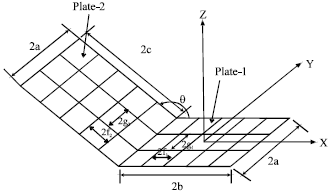 | |
| Fig. 1: | A metallic plates forming arbitrary angle θ |
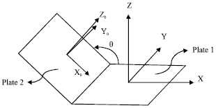 | |
| Fig. 2: | Co-ordinate systems for plate 1 and 2 |
For the plate 2, a local co-ordinate system X0-Y0-Z0 may be defined by rotating the X-Y-Z coordinate system by an angle θ with respect to Y-axis and translating this rotated co-ordinate system to the centre of plate 2. The schematic of the local co-ordinate system X0-Y0- Z0 for plate 2 is shown in Fig. 2. The coordinates of each point on plate 2 can be written in terms global co-ordinate system (x,y,z) by using coordinate transformation formula.
The formula for the transformed co-ordinate system is given as under:
 | (1) |
The potential at any point of position vector r due to charge on the conductor surfaces are of the form, (Wei et al., 2010; Azimi and Golnabi, 2009; Ghosh and Chakrabarty, 2008; Das and Chakrabarty, 1997b):
| (2) |
where, s1 and s2 represent metallic surfaces ![]() and
and ![]() represent position vectors for points on plate 1 and 2, respectively.
represent position vectors for points on plate 1 and 2, respectively.
In order to find the capacitance of the structure shown in Fig. 1, the knowledge of unknown charge distribution on the metallic surfaces should be known. Assuming the value of potential on both the metallic surfaces as V1 and V2, the following integral equations can be obtained from Eq. 2:
| (3) |
| (4) |
The capacitance and unknown charge distribution on the metallic surfaces of the structure shown in Fig. 1 may be found by solving the integral Eq. 3 and 4 by method of moments. In order to apply the method of moments, the surfaces of metallic plates 1, 2 are divided into M1xN1 and M2xN2 equal sub areas of the size 2g1x2f1, and 2g2x2f2, respectively.
The unknown charge distributions appearing in the integral equations are expressed in terms of known basis function (Azimi and Golnabi, 2009; Ghosh and Chakrabarty, 2008; Adams, 1972) as:
| (5) |
where, fn are the pulse basis functions given by:
In order to simplify the analytical complexity, it is assumed that the charge on each rectangular sub-section is concentrated at its center (Ghosh and Chakrabarty, 2008; Harrington, 1968). Substituting Eq. 5 in Eq. 3 and 4 and matching the boundary conditions for the potential at the center point of each subsection and following the procedure of Ghosh and Chakrabarty (2008) and Das and Chakrabarty (1997c), the equations reduce to the form:
| (6) |
| (7) |
The set of simultaneous equations, resulting from Eq. 6 and 7 lead to matrix equation of the form:
| (8) |
In Eq. 8 the non-diagonal elements of 111 and 1 22 can be written as (Adams, 1972):
| (9) |
| (10) |
The expressions for the elements of 112mn and 121mn are as follows:
| (11) |
| (12) |
The diagonal elements of 111 and 122 can be written following the procedure suggested in (Adams, 1972):
| (13) |
| (14) |
Using the method for the inversion of a matrix by partitioning it into sub-matrices, the solution of Eq. 8 is obtained as:
| (15) |
where, [ξmn] are the sub-matrices of the inverted co-efficient matrix as given by Eq. 8.
The charge distributions on the metallic as well as dielectric faces are obtained from the unknown coefficients of α’s obtained by solving the above matrix Eq.
The total charge on the surface of plate-1 is:
| (16) |
Similarly, the charge on the surface of plate-2 is:
| (17) |
The total charge on the conductor is:
| (18) |
The capacitance of the structure shown in Fig. 1 assuming V1 = V2 = V is:
| (19) |
RESULTS AND DISCUSSION
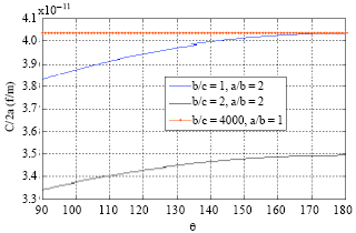
Using the Eq. 9 through Eq. 19, the capacitance per unit length of the metallic tilted plates for the geometry shown in Fig. 1 is evaluated with a/b, a/c and θ as parameters. The convergence of the numerical data on the capacitance per unit length is checked for each parameter. The convergence data is presented in Fig. 3. The variation of normalized capacitance as a function θ, with a/b and a/c as parameters has been computed and is shown in Fig. 4. Figure 5 shows the normalized capacitance per unit length for the metallic tilted plates, for different values of a/c. The charge distribution along the XY plane for the surface of plate-1 and the charge distribution along the X0Y0 plane for the surface of plate-2 are shown in Fig. 6 and 7, respectively for parameters a/b=a/c = 2 and θ = 135°. Table 1 shows the comparison of the data for the capacitance of a square plate presented by Harrington (1968) with that of the present configuration for θ = 180°, a/b = a/c = 2 which is the case of a square metallic plate.
The data of capacitance and charge distribution for the geometry shown in Fig.1 are not available in open literature and hence the validation of the results of analysis has been done for a special case of the geometry of Fig. 1 in which the angle between the two plates is 180°.
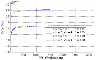 | |
| Fig. 3: | Convergence of the Capacitance C/2a (f/m), with a/b, a/c and θ as parameters |
 | |
| Fig. 4: | The capacitance per unit length as a function of θ, with a/b and a/c as parameters |
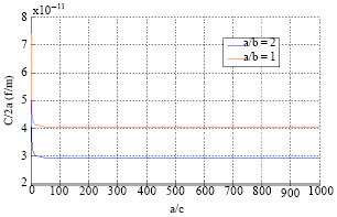 | |
| Fig. 5: | The capacitance per unit length as a function of a/c, with a/b as parameters for θ = 135° |
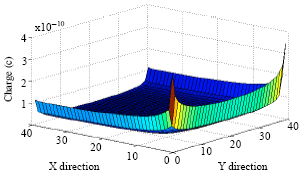 | |
| Fig. 6: | Charge distribution on the surface of plate-1 along the XY-plane |
The geometry of Fig. 1 turns into a flat metallic plate when the angle between the two plates is 180° and the capacitance of a flat rectangular plate has been reported by Ghosh and Chakrabarty (2008), Das and Chakrabarty (1998)and Harrington (1968).
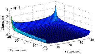 | |
| Fig. 7: | Charge distribution on the surface of plate-2 along the X0Y0-plane |
| Table 1: | Comparison of the method presented by Harrington (1968) and the present method |
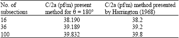 | |
The numerical data for the parameters, θ = 180°, a/b = a/c = 2, were compared with the results obtained for the square metallic plate presented by Harrington (1968). The close agreement between the data on capacitance as seen from Table 1 justifies the validity of the analysis. The validity of data was also checked by comparing the data on capacitance available in Ghosh and Chakrabarty (2008) with that computed by the present method. The data on capacitance/length (C/2a) computed by the present method for a/b = a/c = 2, θ = 180° and N = 32 is 39 pF/m which closely matches with the C/2L = 38.69 pF/m in Ghosh and Chakrabarty (2008) for the same parameters (L/W = 1 and N = 32). The capacitance data of a rectangular plate coated with dielectric was reported by Das and Chakrabarty (1998). They presented data on capacitance for very low thickness of dielectric coating. The value of the capacitance for very low value of dielectric constant should be comparable to the value of capacitance without dielectric coating. The value of capacitance presented by Das and Chakrabarty (1998) for a square plate of dielectric thickness/length = 0.001 is 39.53 pF closely matches with that given in Table 1. This also justifies the validity of the analysis. Convergence plot for the capacitance of the structure per unit length is shown in Fig. 3. Figure 5 re-authenticate the method used in this study by showing the convergence of capacitance for very large value of a/c ratio of the structure shown in Fig. 1, to an equivalent capacitance of unit square plate. It is apparent from Fig. 6 and 7 that the peak of charge distributions along the surfaces connected to the surfaces of another metallic plate is lower because the two plates are connected.
REFERENCES
- Ouda, M., 2010. Efficient capacitance matrix computation of large conducting bodies using the characteristic basis function method. J. Applied Sci., 10: 1622-1626.
CrossRefDirect Link - Wei, J., L. Oi, S. Liu, X. Cui and W. Zhang, 2010. Capacitance parameter extraction of HVDC converter system by the method of moments. Proceedings of the 14th Biennial IEEE Conference on Electromagnetic Field Computation, May 9-12, Chicago, pp: 1-1.
CrossRef - Azimi, P. and H. Golnabi, 2009. Precise formulation of electrical capacitance for a cylindrical capacitive sensor. J. Applied Sci., 9: 1556-1561.
CrossRefDirect Link - Ghosh, S. and A. Chakrabarty, 2008. Estimation of capacitance of different conducting bodies by the method of rectangular subareas. J. Electrostat., 66: 142-146.
Direct Link - Hwang, C.O. and M. Michael, 2004. Electrical capacitance of unit cube. J. Applied Phys., 95: 3798-3802.
CrossRef - Bai, E.W. and K.E. Lonngren, 2004. Capacitors and the method of moment. Comput. Electr. Eng., 30: 223-229.
CrossRef - Bai, E.W. and K.E. Lonngren, 2003. The spherical capacitor: A vehicle to introduce numerical methods. Comput. Electr. Eng., 29: 231-234.
CrossRef - Bai, E.W. and K.E. Lonngren, 2002. On the capacitance of a cube. Comput. Electr. Eng., 28: 317-321.
CrossRef - Das, B.N. and S.B. Chakrabarty, 1998. Rigorous analysis of the effect of dielectric coating on metallic bodies isolated in free space. Proc. INSA-A, 64: 137-148.
Direct Link - Das, B.N. and S.B. Chakrabarty, 1997. Capacitance and charge distribution of two cylindrical conductors of finite length. IEE Proc. Measurement Technol., 144: 280-286.
CrossRef - Das, B.N. and B. Chakrabarty, 1997. Calculation of the electrical capacitance of a truncated cone. IEEE Trans. Electromagnetic Compatibility, 39: 371-374.
CrossRef - Das, B.N. and S.B. Chakrabarty, 1997. Capacitance of metallic structures in the form of paraboloidal and spherical reflectors. IEEE Trans. Electromagn. Compat., 39: 390-393.
CrossRef