
Nordin Yahaya
Reliability Engineering and Safety Assessment Research Group (RESA), Department of Structure and Material, Faculty of Civil Engineering, Universiti Teknologi Malaysia
Norhazilan Md Noor
Reliability Engineering and Safety Assessment Research Group (RESA), Department of Structure and Material, Faculty of Civil Engineering, Universiti Teknologi Malaysia
Siti Rabe`ah Othman
Reliability Engineering and Safety Assessment Research Group (RESA), Department of Structure and Material, Faculty of Civil Engineering, Universiti Teknologi Malaysia
Lim Kar Sing
Reliability Engineering and Safety Assessment Research Group (RESA), Department of Structure and Material, Faculty of Civil Engineering, Universiti Teknologi Malaysia
Mazura Mat Din
Faculy of Computer Science and Information Technology, Universiti of Teknologi Malaysia, 81310, Skudai, Johor, Malaysia
Journal of Applied Sciences
Year: 2011 | Volume: 11 | Issue: 9 | Page No.: 1510-1518


ABSTRACT
Pipeline integrity management programs address a wide range of threats to safe operations. Among these threats, external corrosion has been among the most dominant failure mechanism experienced by buried steel pipelines. External corrosion can be detected through a variety of assessment methods, including inline inspection (ILI) and External Corrosion Direct Assessment (ECDA). In the absence of data from inspection, the corrosion rate can be estimated based on the use of buried corrosion coupons, corrosion probes and corrosion rate modelling using data derived from soil analysis. The objective of the study was to design a methodology of the external growth modelling of corrosion on buried gas pipelines under various exposures to soil conditions. The technique can be used to generate field data so as to model empirically the corrosion dynamic in soil or for verification of corrosion data from laboratory testing. The potential model based on the proposed technique is highly potential to predict the likelihood of corrosion growth rate experienced by buried lines exposed to corrosive environment. Hence, can greatly assist operator to secure the integrity of their pipelines until the structure reaches its designed lifetime.
PDF Abstract XML References Citation
Received: October 22, 2010;
Accepted: November 01, 2010;
Published: April 18, 2011
How to cite this article
Nordin Yahaya, Norhazilan Md Noor, Siti Rabe`ah Othman, Lim Kar Sing and Mazura Mat Din, 2011. New Technique for Studying Soil-Corrosion of Underground Pipeline. Journal of Applied Sciences, 11: 1510-1518.
DOI: 10.3923/jas.2011.1510.1518
URL: https://scialert.net/abstract/?doi=jas.2011.1510.1518
DOI: 10.3923/jas.2011.1510.1518
URL: https://scialert.net/abstract/?doi=jas.2011.1510.1518
INTRODUCTION
Corrosion is a common form of structure degradation that reduces both the static and cyclic strength of a pipeline. There is always the chance that pipelines could leak or rupture and a pipeline failure can cause serious human, environmental and financial losses (Hopkins, 1995; National Energy Board, 1996). As reported by Riemer (2000), the transportation of petroleum products and natural gas has begun since early of 20th century by using buried steel pipelines over long distance. There are over 1.28 million miles of buried steel main-line pipe for the transport of natural gas alone (American Gas Association, 1999).
It is the safest method to burry onshore and offshore transportation pipelines under soil for mechanical protection and to provide thermal insulation. Researchers have classified failure mechanisms associated with pipelines failures into three categories which are third-party damage, material defects and corrosion (Alodan and Abdulaleem, 2007; Ahammed and Melchers, 1997; Cheuk et al., 2007). Corrosion is recognised as one of the most dominant forms of deterioration process and has been identified as one of the major causes of loss containment for offshore steel pipelines (Ahammed, 1998).
Corrosion failures represent a significant proportion of the total number of failures of natural gas pipelines. Early detection of pipe thinning owing to corrosion in real time before failure occurs will enhance transmission pipeline reliability (Bullard et al., 2005). For that reason, mechanical devices and probes have been introduced to the industry so as to continuously monitor the internal and external condition of the lines under corrosion.
Even though periodic inspection has been regularly conducted to inspect pipeline condition both internally and externally, pipeline failure due to corrosion attack is still a major problem. Projecting the future growth of defects in order to determine the time to failure of the operational pipelines is not a straightforward task. This is due to inherent uncertainties associated with soil properties, material properties and imperfect measurement by the inspection tool. The operators are intensifying the need for a reliable empirical model especially for external condition. A pipe line damaged by external corrosion has been shown in Fig. 1.
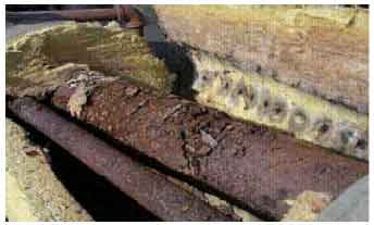 | |
| Fig. 1: | Pipeline damaged by external corrosion |
Research issues: Pipeline corrosion is most prevalent when the breakdown of coatings, inhibitors, or cathodic protection takes place in a corrosive environment. When it comes to pipeline integrity and corrosion, the two most important questions to a pipeline operator are how severe the corrosion is, and how quickly the integrity of the pipeline is deteriorating. The problems are that these factors do not affect the pipeline equally at all locations and corrosion does not grow at the same rate throughout a pipeline. If operator can identify those corrosion defects which are active or growing, then predictions of future corrosion severity for each and every defect can be made.
The existing corrosion mitigation programs are quite effective to combat corrosion problem. The difficulty is that for various reasons, programs can fail to provide adequate protection in specific, isolated areas. The reasons may include soil conditions, cathodic protection shielding and interference, or inadequate inhibitor concentrations. Any integrity management plan which addresses when to conduct future repairs and when to re-inspect the pipeline has a tendency to make some assumption of corrosion rate, whether explicitly or implicitly, due to insufficient information pertaining to metal loss mechanism. An estimation of corrosion rates may be applied from engineering judgement based on years of experience and intricate knowledge of a pipeline, or it may be a sophisticated scientific assessment incorporating detailed pipeline data (Nesic, 2007). A proper and accurate corrosion model can greatly assist engineers in making decisions related to design, operations and control.
Available model: Melchers and Jeffrey (2008) reported that models for corrosion loss are generally commenced with Tammann in 1923 who solved the mathematics for the diffusion of oxygen through the tarnish layers formed on copper, then followed by Booth (1971) who then refined the mathematics although this usually is simplified to a corrosion or pit depth c(t) growth law of the form as follows:
| (1) |
where, t is time and A and B are constants.
 | |
| Fig. 2: | Corrosion loss-exposure time model showing each of the phases and the parameters used to define them. |
This model is used in at least one very refined model for pit initiation and early pit growth (Englehardt and MacDonald, 1998). It also forms the basis for much modelling of long term atmospheric corrosion loss. Melchers (1997) postulated that the corrosion process changes with time and could be presented by a number of sequential phases as shown in Fig. 2. Melchers and Jeffrey (2008) then calibrated the model using an extensive re-examination of literature data and field tests on the involvement of anaerobic bacterial activity of mild steel in marine environments.
As reported by Shi and Mahadevan (2000), a seven-stage conceptual model was identified by Goswami and Hoeppner (1995) from the onset of corrosion fatigue fracture. A three-stage probabilistic model was proposed by Harlow and Wei (1994) to predict the corrosion fatigue life as well as a probabilistic model for the growth of corrosion pit induced by constituent particles. The transition model for pitting to corrosion fatigue crack nucleation has been first proposed by Kondo (1989) and further discussed by Chen et al. (1996).
Generally, deterministic and probabilistic models of varying degrees of accuracy are available for various stages of the corrosion fatigue life. The model that incorporates all the seven stages of corrosion life is proposed by Shi and Mahadevan (2000) using a comprehensive probabilistic method. The seven stages consists of pit nucleation, pit growth, transition from pitting to fatigue crack nucleation, short crack growth, transition from short crack to long crack, long crack growth and fracture.
To date, empirical model for predicting the growth of external corrosion defects on buried pipelines is hardly available. Most of the established models such as the De Waard et al. (1991) equation are meant for internal growth which governed by the flown product properties and operational condition. Moreover, the intricacy of physical corrosion models may deter pipeline operator from using it in their maintenance program. There is an immense need for new empirical model capable of estimating the growth rate of external defects under influence of soil properties. For buried gas pipelines, the external corrosion is a great concern than the internal growth due to severe exposure to various condition of soil. The internal corrosion for buried gas pipelines is less critical because the pipelines are used to transport processed gas or cleaned gas with less impurity. The benefits of the research is to give better understanding on the actual behaviour of corroding steel under exposure to various soil types and conditions, knowing the most optimum potential for cathodic protection for specific site, reduce the uncertainties in the estimation of corrosion growth, assist the operators in decision making and reduce the overall operating cost.
External corrosion of buried pipelines: Corrosion may act on the pipelines either internally or externally or both. Furthermore, it may be uniform or nearly uniform in nature or localised in extent and severity (e.g., pitting or crevice corrosion) (Ahammed and Melchers, 1997). External corrosion is a major factor contributing to the deterioration of buried pipelines; it weakens the pipe wall, which increases the risk of failure (Ahammed and Melchers, 1997). External corrosion is a function of the interaction between the pipelines and the soil that surrounds it (Doyle et al., 2003; Osella et al., 1998). The external corrosion of gas transmission pipelines is usually controlled by the application of various polymetric coatings augmented with Cathodic Protection (CP) (Bullard et al., 2005). Most common pipeline corrosion protection is done by coating with special material that protects the surface from corrosive elements, such as the type of the soil, moisture, pH, temperature variations and other factors such as resistivity and the presence of sulphate reducing bacteria (Alodan and Abdulaleem, 2007; Bullard et al., 2005; Doyle et al., 2003; Rim-Rukeh and Awatefe, 2006).
The common types of corrosion that can occur in a buried pipeline are: (a) pitting corrosion owing to material in-homogeneities, (b) chloride or sulphate induced stress corrosion cracking, (c) corrosion by concentration cells in soil arising out of differences in oxygen concentration in the soil adjacent to the pipe at different regions, (d) microbiologically induced corrosion under anaerobic conditions by sulphate-reducing bacteria (SRB) and Acid-producing Bacteria (APB), (e) tuberculation because of the build up of corrosion products on the internal pipe surfaces and (f) stray current corrosion by earth return direct currents.
Research objective: The objective of the study was to design a new technique/methodology to measure the actual metal loss of buried steel coupon on site. The metal loss information can be utilised to model the external corrosion as experienced by buried gas pipelines exposed to various soil conditions (soil types, properties and contents) or to verify corrosion potential data gained through Electrochemical Impedance Spectroscopy (EIS), for instance. It is of importance to identify the relationship between various soil conditions and the severity of corrosion rate so that the modelling of corrosion dynamic can simulate the actual mechanism as accurate as possible. The pipeline materials will be exposed to various environmental conditions and continuously monitored to determine the corrosion growth rate on site. Apart from modelling, the measured corrosion growth rate can also be utilised in the probabilistic-based assessment of pipeline integrity. Then, the outcomes of the assessment can be used for determination of inspection intervals and other integrity monitoring programmes.
The study focuses on the relationship of soil condition and degree of exposure to the external growth of corrosion defects. The available inspection data and previous maintenance record will be used to determine the exact location for soil sampling based on the severity of corrosion attack. The investigated pipelines throughout the research are made of steel from various grades and sizes.
Soil corrosion factors: Soil has many different meanings depending on the field of study. To a geotechnical engineer, soil has much broader meaning and can include not only agronomic material, but also broken-up fragments of rock, volcanic ash, alluvium, Aeolian sand, glacial material, and any other residual or transported product of rock weathering (Day, 2001). Its physical and chemical characteristics are different from sea-bed sediment soil, salina soil and tideland soil. Soil is a complex material; a porous heterogeneous and discontinuous environment constituted by mineral or organic solid phase, water liquid phase and airs other gas phase (Rim-Rukeh and Awatefe, 2006) (Ferreira et al., 2007). According to Ferreira et al. (2007), the soil is defined as an electrolyte and this can be understood by means of electrochemical theory. The study of the soil as a corrosive environment is necessary due to the large number of buried pipelines, tank and other structures, as their deterioration can represent a real economical and environmental problem throughout the years. There are several parameters that can affect the corrosivity of a soil such as resistivity, pH, redox potential, moisture content, type of soil, chloride and others.
In agreement with the parameters cited above, Fitzgerald (1993) studied shows the corrosivity of the soil influenced by oxygen content, dissolved salts, pH, elements that form acids, concentration of chloride, sulphide and sulphate, resistivity, total acidity, redox potential and others, depending on specific application. The specific test for external corrosion due to soil corrosivity will be discussed in the next section.
MATERIALS AND METHODS
The research duration is designed for 36 months period divided into several stages as shown in Fig. 3. The project will commences with a 6 month of initial data collection, site visits and establishment of research method. This will be followed by another 6 months of soil sampling, experimental set-ups, preparation of testing materials and initial experiments. Upon completion of the activities in Stage 1, corrosion experimental studies and simulation of predicted corrosion growth rates will be carried out in Stage 2 and followed by Stage 3 for a period of twelve months each.
 | |
| Fig. 3: | Flowchart of field work procedure |
The sequences of research activities are planned as shown in Fig. 3. An overview of test conducted in this study is shown in Fig. 4. Laboratory test may be classified conveniently as follows:
| • | Soil properties test is to determine the type of soil, with respect of their parameters comprises moisture content, liquid limit, plastic limit, plasticity index, shrinkage limit and particle size distribution |
| • | Soil corrosivity test is conducted to determine the effect of soil towards buried gas pipelines in study area. The parameter considered such as pH, temperature, resistivity, redox potential and chloride |
| • | Weight loss measurement test is performed to determine the corrosion growth of mild steel coupons that immersed in aqueous solution of the soil samples |
| • | Electrochemical Impedance Spectroscopy (EIS) is use to assess the corrosion behaviour of metals and alloys in service (Bullard et al., 2003). The most commonly used measurements are as follows: |
| • | Determination of the steady state corrosion potential Ecorr |
| • | Determination of the variation of Ecorr with time |
| • | Determination of the E-i relationship during polarisation at constant current density (galvanostic) the potential being the variable |
| • | Determination of the E-i relationship during polarisation at constant potential (potentiostatic) the current being the variable |
Laboratory studies have shown that electrochemistry-based corrosion rate probes can be used to monitor the corrosion of steel in soils (Shreir, 1976). Corrosion rates were shown to have a good agreement with gravimetric weight loss measurements and were also sensitive to changes in soil moisture and salt content. Others have shown that electrical resistivity probes can be used to monitor the effectiveness of cathodic protection of pipelines (Bullard et al., 2004; Khan, 2002). According to previous researchers there are several types of instrument, parameters and methods can be used in corrosion testing.
Laboratory-based corrosion tests fall into the following categories comprises immersion test, simulated atmosphere tests, electrochemical tests and environmentally aggressive tests (Fig. 4). All of these are accelerated tests by design and therefore must be carefully carried out.
Soil sample collection: Soil sample for this study will be randomly collected from different sites. At each of the selected site, samples will be collected by digging a hole of 1 m deep.
 | |
| Fig. 4: | Various test used to investigate corrosion mechanism on buried gas pipelines |
Soil samples will be collected from each sites and kept in polyethylene bags before sent to the laboratory immediately for further soil analysis.
Soil classification test: The major classification in identifying the type of soil is the grain size distribution test as determined according to ASTM D422-98 (American Standard of Material and Testing, 2007) and BS 1377-2:1990 (BSI, 1990a). Both wet sieving and sedimentation analysis are used to get full particle distribution analysis of the sample under investigation. The parameters analysed comprises moisture content, liquid limit, plastic limit, plasticity index, shrinkage limit and particle size distribution.
Soil corrosivity test: Adopting the BS 1377-3 (BSI, 1990b) and AWWA C105 standards (ANSI/AWWA C105/A21.5-99, 2000) for soil corrosivity testing, the following parameters are analysed based on the collected soil samples which are pH, temperature, soil type, moisture content, resistivity, redox potential and chloride (Cl–). Soil type is evaluated using the following characteristics such as the ability of water to penetrate soil, the ease with which soil was washed off the equipment and the consistency of the soil when manipulated in one’s hand.
Moisture content of the soil samples can be ascertained using the weight loss technique according to BS 1377-2:1990 (BSI, 1990a). An amount of 30 g of each sample is dried in a drying oven at 105°C for 24 h. The weight difference between the sample before and after evaporation is regarded as the moisture content. The pH and temperature are normally determined in-situ using a multi-parameter quality monitor according to ASTM G51-95 (American Standard of Material and Testing, 2005). Resistivity of the soil samples is measured using the Wenner Four-Electrode Method adopted in ASTM G57-06 (American Standard of Material and Testing, 2000b). The soil samples are saturated with distilled water and placed in different rectangular boxes with an open top. The boxes are filled to the top with soil. The value of resistivity can be evaluated using Eq. 2.
| (2) |
Where:
| R | = | Resistance (Ω) |
| A | = | Cross sectional area of the container perpendicular to the current flow (cm2 ) |
| a | = | Inner electrode spacing (cm) |
| ρ | = | Resistivity (Ω.cm) |
Temperature is an important parameter in the investigation of soil corrosivity because it can modify the interactions between the metal and the soil conditions (Rim-Rukeh and Awatefe, 2006). Soil resistivity is a measure of the ability of a soil to conduct an electrical current (Rim-Rukeh and Awatefe, 2006) (American Standard of Material and Testing, 2000b). The resistivity of the soil is determined by moisture content and the concentrations of the different ions and their mobility. The lower the resistivity of a soil, the better the soil’s electrolytic properties and the higher is the rate at which the corrosion can proceed (Rim-Rukeh and Awatefe, 2006).
Reduction-oxidation (Redox) potential refers to the relative potential of an electrochemical reaction under equilibrium conditions. It is affinity of a medium for electrons and its electro-negativity compared with hydrogen. A low potential indicates that the oxygen content of the soil is capable of sustaining Sulphate-reducing Bacteria (SRB) (Booth, 1971). Redox potential (Eh) of the soil samples can be measured according to BS 1377-3:1990 (BSI, 1990b). This test is carried out immediately after sampling to avoid the changes of its characteristics. The platinum electrodes are embedded directly in soil sample saturated with distilled water and the value of the potential is recorded after the reading is stable. Chloride (Cl–) content of the soil samples can also be determined according to BS 1377-3:1990 (BSI, 1990b). The contribution of chloride (Cl–) content to soil corrosivity is very significant in corrosion process. They not only promote corrosion because they are conductive by nature, but also inhibit passivity of the metal surface which protects the metal from corrosion (Uhlig and Revie, 1985).
Weight loss measurement: Based on the standard, the common weight loss measurements are performed with mild steel coupons from the same materials that used in the study area. A minimum of 40 cm3 of soil volume are used for each 1 cm2 of exposed metal surface area. The test specimen is then buried in the soil in the corrosion-resistant container for a month or until the steady state conditions have been reached. The measurements of the specimens are taken during exposure and after removal according to ASTM G162-99 (American Standard of Material and Testing, 2000a). Table 1 shows an overview of parameter and their testing based on the available testing standard.
Field work set-up: The main goal of field work test of metal loss is to validate the model developed empirically in the laboratory. Since environmental parameters cannot be manipulated on site, the measurement of weight loss of buried coupon can give an indication of corrosion dynamic rate influenced by intrinsic value of environmental parameters on site. This relationship can be used to validate the level of error of corrosion model developed through series of laboratory testing.
The field work set-up requires hole of about one metre deep to accommodate two specimens of steel coupon placed at 1 and 0.5 m below the ground surface as displayed in Fig. 5. The example of layout of holes on site is represented by Fig. 6 show the digging process took place on site. The arrangement of coupons in hole is specifically designed to determine the influence of soil depth upon metal loss rate as well as to increase the number of specimens per hole.
| Table 1: | Test for corrosion parameters and soil characteristic based on the available standard/code |
 | |
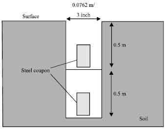 | |
| Fig. 5: | Location of buried coupons |
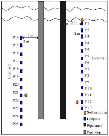 | |
| Fig. 6: | Locations of coupons |
| Table 2: | Various types of NDT inspection techniques |
 | |
Since the experiment is conducted under worst-case scenario, therefore it is of importance to keep a minimum ground distance of 5 m between the pipeline route and the hole. This is to deter unnecessary protection upon buried coupon by stray current sourced from Cathodic Protection system (CP) on the operated line.
The samples afterwards will be retrieved off the site once every three month for the whole period of two years. The retrieved samples must not be restored since the sample has to be taken back to laboratory for cleaning and metal loss weighing, hence disturbs the original condition of the sample. Therefore, the coupon samples must be prepared under strict quality control to assure the uniformity of the samples in terms of dimension and weight. By doing so, time dependent-metal loss data which is not recorded from the same sample every time weighing process is done can be used to develop a relationship of corrosion dynamic against time with minimum error.
The steel coupons are originated from actual segment of steel pipe with grade ranged from X42-X70. The oxy-cutter is used to cut the pipe segments into small coupons. The edge of pipe segment which severely affected by excessive amount of heat during cutting process is then removed using cold-cutting technique leaving unscathed area for coupon preparation. Coupon sized of 80 cm x 60 cm can then be produced using cold-cutter device. The existing coating must be removed using grinder machine so that the coupon can be tested under worst condition of corrosion attack.
Data sources: Real inspection data of corrosion defects can be acquired from on site periodical inspection activities. The required data can be classified as a secondary data, collected by professional inspection vendor. Table 2 displays the types of NDT tools used to inspect corroding structures and the collected data from these NDT tools may be useful for this research. The inspection data and previous record maintenance kept by the pipeline operators are vital to give an indication on the historical record and current condition of the investigated pipelines. The selection of area from which the soil samples will be collected depends on the maintenance record and inspection data.
On-site measurement: On site measurement is a requirement to systematically record in situ soil parameters during field work and later compared with the secondary results from laboratory soil testing for verification. Mobile apparatuses with high accuracy and minimum limitation are needed to measure water content, salinity, pH, conductivity and resistivity of fresh soil. The measurement of water content on site is crucial. This is due to the fact that the fresh soil used to measure water content must not be exposed to environment more than 24 h prior to the testing. Failure to comply means, the measurement of water content via lab testing is considered not valid. If the soil sample is not feasible to reach laboratory within 24 h, therefore a mobile moisture content apparatus is needed to record the reading. The recorded parameters can then be used to develop empirical relationship between metal loss and soil content.
Expected results: The proposed new techniques in soil-corrosion study for underground pipelines is designed to assist researchers in collecting real-time metal loss data under worst corrosion condition using steel coupon similar to the steel grade of operated line. The data, if properly analysed and combined with laboratory data, can be fully transformed into empirical information for the following benefits;
| • | Corrosion rates of corroding pipelines for specified materials, locations and conditions |
| • | Simplified external corrosion growth prediction model to be used by industries |
| • | An overall improved interpretation of inspection data and prediction methodology in the integrity assessment of corroded pipelines |
| • | Assist the operators in making accurate decisions on what, when and where of future inspection, repair and maintenance resources to be deployed |
| • | Reduce the overall operating cost of the line |
CONCLUSIONS
A new technique of conducting on site experimental work to measure the real-time metal loss of buried coupon under influence of soil-corrosion factors has been presented. The potential model of external corrosion growth rate with the inclusion of soil factors based on this technique; specifically developed for buried steel pipeline; can be used to evaluate the best corrosion protection scheme to be deployed on the pipelines prior to the installation according to specific site/location. Hence, improving the reliability of the line at a minimal cost and be able to avoid unnecessary inspections in the future. A database of corrosion growth potential for pipeline installation sites can be developed for specific site and soil condition for future reference.
ACKNOWLEDGMENT
The first author is pleased to acknowledge the Ministry of Science, Technology and Innovation, Malaysia (MOSTI) and the Ministry of Higher Education (MOHE) for the support by providing the research funds and scholarship (NSF).
REFERENCES
- Ahammed, M. and R.E. Melchers, 1997. Probabilistics analysis of underground pipelines subject to combined stresses and corrosion. Eng. Structures, 19: 988-994.
CrossRef - Cheuk, C.Y., W.A. Take, M.D. Bolton and J.R.M.S. Oliveira, 2007. Soil restraint on buckling oil and gas pipelines buried in lumpy clay fill. Eng. Structures, 29: 973-982.
CrossRef - Ahammed, M., 1998. Probabilistic estimation of remaining life of a pipeline in the presence of active corrosion defects. Int. J. Pressure Vessels Piping, 75: 321-329.
CrossRef - Nesic, S., 2007. Key issues related to modelling of internal corrosion of oil and gas pipelines: A review. Corrosion Sci., 49: 4308-4338.
CrossRef - Melchers, R.E. and R. Jeffrey, 2008. The critical involvement of anaerobic bacterial activity in modelling the corrosion behaviour of mild steel in marine environments. Electrochem. Acta, 54: 80-85.
CrossRef - Englehardt, G. and D.D. MacDonald, 1998. Deterministic prediction of pit depth distribution. Corrosion, 54: 469-480.
Direct Link - Goswami, T.K. and D.W. Hoeppner, 1995. Pitting corrosion fatigue of structural materials. Proceedings of the ASME International Mechanical Engineering Congress and Exposition, Nov. 12-17, San Francisco, California, pp: 129-139.
Direct Link - Harlow, D.G. and R.P. Wei, 1994. Probability approach for corrosion and corrosion fatigue life. AIAA J., 32: 2073-2079.
Direct Link - Kondo, Y., 1989. Prediction of fatigue crack initiation life based on pit growth. Corrosion, 45: 7-11.
CrossRef - Chen, G.S., K.C. Wan, M. Gao, R.P. Wei and T.H. Flournoy, 1996. Transition from pitting to fatigue crack growth-modeling of corrosion fatigue crack nucleation in a 2024-T3 aluminum alloy. Mater. Sci. Eng., 219: 126-132.
CrossRef - De Waard, C., U. Lotz and D.E. Milliams, 1991. Predictive model for CO2 corrosion engineering in wet natural gas pipeline. Corrosion Eng., 47: 976-985.
Direct Link - Doyle, G., M.V. Seica and M.W. Grabinsky, 2003. The role of soil in the external corrosion of cast iron water mains in Toronto, Canada. Can. Geotechnical J., 40: 225-236.
Direct Link - Osella, A., A. Favetto and E. Lopez, 1998. Currents induced by geomagnetic storms on buried pipelines as a cause of corrosion. J. Applied Geophys., 38: 219-233.
CrossRef - Ferreira, C.A.M., J.A.C. Ponciano, D.S. Vaitsman and D.V. Perez, 2007. Evaluation of the corrosivity of the soil through its chemical composition. Sci. Total Environ., 388: 250-255.
CrossRef - Bullard, S.J., B.S. Jr. Covino, G.R. Holcomb, J.H. Russell, S.D. Cramer, M. Ziomek-Moroz and D. Eden, 2003. Laboratory evaluation of an electrochemical noise system for detection of localized and general corrosion of natural gas transmission pipelines. Paper No. 03371. CORROSION/2003, NACE International, Houston TX. http://www.osti.gov/bridge/product.biblio.jsp?osti_id=821881.
Evans, U Felix Reply
I wish to join your research team, your ideas are quite good.
Hawkar, J Muhammed Reply
Dear sir
I hope you are doing well, I would like to ask about the criteria or standard that have chosen to select the size of coupon that buried in soil.
thanks for your help
Beast regards