
K. Abdelmoudjib
Department of Electrical engineering, Higher School of Technical Teaching and Engineering, BP 1523, El-M’naouer, Oran, Algeria
Journal of Applied Sciences
Year: 2009 | Volume: 9 | Issue: 16 | Page No.: 2955-2961


ABSTRACT
The purpose of this study is to present the diverse possible applications of sensors with digital-fuzzy interface (smart sensor); fuzzy sensors. Concepts will be presented as well as the development of analytical model and qualitative model of the sensor; for the local localization, in the case of strategy reactive by reflex movement, for a mobile robot navigating in the unknown and dynamic environment. The use of these concepts is then illustrated by simulation examples simulating the evolution of the robot in various environments are presented which show, that the most significant problem being, the optimization of the time taken by the robot between perception and the corresponding action. The reactive strategy system, can fixe the direction of the target in a cluttered indoor environment without scanning this environment.
PDF Abstract XML References Citation
How to cite this article
K. Abdelmoudjib, 2009. Interaction with Environment Technical Fuzzy Approach. Journal of Applied Sciences, 9: 2955-2961.
DOI: 10.3923/jas.2009.2955.2961
URL: https://scialert.net/abstract/?doi=jas.2009.2955.2961
DOI: 10.3923/jas.2009.2955.2961
URL: https://scialert.net/abstract/?doi=jas.2009.2955.2961
INTRODUCTION
One notice in industry a clear development of devices that can be defined as robots or manipulating arms at various degrees. The extent of their possibilities, on one hand, the variety and complexity of the movements they can make and on the other hand their ability to respond automatically to external information makes the issue of command, control and perception becomes an important topic of study and research in robotics (Weibing and Di, 1994; Reignier, 1994; Krzystof and Dariusz, 2004. The actual combination or fusion of information in the multi sensors systems for mobile robot has been a particularly active area of research (Li et al., 2004; Sredan Mitrovic, 2006). So that, a robot could be able to adapt itself efficiently to its environment, would be interesting to develop its modelling. The calculator possesses a model of the mechanical articulated system, the model of the environment (Chavant and Colle, 1998); the data on tasks which must be performed and a number of computational resources (strategies and computing) using exteroceptive information (state of the environment), which are obtained from sensors. The robot can grasp its environment and adapt itself (detection of obstacles, controlling position, coercive measures etc). There are many sensors used in mobile robotics. We focus on ultrasonic sensors for their range, one to two meters. They are best suited to the measurement of distance and positioning (Kai and Charles Chang, 1993; Reignier, 1994); moreover, they have relatively less encumbering, compact and inexpensive.
We developed a method of avoidance reflex, based on the artificial potentials fields (Khatib, 1985). Based on a qualitative method of estimation of the configuration of the obstacles obtained from data sensors, this approach takes account on the one hand of the configuration of the obstacles in the robot local space and on the other hand possibilities of the robot avoidance. The developed model is expressed in the form of two indices of constraints characterizing left and right spaces.
The adaptation on line of the qualitative model, allows to increase the strategy robustness and to generalize its field of application to varied environments. We also developed an approach allowing the addition of a tropism in the form of two parameters, speeds and orientation, our algorithm acting as corrector of the principal command.
SENSOR, INTERACTION WITH ENVIRONMENT
The measurements are often done using analogue sensors usually consisting of a conditioning device and a transmitter, the information exchanged between the sensor and controller is in an analogue form. Thus, the controller integrates A/D converters for the measurements and D/A converters for commands (Sredan Mitrovic, 2006; Maki Habib, 2007). The evolution of technology, particularly in the field of microprocessors has led to use these components in the sensors. This innovation was simply to introduce these new sensors as intelligent ones. Robert et al. (1993) proposed a new vision of the sensor in its environment. It is presented as a system that can be defined as a set of subsystems; the basic systems being the transducers and actuators that have a physical interface with the outside world.APPROACH ON THE SMART SENSOR
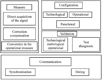
A description in terms of functionality, derived from the white book (Benoit and Foulloy, 1991) sets out the broad lines of the concept. A smart sensor; must above all, make a valid measure. This is then transmitted to the user, who must have previously set the smart sensor which highlights the functionality measure, configuration and communication (Fig. 1) (Chavant and Colle, 1998; Reignier, 1994).
Measurement functionality: A smart sensor, must before all, carry out a validated measurement: the functionality measurement integrates the aspects of metrology and signal processing related to the sensor as well as to the exteroceptive physical variables. It is necessary to add the variables of self-checking, which are associated at the technological measurements that characterize the state of the sensor at a specific time t, the time which ensures a coherent dating of information and models which contribute at various levels of validation of a database.
It is interesting to note that all these sizes can be classified in:
| • | Local variables, characterizing the physical environment of the smart sensor; for example, primary measurement: ambient temperature |
| • | Distant variables characterizing the system environment of the smart sensor, for example; system clock, network occupancy rate and also any information emitted by any other sensor. All these variables contribute to obtain a measurement |
 | |
| Fig. 1: | Smart sensor functionalities |
Validation functionality: Functional measurement must be validated by the taking into account of technological measurements which characterize the correct operation of the smart sensor, so much in term of technology such as measurement of the supply voltage, integrity of the acquisition chain and checking of the good unfolding of an algorithm; that in term of methodology, is a question of testing the coherence of measurement compared to models such as: variation in the measurement extent detection of aberrant measurements in a time series.
Configuration functionality: The functionality configuration includes:
| • | A technological configuration resulting from a whole actions and their validations aiming at integrating the sensor in its physical environment; a functional configuration aiming at returning the sensor measuring and communicating |
| • | An operational configuration aiming at dedicating the sensor to the application |
The functional and operational initial configurations can be modified on the initiative of the operator.
Communication functionality: The functionality communication ensures the exchange of information between the sensor and its environment. It must decode and interpret the orders and messages, which arrive at the sensor and consequently start the adequate actions. It also has in charge the setting of information to transmit from the smart sensor towards the external world.
The Grafcet in Fig. 2 must be supplemented by the test reports analysis; the test request can be activated by the operator or the intelligent sensor itself.
In particular, the tests results, can make lead to:
| • | A stop, possibly associated a corrective maintenance |
| • | A degraded exploitation which will have to be followed of a corrective maintenance |
| • | A declaration, smart sensor out service; associated with the possible delivery of a value with fold what implies a passage by the initial stage |
The smart sensor consists of a sensor, an internal arithmetic unit and an interface of communication; it will deliver either a value but information.
The processor, which is associated for him, makes a pre-treatment and returns information more precise than that provided by a non intelligent sensor.
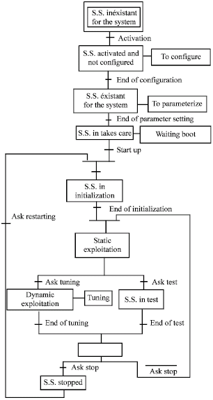 | |
| Fig. 2: | Grafcet state of a smart sensor |
FUZZY CONTROL
The fuzzy set theory was introduced by Lee Chuen (1990) and Zadeh and Yager (1992), it reasoned on knowledge which can be at the same time fuzzy (badly described) and dubious whose validity is subjected to a fuzzy control is a method of adjustment that tolerates a weak knowledge of the process, it finds its efficiency in the badly defined and complex processes which can be controlled by a human operator, specialized, without knowledge of their basic dynamics. The structure of a fuzzy controller is made of four parts (Glonnerec, 1996).
Database and rule: This block contains information concerning the applicability and the operation of the system in the fuzzy controller, the dynamic behavior of the systems is described by linguistic rules of the form <<if (conditions) then (consequences)>>, generally deduced from knowledge by an expert of the system (Abdelmoudjib, 1999). This coding is mostly used because of the causality that it expresses.
Fuzzification: Here, an actual value of a state variable is transformed into a variable compatible with the representation of the sets which one will be chosen. The phase of fuzzification consists of making a partition of the field definition of the entries in fuzzy intervals. This partition is used then for the linguistic description of the relations between entries and outputs.
Fuzzy inference: Here, one determines the degree of validity of the rules brought into play starting from the state variable fuzzified and one deduces a fuzzy conclusion.
Défuzzification: The fuzzy conclusion is translated into likely no fuzzy ordering of controller suitably the process.
MODELLING
In this study, Khatib (1985); the strategy which we develop is based on the artificial potential field for the obstacles avoidance and privileges the advance of the robot systematically. Any obstacle being located at the back the robot is being regarded as moving away relative to the robot and does not present any more danger of collision. The obstacles are not reconstituted in the local plan of the robot because it does not know their geometries, for the robot these are modelling by segments whose configuration is approximate. It is characterized by its orientation and its position in the relative reference mark of the robot. In addition a mobile obstacle will be regarded as static at the sampling moment T in the reference mark of the robot, the tactics of displacement will not be different, because the dynamics of the scene is being represented between two sampling moments (T and T+1).
In addition to the position control, it is only a question of detecting or not, the presence of an object; relevant information is the distance. One chooses the ultrasonic sensors for their low cost and they provide information of distance to the price of a simple treatment, which is significant in the real time processing. The analysis of the data is done according to the three sides of the robot (front, left, right).
The calculation of the distance is obtained from the first obstacle met by the ultrasonic wave in a given direction (principal direction of the beam is carried out by time measurement of flight of the emitted wave); interval of time between the emission beginning and the reception of the first echo.
Analytical model: Controller takagi-sugeno the general form of the rule is written (Takagi and Sugeno, 1985):
(1) |
where, fij is an analytical function of the controller inputs x and y. A particular case of rules of takagi-sugeno is that the functions fij are constant. The preceding rule becomes:
| (2) |
where, Sij is a fuzzy singleton corresponding to the Rij rule. Method of inference being method of individual inference, each rule is treated individually.
The treatment can be described by 3 stages:
| • | The calculation of membership of the entry to the vague sets which make the antecedent of the rule (fuzzification) |
| • | The weighting of the whole of exit describing the rule consequent by the weight of this rule |
| • | The balanced values of the exits are aggregate to give the exit total value |
If one takes again the Rij rule the degrees of membership of the entries x0, y0 to the fuzzy values.
The weight or rate of the rule excitation is then:
| (3) |
The individual inference gives for each rule the fuzzy exit:
| (4) |
where, U being composed of singletons; we have:
| (5) |
The exit value u0 value after défuzzification is then:
| (6) |
The calculation of U0, on all the field of excursion of (x, y) gives the analytical model.
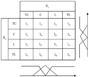 | |
| Fig. 3: | Rule for index collision risk controller |
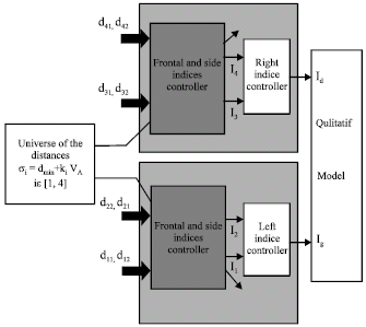
Qualitative model: The qualitative model represented by the data of the two collision risk indices in half spaces right and left, allows choosing an avoidance movement. when obstacles occurred.
This movement can be carried out in function of the model, in the form of a linear velocity (advances) and an angle of rotation (orientation). Induced displacement must tend to a reduction in the greatest risk.
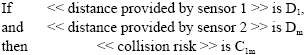
The base of rules of the controller of the collision risk index noted I, is obtained from the analysis of the data sensors and results from knowledge qualitative of the kinematics possibilities of the robot. They are given under form:
One notes this rule Rlm and Ilm linguistic variable characterizing the collision risk is associated with Rlm (l, ∈ [1, 4]). Ilm is the consequent one in the Rlm rules. What gives us, the tables of the form rules following. Figure 3 developed on this model gives the index collision risk for the half right and left spaces.
The base of rules of the collision risk index controller offers 16 different possibilities; who indicate the possible collision risk of the robot with its environment. The stability of the robot is reached for a symmetrical model, not in geometrical term, but with respect to the collision risk with the environment.
A module of orientation control consists of a fuzzy controller whose inputs are the Ig, Id, components of the qualitative model; and they will also be used as inputs, for the linear speed controller.
The two constraint indices of left and right spaces, give a qualitative representation of the robot’s mobility; and forms the doublet (Ig, Ig).
 | |
| Fig. 4: | Qualitative model algorithm (Ig, Id) |
 | |
| Fig. 5: | Algorithm of calculation (dij) |
Id is the défuzzified output of the left index controller; and Ig is the défuzzified output of the right index controller (Fig. 4).
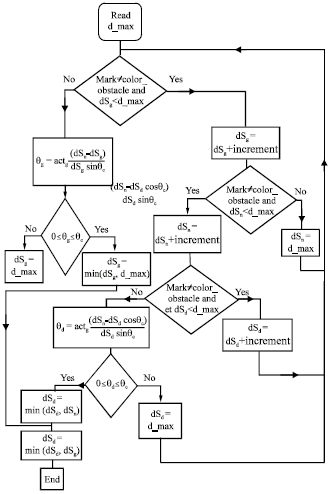
Measurements of distances are determinates by the calculation algorithm (Fig. 5), which simulates the operation of the ultrasound sensors
SIMULATION
We take for speed of the robot Vnom = 2 m sec and an acceleration maximum of 1.5 m sec-2. One chose:
| (7) |
| (8) |
The membership functions of the variable λE are fuzzy singletons which distribution is defined in a heuristic way.
λE = 0 corresponds to a space charged with obstacles: (Id = 0; Ig = 0), which causes the robot to stop
λE = 1 corresponds to an open spac:
(Id = 3; Ig = 3) which gives a maximum speed
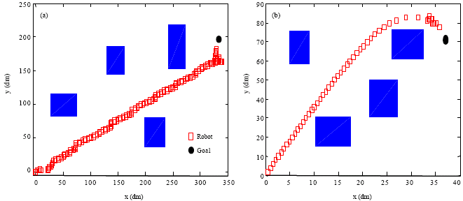
Figure 6a and b show the results of the simulation of the behaviour of the robot where fixed obstacles of various dimensions, are placed.
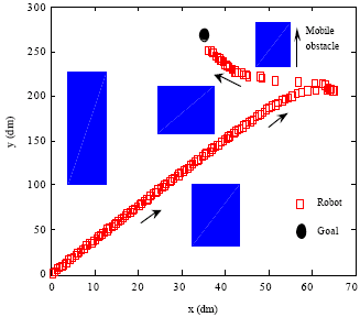
Figure 7 shows the simulation of the behaviour in an Unknown environment together with another mobile obstacle. This example, show the difficulties characterizing the performances of a reactive system.
Indeed a number of parameters intervene, like the rate of obstruction of space; the robot’s relative configuration; the mobile obstacle; their respective speeds.
Each behaviour is consisted a base of fuzzy rules, a controller allows inferred an action starting from sensory information. Membership functions of the variable λ are fuzzy singletons whose distribution is defined in a heuristic way.
Method of fusion actions, depends on the trajectory followed by the robot. Indeed, the behaviour of the robot can be radically different according to criteria’s set up.
The choice of the smart sensor concept allows low level management of information sensor and to reduce the main program of the behaviors management.
Based on a qualitative method of estimate of the obstacles configuration starting from the data sensors, this approach takes account on one hand of the obstacles configuration in the robot space and possibilities of avoidance of robot on the other hand. The adaptation on line of the qualitative model makes it possible to increase the robustness of the strategy installed and to generalize its field of application to varied environments.
 | |
| Fig. 6: | (a, b) Fixed obstacles avoidance |
 | |
| Fig. 7: | Mobile obstacle avoidance |
CONCLUSION
As a whole the algorithm of simulation shows good performances for our qualitative model. There is however a case of failure for a singular situation, inherent to present model; however a solution to manage this situation would be introduce a bias in orientation.
Present major contribution can be summarized as the proposed reactive strategy system; can fixed the direction of the target in a cluttered indoor environment without scanning this environment.
Based on the good theoretical predictions, we can affirm that the robot will be able to self-navigate toward the target, avoiding the obstacles that occlude the path to the target.
Present future effort includes an algorithm to minimize time between perception and action and the recovery of the distorted signals for efficient localization and the enhancement of self-navigation with other aiding sensors, like Rfid system (Zhou, 2007; Takayuki et al., 2007).
REFERENCES
- Habib, M.K., 2007. Real time mapping and dynamic navigation for mobile robots. Int. J. Adv. Robot. Syst., 4: 323-338.
Direct Link - Mitrovic, T. S., 2006. Design of fuzzy logic controller for autonomous garaging of mobile robot. J. Automatic Contr. Univer. Belgrade, 16: 13-16.
Direct Link - Takagi, T. and M. Sugeno, 1985. Fuzzy identification of systems and its applications to modeling and control. IEEE Trans. Syst. Man Cybern., 15: 116-132.
CrossRefDirect Link - Krzystof, K. and P. Dariusz, 2004. Modeling and control of a 4 wheel skid-steering mobile robot. Int. J. Applied Math. Comput. Sci., 14: 477-496.
Direct Link - Li, T.H.S., S.J. Chang and W. Tong, 2004. Fuzzy target tracking control of autonomous mobile robots by using infrared sensors. IEEE Trans. Fuzzy Syst., 12: 491-501.
CrossRefDirect Link