
G.K. Mojtaba
Department of Civil Engineering, Islamic Azad University, Behbahan, Iran
B.G. Abbas
Department of Civil Engineering, Shahid Bahonar University, Kerman, Iran
Journal of Applied Sciences
Year: 2009 | Volume: 9 | Issue: 12 | Page No.: 2325-2329


ABSTRACT
In this study, effect of two types of groynes; bar and blade types on river outer bank protection has been investigated by a physical model. Model includes a canal with 73 cm width, 45 cm height and 115 cm long with two intakes and four bends of 45, 90, 135 and 180°. Experiments have been performed on the 45° bends of model. Results show that permeable groynes in both bar and blade types are effective in outer bank protection. Comparison of two bar and blade types groynes show that blade-types groynes are more economical, but their disadvantages are scour around the groynes. Finally combination of two bar and blade types groynes can be the solution of this problem.
PDF Abstract XML References Citation
How to cite this article
G.K. Mojtaba and B.G. Abbas, 2009. Effect of Groynes Opening Percentage on River Outer Bank Protection. Journal of Applied Sciences, 9: 2325-2329.
DOI: 10.3923/jas.2009.2325.2329
URL: https://scialert.net/abstract/?doi=jas.2009.2325.2329
DOI: 10.3923/jas.2009.2325.2329
URL: https://scialert.net/abstract/?doi=jas.2009.2325.2329
INTRODUCTION
River banks erosion is one of the main sources of sediment. Many methods such as gabions, submerged vanes and groynes have been used to protect the river banks especially at river bends. Hydraulics of flow in river bends has been considered by many researchers. Yen and Lee (1965) has been considered the hydraulics of flow and shear stress distribution of river bends with constant bed. Engelund (1974) has been investigated two dimensional river bed variations. Bridge (1992) has been considered the interaction between fluid flow, sediment transport, bed topography and sediment size at river bends. Nagata et al. (2000) have been considered the changes of bed in rivers with banks made of erodible materials. Uijttewaal et al. (2001) through a scaled model of the Dutch river wall have been studied the exchange process between a river and its groyne fields, with emphasis on the characteristics of the exchange process in relation to turbulent motions.
Groynes can be considered in two types: permeable and impermeable. Permeable groynes usually made of materials such as wood and Bamboo, while materials such as rocks, gravel and gabions can be used for impermeable groynes. Based on the design conditions they can be used in two floating and unfloating states (Przedwojski et al., 1995). The distance between groynes is dependent to the river width, groyne length, flow velocity and angle of groyne to the river bank (Przedwojski et al., 1995). Uijttewaal (2005) through a 1:40 scaled model of Dutch waal river has been considered four types of groynes, include: type A (impermeable groyne with slope of 1:3 at the groyne head), type B (impermeable groyne with slope of 1:6 at the groyne head), type C (permeable groyne) and type D (combination of types B and C). Uijttewaal (2005) reported that, groynes type B with smoother slope of head can prevent creation of vortex and produces flow with low turbulence. In groynes type C, flow passes through bars without creation of vortex. Groynes type D create some fluctuations in velocity and causes instability of flow. Weitbrecht and Jirka (2001) have been performed some experiments on a flume 20 m long, 1.8 m width and adjustable slope with flow velocity of 16 m sec-1 and 4.6 cm depth. They used the ratio of w/L = 0.4 (w is the groyne length and L represents the distance between groynes) and different angles of groyne with bank (α = 90, 64 and -64°). In another experiment, Weitbrecht et al. (2004) used this model and performed experiments for different ratios of w/L (w/L = 0.17, 3.5). Experiments on geometries that more realistically resemble groyne fields are scare and mostly restricted to field measurements (Brinke et al., 1999). In addition to field measurements, the flexibility in geometry and control of flow parameters make laboratory experiments of key importance for understanding the physics behind water motion and the associated exchange process (Chen and Ikeda, 1997). Substantial experimental work on exchange processes has been performed on model harbors, clearly because of its relevance regarding dredging problems (Westrich and Clad, 1979; Booij, 1989; Langendoen et al., 1994; Altai and Chu, 1997). In the present study using a physical model, effect of two types of groynes; blade and bar types on canal outer bank protection has been considered.
MATERIALS AND METHODS
A physical model was built in September 2007 at the Shahid Bahonar University of Kerman in an area of 600 m2. This model consist of a rectangular channel of 115 m long, 0.73 m wide and 0.35 m height with four bends of 45, 90, 135 and 180° and two intakes of 45 and 90° (Fig. 1). To construct the model, a 10 cm layer of cultivated soil was removed and the ground surface was compacted. Base of model at 2.2 m width graded by a teodolit camera and compacted. Then, 10 cm concrete of 150 kg m-3 cement was covered over the compacted surface. The canal sidewalls were built at a distance of 75 m from each other and 40 cm height. The canal bottom was coated with a 5 cm concrete of 250 kg m-3 cement. Inside of canal sidewalls were coated by a 1 cm layer of fine mortar to become uniformly smooth (Fig. 2). The bottom slope of model was regulated equal to 0.0025. Water was supplied through a well by an electrical pump and convey to the model by a 70 m long canal. A 90° triangular weir made of 0.55 mm thickness of galvanized plate was established at the end of the model to measure the flow rate. A 10 cm layer of sand with a median diameter of 1.6 mm and geometric standard deviation of δg = 3.88 was covered on the bottom of model. Hydraulic parameters of flow through the experimental canal were presented in Table 1.
Experiments were performed on the 45 degree bend using groynes with different percentage of opening. Two types of iron-bar and iron-blade groynes were used through experiments (Fig. 3a, b). Groynes were made such that the distance between bars or blades was adjustable to fix a specific percentage of openings.
Required time period for each experiment was measured equal to 2.5 h. After this period, canal bed will reach an equilibrium such that, no sediment transport occurs. As a result, for more confidence, a time period of 3 h foe each experiment has been specified. After this period, inflow to model has been shut down and bed elevations were measured using Sand Surface Meter WH-406 with commercial name of KNEK, made of Japan with 0.5 mm accuracy. Measurements have been done from 30 cm before the bend to 120 cm after the bend along the straight canal. The measured region was divided into 13 equal parts at wide side and 24 parts longitudinally, such that a network with 312 nodes has been produced and measurements were performed at these notes (Fig. 4).
First experiment has been performed without groynes to obtain basic data for comparison. Second experiment has been performed using a single bar-groyne of 70% opening. Third experiment has been performed using two bar-groynes of 63% opening at a distance of 150 cm from each other. Experiments have been continued using bar-groynes and blade groynes of different opening percentages and distances between them.
 | |
| Fig. 1: | Plan view of model |
 | |
| Fig. 2: | Details of canal cross-section (section A-A of Fig. 1) |
 | |
| Fig. 3: | Two types of groynes (a) blade and (b) bar types |
| Table 1: | Hydraulic parameters of the physical model |
 | |
Overall 21 experiments with bar-groynes, 2 experiments with blade-groynes, one experiment with a mixed bar and blade groynes have been performed.
Opening percentage of groynes can be computed by the following equation:
(1) |
where, n represents number of bars or blades in a groyne, b is the diameter of a bar or effective width of a blade and w is the length of groyne.
 | |
| Fig. 4: | Longitudinal and wide side sections of canal |
RESULTS AND DISCUSSION
Results of first experiment which has been performed without groyne show a severely scour at the outer bank of bend (Fig. 5). It is started a small distance after the beginning of bend (×5 of Fig. 3) and continued to the downstream of the bend (×19 of Fig. 3).
Second experiment has been performed using a single groyne of 70% opening. This groyne was installed at the x7 station. Results of this experiment show that the eroded zone was moved towards the downstream of groyne (Fig. 6).
Next experiment has been performed using two groynes of 63% opening with 150 cm distance between groynes. Results show that erosion of the canal outer bank at the groyne field was reduced. Severe erosion at stations of 150 and 300 cm of Fig. 7 should be related to the groynes pits. In continuation, experiments have been performed using groynes of 63, 70 and 66% openings with 50, 70, 90 and 110 cm distances between successive groynes and 73% opening with 50, 75, 90 and 110 cm distances between successive groynes (Fig. 8). Groynes have been installed perpendicular to the canal outer bank in submerged conditions through whole experiments. Regression analysis of data of Fig. 8 results Eq. 2 to 5:
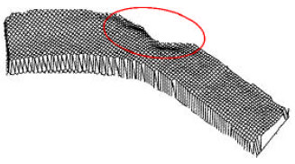 | |
| Fig. 5: | Erosion of bend outer bank without groyne installation |
 | |
| Fig. 6: | Longitudinal profiles of bed with and without groyne installation |
 | |
| Fig. 7: | Longitudinal profiles of bed with and without groyne installation |
(2) |
(3) |
 | |
| Fig. 8: | Maximum erosion depth (dh) as a function of groynes distance (Ls) for groynes of different percentage of openings (n) |
 | |
 | |
| Fig. 9: | Sediment depth (h-m) as a function of canal width (B cm) (a) section 3, (b) section 7, 8 section 11 and (d) section 15 |
(4) |
(5) |
In which, dh represents the maximum scour depth, h0 is average depth of water, Ls is distance between successive groynes, l is distance between groynes bars and w is the groyne length (w = 29 cm in these experiments).
Results of experiments using blade-type groynes of 45% opening with 90 cm distance between successive groynes have been compared with similar bar-type groynes. Figure 9 shows that blade-type compares to bar-type groynes creates more scour at the center of canal.
CONCLUSION
Application of groynes reduce scour at the canal outer bank significantly. Among different types of groynes, experiments show that application of permeable groynes resulted better scour protection compare to the two other types. Groynes with more permeability results less scour, but the groyne fields should be reduced, as a result, the number of groynes in a specified length of river should be increased which is not economical. Application of groynes with variable permeability across the length, result better scour protection at the canal outer bank.
Application of blade-type groynes can be more effective in bank protection, but erosion at the center of canal increases. So, application of combined bar and blade type groynes result better protection of river bend outer bank.
REFERENCES
- Altai, W. and V.H. Chu, 1997. Retention time in a recirculating flow. Proceedings of the Environmental and Coastal Hydraulics: Aquatic Habitat the 27th Congress of the International Association of Hydraulic Research, August 10-15, 1997, American Society of Civil Engineers, New York, USA, San Francisco, CA, pp: 9-14.
- Bridge, J.S., 1992. A revised model for water flow, Sediment transport, bed topography and grain size sorting in natural river bends. Water Resour. Res., 28: 999-1013.
Direct Link - Chen, F.Y. and S. Ikeda, 1997. Horizontal separation flows in shallow open channels with spur dikes. J. Hydrosci. Hydraulic Eng., 15: 15-30.
Direct Link - Engelund, F., 1974. Flow and bed topography in channel bends. J. Hydraulics Division, 100: 1631-1648.
Direct Link - Langendoen, E.J., C. Kranenburg and R. Booij, 1994. Flow patterns and exchange of matter in tidal harbours. J. Hydraulic Res., 32: 259-270.
CrossRefDirect Link - Nagata, N., T. Hosoda and Y. Muramoto, 2000. Numerical analysis of river channel processes with bank erosion. J. Hydraulic Eng. ASCE, 126: 243-252.
Direct Link - Uijttewaal, W.S.J., 2005. Effects of groyne layout on the flow in groyne fields: Laboratory experiments. J. Hydraulic Eng. ASCE, 131: 782-791.
Direct Link - Uijttewaal, W.S.J., D. Lehmann and A. Mazijk Van, 2001. Exchange processes between a river and its groyne fields: Model experiments. J. Hydraulic Eng. ASCE, 127: 928-936.
CrossRef - Weitbrecht, V., W.S.J. Uijttewaal and G.H. Jirka, 2004. A random walk approach for investigating near-and far-field transport phenomena in rivers with Groyne fields. Proc. River Flow Naples, 2: 1157-1166.
Direct Link
Shihab Reply
I'm a thesis student. I'm working in aproject "The effectiveness of the different type of groyne systems in a physical model study". It will be very helpful if you share the thesis with me.
Thanks.