
Y.B. Motlagh
Faculty of Civil Engineering, Technical University of Babol, Tehran, Iran
Y. Gholipour
School of Civil Engineering, University of Tehran, Iran
Gh. Ebrahimi
Faculty of Natural Resources, University of Tehran, Iran
M. Hosseinalibeygi
Department of Civil Engineering, University of Mazandaran, Iran
Journal of Applied Sciences
Year: 2008 | Volume: 8 | Issue: 21 | Page No.: 3887-3894


ABSTRACT
The aim of this study is strengthening the old wood members in historical buildings with new innovative technology, which have lost parts of their strength due to heavy loads, loading time factor, effects of extreme humidity or insects attack. Most of the ancient buildings throughout Iran have been constructed mainly by wooden members. Some of the structural members in such a valuable buildings are partially defected. Therefore, it seriously needs to be repaired or rehabilitated in order to maintain in proper strength. Present research is focused on strengthening the old wood beam members sampling from non-essential sections of historical buildings with Glass Fiber Reinforced Polymer (GFRP) composite materials. A three-point loading test was used to study the behavior of the beam subjected to gradual static load under different configurations of reinforcement. The load-displacement response, ultimate strength, modulus of elasticity and the mode of failures were evaluated. The experimental results have shown an improvement in load capacity, strength and stiffness of hybrid if compared with un-reinforced samples. At the end, the experimental and analytical results were compared with each other.
PDF Abstract XML References Citation
How to cite this article
Y.B. Motlagh, Y. Gholipour, Gh. Ebrahimi and M. Hosseinalibeygi, 2008. Experimental and Analytical Investigations on Flexural Strengthening of Old Wood Members in Historical Buildings with GFRP. Journal of Applied Sciences, 8: 3887-3894.
DOI: 10.3923/jas.2008.3887.3894
URL: https://scialert.net/abstract/?doi=jas.2008.3887.3894
DOI: 10.3923/jas.2008.3887.3894
URL: https://scialert.net/abstract/?doi=jas.2008.3887.3894
INTRODUCTION
Before the era of steel and concrete technology, wood was the most common structural material in residential, public and industrial buildings throughout Iran, particularly in the Northern provinces which own commercial forest. Majority of the existing ancient buildings in this country are aged over one century, which some of them are registered as historical heritage and are still standing in a good functioning shape. At the time being, conservation and restoration of these valuable buildings are most concern of Iran`s office of historical heritage. Inappropriate rehabilitation of the defected structural elements in historical buildings greatly influence on their beauty and dignity (Fig. 1).
Over the past 40 years, both Fiber Reinforced Polymer (FRP) and non-FRP materials have been used to reinforce wooden structural members.
During the last two decades, a special prefabricated Fiber Reinforced Polymer (FRP) composite was developed to repair and retrofit wooden elements in field.
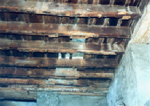 | |
| Fig. 1: | Repair of old stringers with traditional methods |
The advantages of these reinforcing materials lie in their low weight density, high tensile strength and resistance to corrosion. According to the recent investigations, FRP materials have been successfully used to strengthen existing structural members. Svecova and Eden (2004) tested timber beams reinforced with GFRP dowel bars as shear reinforcement as well as flexural bar to control the tension failures observed in some of the specimens. Amy and Sevecova (2004) presented an economical rehabilitation scheme to strengthen creosote-treated dapped timber beams in both flexural and shear with glass fiber reinforced polymer bars. The results of study showed improvement in both flexural strength and shear strength. Borri et al. (2005) presented a method for flexural reinforcement of old wood beams with CFRP materials. Mechanical tests on the reinforced wood showed that external bonding of FRP materials may increase flexural stiffness and bending capacity. Corradi et al. (2006) presented in-plane shear reinforcement of wood beam floors with FRP. Buell and Saadatmanesh (2005) presented an investigation on reinforcement timber bridge beams with a single CFRP. It was reported a 69% increase of the bending strength if compared with control beam and a compression failure mode. Calderoni et al. (2006) presented flexural and shear behavior of ancient chestnut beams under both experimental and theoretical evaluation. The results certified that the simplified methods commonly used to evaluate the bearing capacity of wooden beams can be safely applied to ancient structural members. Corradi and Borri (2007) presented a study on Fir and Chestnut timber beams reinforced with GFRP, which the test results showed that the reinforced beams produced strong increase in flexural stiffness and strength. Schober and Rautenstrauch (2007) submitted a study on reinforcing techniques for restoration and strengthening of existing timber floors under bending loads. The tests have demonstrated that the arrangement of the reinforcement and the stiffness of the materials transmitting the loads, i.e., wood, CFRP and the bonding agent, were of decisive influence for the overall strength of the specimen.
The purpose of this study is to present a new innovative technology for rehabilitation of the old wooden members in the field, through testing small size of wooden members and comparing the experimental results with numerical calculation in order to be used in historical buildings by means of Glass Fiber Reinforced Polymer composite (GFRP) sheets.
MATERIALS AND METHODS
Wood materials: This experimental test is based on more than 50 specimens of ancient native Hackberry. These specimens have been obtained from newly replaced and crushed structural elements of a historical building, located in town of Babol, near Caspian Sea, built up almost 150 years ago. Because of the limitation of obtaining enough old wood for tests and also the major defects present in the main wood, like longitudinal splitting, cracking, degraded zones and holes due to nailing and insect attacks, the samples were obtained in size of 25x25x410 mm and tested as a secondary method under ASTM D-43 for small clear specimens of reinforced timbers.
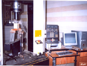 | |
| Fig. 2: | Static bending test assembly |
| Table 1: | Mechanical characteristics of the reinforcing materials |
 | |
The experimental tests were preformed in mechanical laboratory of Faculty of Natural Resources of Tehran University in Karage during May 2006.
GFRP materials: In the recent years FRP has been used as a compatible reinforcement material for timbers and plywood. The physical/mechanical/chemical properties of the FRP are very versatile. The FRP may be engineered to match and complement the orthotropic properties of wood; consequently, incompatibility problems between the wood and the reinforcing FRP are minimized. The unidirectional Glass Fiber-Reinforced-Polymer (GFRP) was used having the physical and mechanical characteristics reported in Table 1.
Resins: The adhesive or glue used in this test was Mac epoxy resin, which consisted of two parts, resin and hardener mixed with a ratio of 3:1 in volume. The mechanical properties of epoxy resin are reported in Table 1.
Test set-up: In this experimental investigation, three- point loading tests were performed as shown in Fig. 2 according to ASTM D-143 for finding out the flexural strength. The simply supported test method was selected to simplify the experimental setup. The wood specimens were supported at the butt and the tip and the load was applied at the center through a bearing block to the tangential surface nearest the pith.
| Table 2: | Mean dimensions of mid-span for timber beams reinforced with GFRP |
 | |
The span`s length between the two supports was Ls = 360 mm which the total length of the specimen was L = 410 mm. These spans were established in order to maintain a minimum span-to-depth ratio of 14. Both supporting knife edges were provided with bearing plates and rollers of such thickness that the distance from the point of support to the central plan is not greater than the depth of the specimen. The knife edges were adjustable laterally to permit adjustment for slight twist in the specimen.
During the process of loading, the experimental responses were transferred to a set of computer that was programmed to register and analyze all data received through a load cell which was connected to the Instron testing machine as shown in Fig. 2. The bending tests have been carried out for a series of control (un-reinforced) beams and for GFRP reinforced beams with varying area fraction of fiber reinforcement as shown in Table 2. The mid-span deflection, ultimate strength and modulus of elasticity have been measured automatically by means of a load cell attached to the loading devices.
RESULTS AND DISCUSSION
Control specimens: In this flexural investigation, at first, three different types of more common un-reinforced woods were tested as reference samples in order to obtain the baseline response. These woods were Hackberry, Oak and Elm, which their experimental results are shown in Table 3. It clarifies that under the same conditions of testing; the ultimate strength and failure load of Hackberry is greater than those of Oak or Elm.
According to the field of investigation, Hackberry wood was the most common structural elements in a high percentage of ancient buildings; therefore this wood has been selected for the study. The results of the test for control specimens are shown in Table 4. Besides, Fig. 3 exhibits the load-displacement relationship and the behaviors of linearity up to failure for all control specimens.
In this test, the mid-span deflection, load capacity, modulus of elasticity in range of the 25 and 75% of elastic region and the mode of failure were evaluated.
| Table 3: | Experimental results of un-reinforced wood under bending test |
 | |
| Table 4: | Experimental results for control samples |
 | |
 | |
| Fig. 3: | Load-displacement response for five samples of control specimens |
GFRP-wood hybrids: In this case, the reinforcement of wood, with glass fiber polymer caused a considerable increase in strength and stiffness under bending test, as shown in Table 5. The load-displacement curves for different schemes of reinforcement are shown in Fig. 4a-e.
From Fig. 3, 4a and b, it can be found that the behavior of load-displacement for all of the control specimens and low composite products are rather liner up to failure point, but for those with more than three layers of reinforcement, the linear behavior changes into nonlinearity as shown in Fig. 4c-e.
The samples under test experienced either a brittle tensile collapse or a ductile compressive failure. Although both unreinforced and low composite products failed in tension side, but an abrupt collapse was observed in unreinforced ones, while all of the low composite products failed rather ductile as shown in Fig. 5a and a partially ductile compressive failure followed by peeling or debonding of GFRP in tension side occurred for the case of three layers of reinforcement (Fig. 5b). In addition, full ductility was exhibited for the case of three layers of GFRP mounted on tension side and one layer on compression side as shown in Fig. 5c.
Results have shown that the effect of GFRP composite reinforcement on the upgrading the mechanical properties of GFRP-wood hybrid is positive.
     | |
| Fig. 4: | Load-deflection curves for five specimens of different configurations of GFRP-wood hybrids, (a) one layer reinforcement on tension side, (b) two layers reinforcement on tension side, (c) two layers reinforcement on tension side and one layer on compression side, (d) three layers reinforcement on tension side and (e) three layers reinforcement on tension side and one layer on compression side |
In all of the experimental cases, there was a considerable amount of increase in the strength and stiffness of the reinforced specimens if compared with control ones. The most effective results in GFRP-wood hybrid were obtained when the specimens were reinforced with three layers of GFRP on the tension side and one layer on compression side as shown in Fig. 6.
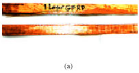 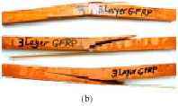 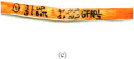 | |
| Fig. 5: | Different types of failure for different wood-hybrid, (a) brittle tensile failure, (b) partially ductile failure followed by sudden break in tension side and (c) full ductile failure in compression |
 | |
| Fig. 6: | Results of different reinforced configurations of GFRP-wood hybrids |
| Table 5: | The mean value of test results of different reinforced schemes of wood- GFRP hybrid |
 | |
In this case, the maximum increase in load capacity, strength and stiffness were 57.1, 31.26 and 9.61%, respectively if compared with unreinforced specimen as shown in Table 5.
Analytical solution of the reinforced wood-GFRP hybrid: According to the test results, the behavior of stress-strain relation is nearly linear up to 75% of load capacity and from there it becomes rather nonlinear. So, if it is assumed that the following relation is accepted.
The stress due to bending moment can be obtained through the equation:
σ = (Me/cS) | (1) |
where, Me is the bending moment of the element, S is the section modules and c is a coefficient that takes into account the timber quality. This approach can be applied for calculation of bending stresses in the reinforced element by substituting Se as equivalent section modules that can be obtained by coefficient η as follows:
η = Efrp/Ew | (2) |
Nonlinear approach: The numerical model takes into account the simultaneous presence of both top and bottom reinforcement of the section, as shown in Fig. 7. According to the law of Bazan-Buchanan the stress and strain in compression side is elastic-plastic and in tension side is linear elastic (Bazan, 1989). Assume the failure not reach to the composite material; it is possible to reduce the study of the problem to two failure cases.
| • | Attainment of limit strain in compression region εcwu |
| • | Attainment of limit strain in tension region εtwu without exceeding limit in the compression region |
 | |
| Fig. 7: | Strain and stress distribution on reinforced wood section |
In both case, from the condition of equilibrium it follows that
Σ F = 0 | (3) |
F1 + F2 + F5 = F4 + F3 |
where, the forces in the compression region are:
 | (4) |
and forces in tension side are:
 | (5) |
where, AfrpC and Atfrp represent the composite area in compression zone and ension region.
The preservation of plain sections, confirmed in several experimental results will be assumed for the congruence equation (Borri et al., 2005).
εCw/y = εtw/(h-y) = εCo/y(1-k) = εtfrp/(h+d-y) = εCfrp/(y+d`) | (6) |
From these equations and for the stress-strain law of material it is possible for each failure case to find the position of the neutral axis (y) and the value of the ultimate bending moment capacity of the section.
In particular, the Bazan-Buchanan law can be expressed as follows:
 | (7) |
where, m represents the slope of the plastic branch of the Bazan-Buchanan law:
m = (σCo - σCwu)/(εCou - εCo) | (8) |
The Eq. 7 can be modified to take into account the possibility of having different elastic modulus in tension and compression zone of the section. In effect, preceding studies on the material indicate that in an overwhelming number of cases, the difference between the two modules is almost negligible with respect to other simplifications assumed.
With regard to FRP materials the generic stress-strain relationship is:
σCfrp = ECfrp. εC frp σtfrp = Etfrp. εt frp | (9) |
which, describe a linear elastic behavior of the two materials. Using Eq. 2 to 9, it is possible to find the neutral axis equation for each assumed failure case. If the failure is reached due to the complete plasticization of the compression region with ultimate strain εCwu, then the neutral axis equation becomes:
σCoy2(1+α-αδ)- Ew εCo(h-y)2 +2ρfrpC EfrpC bhεCwu (y+d`) -2ρfrpt Efrpt hεCwu(h+d-y) = 0 | (10) |
Where:
α = σCwu/σCo, β = εCo/εCwu | (11) |
are Bazan-Buchanan parameters and
ρfrpC = AfrpC/bh, ρfrpt = Afrpt/bh | (12) |
where, ρ is the area fraction for the two composite materials applied in the compression and tension areas.
Then if the tension failure occurs, the neutral axis equation is expressed as follow:
y (2σCo- Φ ((εtwu/(h-y)-εCo)))+y(εCo ((h-y)/εtwy)) H( Φ ((εtwuy/(h-y)-εCo)-σCo)-σtwu (h-y)-2ρfrpt(h+d)εtwu Efrpt +2ρfrpC h (εtwu)(y+d`)/(h-y) = 0 | (13) |
| Table 6: | Comparison between experimental and analytical results of wood reinforced with GFRP composite |
 | |
| Table 7: | Mechanical properties of wood and frp used for analytical approach. |
 | |
Where:
Φ = Ew(1-α)/(β +1) | (14) |
and where, εtwu and σtwu represent, respectively the limitation of tension strain and stress for wood and εCwu and σCwu the corresponding limit compression strain and stress.
After calculation of the y, the strength of section can be expressed as follows:
Mu= F5(y+d`/2)+F11(y-ky/2)+F12 (y-2/3ky) +2/3 F2(1-k)y+2/3 F3 (h-y)+F4 (h+d/2-y) | (15) |
Then ultimate load capacity obtained by following equation will be compared with test results:
Pu = 4 Mu/L | (16) |
It can be assumed that the yield starts at 75% of ultimate load, so:
Py = 0.75 Pu | (17) |
where, φ is defined as correction factor. So, as a result of Table 6, the experimental results can be obtained by the following equation:
P | y (test) = φ P | y (cal.) | (18) |
The calculation has been done based on following information as given in Table 7.
CONCLUSIONS
Mechanical tests on the reinforced wood have shown that externally bonded GFRP composite sheets produces very interesting effects. In general, the results of the experimental tests have demonstrated an interesting changes in the strength, stiffness and the behavior of failure in the reinforced specimens as follows:
| • | Generally, glass fiber polymer reinforcement increased the load capacity, strength and stiffness for all of the different configurations. In addition, it has a good advantage in restoration of structural view since it takes a colorless view after operation. It`s cheaper price, in comparison with other types of FRP like CFRP and so on, makes it preferable in the case which very high strength is not required |
| • | Full length bond between wood and GFRP provided a more ductile failure if compared to other configuration of reinforcing because it reduced debonding phenomena and let the specimen to reach to its final capacity and also higher strength and stiffness. |
| • | Regarding the strength, stiffness and failure mode, samples reinforced with three layers of the GFRP in tension side and one layer in compression side were the best performing configuration. |
| • | The results of the experimental tests were almost compatible and comparable with those obtained from numerical analyses. So, there would be a reliable method of calculating the strength of old wood members to obtain the most efficient reinforcement of structural size |
ACKNOWLEDGMENTS
This study is some parts of a research project of Ph.D Thesis under execution in University of Tehran and was supported by University of Tehran, Faculty of Engineering and Natural Resources that is appreciated here, Grant No. 247124.
REFERENCES
- Amy, K. and D. Svecova, 2004. Strengthening of dapped timber beams using glass fiber reinforce polymer bars. Can. J. Civ. Eng., 31: 943-955.
CrossRef - Bazan, I.M.M., 1989. Segment nodals for stress-strain diagram. J. Wood Sci. Technol., 23: 67-73.
CrossRef - Borri, A., M. Corradi and A. Grazini, 2005. A method for flexural reinforcement of old wood beams with CFRP materials. J. Compos. Part B, 36: 143-153.
CrossRef - Buell, T.W. and H. Saadatmanesh, 2005. Strengthening timber bridge beams using carbon fiber. J. Struct. Eng., 131: 173-187.
CrossRef - Calderoni, C., G. de Matteis, C. Giubileo and F.M. Mazzolani, 2006. Flexural and shear behavior of ancient wooden beams: Experimental and theoretical evaluation. Eng. Struct., 28: 729-744.
CrossRef - Corradi, M. and A. Borri, 2007. Fir and chestnut timber beams reinforced with GFRP pultruded elements. J. Compos. Struct. Part B, 38: 172-181.
CrossRef - Corradi, M., E. Speranzini, A. Borri and A. Vignoli, 2006. In-plane shear reinforcement of wood beam floors with FRP. J. Compos. Part B, 37: 310-319.
CrossRef - Schober, K.U. and K. Rautenstrauch, 2007. Post-strengthening of timber structures with CFRP. J. Mat. Struct., 40: 27-35.
CrossRef - Svecova, D. and R.J. Eden, 2004. Flexural and shear strengthening of timber beams using glass fiber reinforced polymer bars-an experimental investigation. Can. J. Civ. Eng., 31: 45-55.
CrossRef