INTRODUCTION
Bentonitic and kaolinitic clay deposits are exploited for very wide varieties
of industrial applications, one of which is in the ceramic industry (Patterson
and Murray, 1983). These clays are used to make clay bodies, slips and
glazes of different chemical and mineral compositions for ceramic applications.
However, their usage in ceramic production is accompanied by significant
problems at the different stages of product manufacturing: raw clay mining,
processing, clay body formulation, drying, glazing, firing and cooling
of finished product.
Problems associated with ceramic production must be avoided in order
to have the desired end-product. Process-generated problems including
black coring, blistering, bloating, bubbles, crawling, crazing, exploding,
fracturing, peeling, pin holing, shivering and warping encountered in
the production of ceramics can be traced back to the genetic history,
mineral and chemical compositions as well as the physico-chemical properties
of the raw clays.
The value of any clay mineral deposit is determined by its mineral genesis,
types and amount of mineral and chemical impurities, Cation Exchange Capacitance
(CEC) and granulometric characteristics (Cravero et al., 2000;
Patterson and Murray, 1983). Granulometric characteristics include Particle
Size (PS), Particle Size Distribution (PSD), modal diameters and Specific
Surface Area (SSA). In this study, we report our investigations on PS,
PSD, modal diameters, specific surface areas and their effect on clay
material applications in the ceramic industry.
MATERIALS AND METHODS
Samples: Samples analyzed in this study were from Botswana,
Mozambique, Pakistan, Senegal, South Africa and United States of Africa
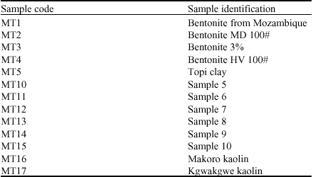
(USA). Samples were simply coded MT and numbered from 1 to 17 as indicated
in Table 1.
Analytical techniques: Granulometric analyzes which include PS,
PSD, modal diameter and SSA measurements of samples of clayey materials
were carried out employing both a mechanical shaker and a 1993 model Shimadzu
SA-CP4 Particle Size Analyzer (PSA). The bentonite and kaolin samples
were granulometrically characterized based on the principle of Stokes
law of sedimentation of individual spherical particles falling freely
at a steady velocity under the influence of gravity, resisted only by
the viscous drag of the medium (Gaspe et al., 1994), expressed
as:
Where:
V = Rate of settling of particles (cm sec
-1)
r = Radius of particles (cm)
d
p = Density of liquid medium (g cm
-3)
d
w = Density of water (g cm
-3)
η = Poise (g cm
-1 sec)
g = Acceleration due to gravity (981 cm sec
-2)
The mechanical/electrical shaker was set at 60 strokes per minute (spm)
for effective shaking and the nest of sieves consisted of the following
particle size ranges in μm: 180, 150, 125, 106 and 53. The < 53
μm size fraction of clay samples were analyzed using the 1993 model
Shimadzu SA-CP4 automatic Particle Size Analyzer (PSA). The analyzer was
set at 240 revolutions per minute (rpm) for effective segregation of particles.
The SSA and PS were automatically measured by the PSA.
RESULTS
Particle size (PS) and particle size distribution (PSD): The
textural classification utilized in this study is as follows: <= 2 μm
is clay, > 2 μm <= 50 μm is silt and > 50 μm <= 100
μm is sand (Jackson, 1956; Tan, 1998). A summary of the textural
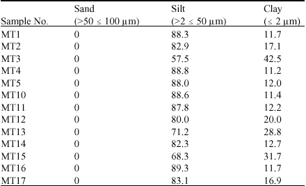
classification of the samples is given in Table 2. The
results revealed that all samples had particles with Euhedral Spherical
Diameter (ESD), which were <= 50 μm. 0 wt. % of particles of sample
MT1 were texturally classified as sand, 88.3 wt. % were silt and 11.7
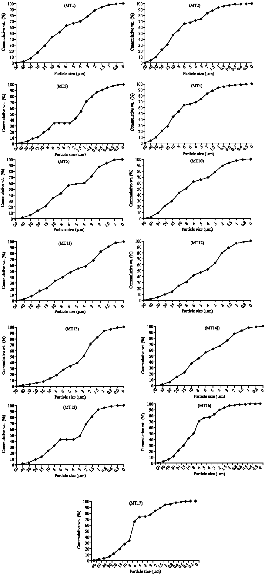
wt. % were clay (Table 2). The sample consisted of 43.5
wt. % being <= 10 μm and its cumulative frequency distribution curve
is given in Fig. 1. Sample MT2 constituted texturally
of 0 wt. % sand, 82.9 wt. % silt and 17.1 wt. % clay (Table
2). The sample consisted of 46.3 wt. % of particles being <= 10 μm
in which 17.1 wt. % is <= 2 μm and its cumulative frequency distribution
curve is reported in Fig. 1.
Sample MT3 consisted of 0 wt. % sand, 57.5 wt. % silt and 42.5 wt. %
clay. Approximately 71.2 wt. % of the sample consisted of particles being
<= 10 μm in which 42.5 wt. % was <= 2 μm and its cumulative
frequency distribution curve is reported in Fig. 1. Sample
MT4 comprised of 0 wt. % of particles being classified as sand, 88.8 wt.
% silt and 11.2 wt. % clay (Table 2). The cumulative
frequency curve is reported in Fig. 1. The cumulative
frequency distribution curve of sample MT5 is given in Fig.
1. From Table 2, sample MT5 was texturally 0 wt.
% sand, 88.0 wt. % silt and 12 wt. % clay. Sample MT10 consisted texturally
of 0 wt. % sand, 88.6 wt. % silt and 11.4 wt. % clay (Table
2) and its cumulative frequency distribution curve of the particles
are depicted in Fig. 1. The cumulative frequency distribution
curve of sample MT11 is plotted in Fig. 1. Sample MT11
constituted of 0 wt. % sand, 87.8 wt. % silt and 17.2 wt. % clay.
Sample MT12 consisted of 0 wt. % sand, 80 wt. % silt and 20 wt. % clay
(Table 2). Approximately 75.7 wt. % of particles contained
in sample MT12 were <= 10 μm and the cumulative frequency distribution
curve is represented in Fig. 1. Sample MT13 was texturally
composed of 0 wt. % sand, 71.2 wt. % silt and 28.8 wt. % clay. The sample
comprised 87.7 wt. % of particles being <= 10 μm and its cumulative
frequency distribution curve is plotted as Fig. 1. Sample
MT14 consisted of 0 wt. % sand, 82.3 wt. % silt and 12.7 wt. % clay as
indicated in Table 2.
Table 1: |
Sources, identification and codes of clay samples |
 |
Table 2: |
Particle weight percent in relation to textural classification
of samples |
 |
Approximately 61.9 wt. % of particles in sample MT14 were <= 10 μm
and its cumulative frequency distribution curve plotted as Fig.
1.
From the particle size distribution curve shown in Fig.
1, sample MT15 comprised of 80 wt. % of particles being <= 10 μm,
of which 12.7 wt. % were texturally classified as clay size particles.
The PSD curve for sample MT16 is given in Fig. 1. Sample
MT16 was constituted of 0 wt. % of particles texturally classified as
sand, 89.3 wt. % silt and 11.7 wt. % clay. Approximately 41.9 wt. % of
the particles in sample MT16 were <= 10 μm, in which 11.7 wt. % of
them were <= 2 μm. From Fig. 1 and Table
2, 83.1 wt. % of particles contained in sample MT17 were texturally
classified as sand and 16.9 wt. % as clay.
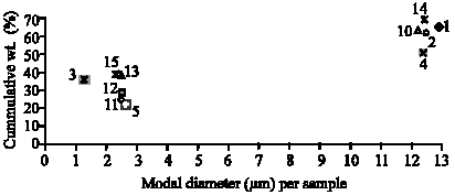
Modal diameters of particles: The modal diameters of bulk clay
samples were between 1 and 13 μm. From the results obtained for PSD,
the samples were grouped into two classes based on their modal diameters
as observed in Fig. 2. The first class of samples were
those with high modal diameters and high cumulative wt. % at which the
modal diameters occurred. Samples MT1, MT2, MT4, MT10 and MT14 had their
modal diameters occurring between 11 and 13 μm and with corresponding
cumulative wt. % between 45 and 70 wt. %.
|
Fig. 1: |
Cumulative frequency distribution curve of samples of
clayey materials |
The second class of samples consisted of those with low modal diameters
and low cumulative wt. % and these were MT3, MT5, MT11, MT12, MT13 and
MT15. The modal diameters of these samples occurred between 1 and
3 μm and they had corresponding cumulative wt. % within the range
of 20 and 40 wt. %. No samples had its modal diameter within the range
of 4 and 10 μm.
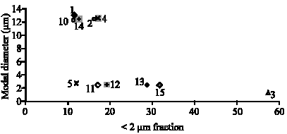
Two classes of samples as shown in Fig. 3 were distinguished
based on the modal diameters of samples in relation to the cumulative
wt. % of the <= 2 μm. The first class of samples were those with
high modal diameters. Samples MT1, MT2, MT4, MT10 and MT14 had their modal
diameters occurring between 12 and 14 μm and with corresponding
cumulative wt. % of the <= 2 μm fraction within the rage of 10 and
20 wt. %.
|
Fig. 2: |
Comparison of modal diameter and cumulative
wt. % of bulk clay samples |
|
Fig. 3: |
Comparison of modal diameter and cumulative
wt. % of the <= 2 μm fraction of clay samples |
|
Fig. 4: |
Specific surface area of samples of clayey materials |
The second class of samples had low modal diameters compared to the first
class. The samples, which were MT5, MT11, MT12, MT13 and MT15, had their
modal diameters occurring between <=1 and 2.5 μm and they had corresponding
cumulative wt. % within the range of 10 and 33 wt. %. Sample MT3 was noted
to have both the lowest modal diameter (1.4 μm) and the highest cumulative
wt. % of the <= 2 μm fraction (58 wt. %).
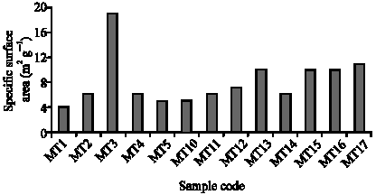
Specific surface area of particles: The Specific Surface Area
(SSA) of samples obtained ranged from 4 to 19 m2 g-1
and the results are given in Fig. 4. Based on values
obtained for SSAs of samples analyzed, they could be subdivided into three
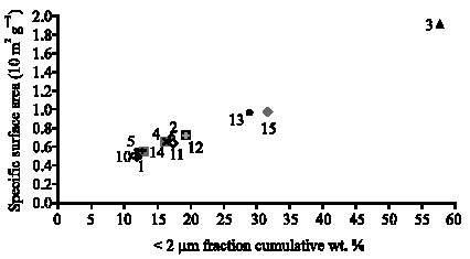
classes. Samples with low specific surface areas also had low cumulative
wt. % of the <= 2 μm fraction as demonstrated in Fig.
5. The first class of samples were MT13 and MT15, which
had SSAs of 10 m2 g-1 and their cumulative wt. %
of the <= 2 μm fraction were 35 and 40 μm, respectively. The
second class were samples MT1, MT5, MT10 and MT14 having SSAs between
4 and 6 m2 g-1. The third class were samples MT2,
MT4, MT11 and MT12 and they had SSAs between 6 and 8 m2 g-1.
The SSA of sample MT10 was 10 m2 g-1 and sample
MT17 had a SSA of 11 m2 g-1. The SSA for sample
MT3 was 19 m2 g-1 and its cumulative wt. % of the
<= 2 μm fraction was 59 μm.
|
Fig. 5: |
Comparison of specific surface area and cumulative wt.
% of the <= 2 μm fraction of samples of the clayey materials |
DISCUSSION
The PSD of argillaceous sediments is an important property, affecting
the ceramic strength of any clayey material (Murray, 1986). Jackson (1956)
divided the grain particles of sediments into three main classes based
on sizes: sand (50-1000 μm), silt (> 2-50 μm) and clay (<
2 μm) (Tan, 1998). This division of particles is indicative of the
texture of the clayey material. Of the studied samples, based on the textural
classification by Jackson (1956), none had a sand component as most of
the particles ranged from 0.02 to 50 μm (Table 2,
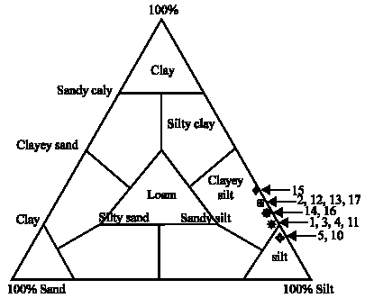
Fig. 1). The samples analyzed depicted the clays to be
classified as clayey silts based on the ternary diagram represented as
Fig. 6, of PSD devised by Shepard (1954) and applied
by Strazzera et al. (1997) and Dondi et al. (1992), to Tertiary
clays from southern Sardina, Italy that are widely used in ceramic industry.
The particles of clayey material suitable for ceramic applications are
classified as silty clay, clayey silt (Dondi et al., 1992; Parras
et al., 1996), except for samples MT5 and MT10 as indicated in
Fig. 6, which had their texture consisting of silt. This
information is relevant to the degree of heat flow and water absorption
capacity of clayey material.
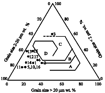
The studied clay samples were functionally distributed using the grain
size classification according to Winklers scheme as applied to clays
from southern Italy (Dondi et al., 1992). Figure 7
gives the allocation of the clays studied in their various fields of applications:
common bricks, vertically perforated bricks, roofing tiles and masonry
bricks and hollow products. Based on the classification of clayey materials
according to Winklers scheme, as reflected in Fig. 7,
samples MT5, MT10, MT11 and MT16 are suitable for the fabrication of common
bricks; samples MT1, T2 MT4, MT12, MT13, MT14, MT15 and MT17 could be
used for the making of vertically perforated bricks and sample MT3 may
have to be ameliorated to be utilized for any brick fabrication.
|
Fig. 6: |
Ternary diagram classification of
clay samples based on sand-silt-clay ratios (Note that the numbers
signify samples and are all preceded by MT) (Dondi et al.,
1992; Tan, 1998; Jackson, 1956) |
|
Fig. 7: |
Grain size classification of studied
clays according to Winklers scheme. Fields are characteristic for:
(A) common bricks, (B) vertically perforated bricks, (C) roofing
tiles and masonry bricks (D) hollow products. (Numbers are indicative
of sample numbers and are preceded by MT). (Dondi et al.,
1992; Tan, 1998; Jackson, 1956) |
Modal diameters of the samples analyzed were of two groups: 1-3 and 11-13 μm.
Clays used in ceramics have modal diameters between 1 and 5 μm (Murray,
1986). The first group of samples qualifies for ceramic usage. Whereby modal
diameters are high as in the second group of studied samples, the clays can
be mixed with different clayey material; in which case the composite claybody
will have reduced modal diameters, which can be accommodated in the ceramic
industry. ad2ad4**ad5
The SSA of any clayey material is a variable used in the determination
of clay suitability for ceramic applications. According to Kaolins (2000),
the SSA of most commercial clays used for ceramics is 10 m2
g-1. The studied samples had SSA values between 4 and 19 m2
g-1. The SSA of clay particles has a linear relationship
with the particle size. Clay particles are flat and are randomly oriented.
Particle size and orientation affect the clays drying shrinkage, which
has a consequence on the finished product (Ceramic Terminology, 2001).
Finer particles tend to increase the rate at which reactions occur in
the kiln/furnace (Bloodworth et al., 1993). Based on PS and PSD,
modal diameters of samples and their SSAs, all the clay samples analyzed
in this study were found to be suitable for ceramic applications.
CONCLUSION
The grain size of any clay definitely has a bearing on its viscosity,
color, abrasiveness and ease of dispersion (Murray, 1999). Although the
results obtained from granulometric analyses show that these clays are
suitable to be used in the ceramic industry, there are other controlling
factors such as the clay mineralogy and clay chemistry, which usually
influence the quality of the finished product. In this regard, a beneficiation
exercise may have to be carried out depending on the specific ceramic
application designated for the clay material to be utilized.