
S.S. Hosseini Yazdi
Faculty of Mechanical Engineering, University of Tehran, Tehran, Iran
M. Mousavi Mashadi
Faculty of Mechanical Engineering, University of Tehran, Tehran, Iran
Journal of Applied Sciences
Year: 2007 | Volume: 7 | Issue: 3 | Page No.: 392-396


ABSTRACT
Carbon nanotubes are used to store fuel to generate energy in fuel cell systems. In this regard, a nano-piping systems are needed to transfer and control the molecules of fuel flow, through the cell system. In this study a voltage actuated nano-valve system to control the molecule flow, has been presented which consists of a both ends fixed Single wall carbon nanotube (SWNT) and a ground plane. To show the function of presented nano-valve, both van der Waals between SWNT and the ground plane and electrostatic forces due to voltage inducement are considered. Induced voltage causes SWNT to deflect. When kink phenomenon happens due to SWNT deflection, the molecules path will be closed. In comparison to previous presented nano-valves, this nano-valve has better controlling features and faster and easier actuation.
PDF Abstract XML References Citation
How to cite this article
S.S. Hosseini Yazdi and M. Mousavi Mashadi, 2007. A Voltage Actuated Nano-valve System Design. Journal of Applied Sciences, 7: 392-396.
DOI: 10.3923/jas.2007.392.396
URL: https://scialert.net/abstract/?doi=jas.2007.392.396
DOI: 10.3923/jas.2007.392.396
URL: https://scialert.net/abstract/?doi=jas.2007.392.396
INTRODUCTION
Carbon nanotubes, attracted considerable studies on their characteristics and functionalities. Their novel mechanical and electrical properties, have nominated them for several applications. One of their applications is storing and transferring molecules as nano-tanks and nano-piping, systems, especially for power generation. Qian et al. (2002) showed that Molecular dynamic simulations indicates which fuel molecules like Hydrogen or Methane are attracted into the SWNTs and due to attraction forces, the molecules are accelerated, therefore SWNTs are known as super high ways to transfer such these molecules. For controlling the flow, nano-valve systems should be used. The presented nano valve systems by Grujicic et al. (2005) consists of a one end fixed SWNT and a cantilever silicon beam. Such this beam has one face covered (functionalized) with self assembled or chemically bonded molecules of various type and can deflect by themselves due to differences in the surface stress between the functionalized and non-functionalized faces. It is able to actuate only in solution environment. By altering environment PH, the cantilever silicon beam which is functionalized with a covalently bonded monolayer of acrylic acid molecules, deflects to cause SWNT deflection and kink in order to block molecules path. In such a system, exact control of environment PH is very hard and needs certain solutions, the process is slow and waste material are produced during opening and closing of nano-valve.
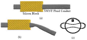 | |
| Fig. 1: | (a) One end of nano-vale, fixed in silicon block, On position. (b) Off position of nano-valve due to voltage inducement. (c) Cross section of nanotube for On and Off positions of nano-valve |
The objective of this study is to introduce a nano-valve system, which is made of a SWNT. In this system, applied voltage causes deflection in SWNT. When SWNT becomes unstable, buckles and collapses on a ground plane. In this way, molecules' path will be blocked. The advantages of presented system are: the system is not confined to any certain environment, its control and actuation is very easy and uses little energy and does not produce any waste, also the actuation is very fast. Therefore many applications can be found for such this system (Fig. 1).
NANO-VALVE MODELING
In order to simulate nano-valve, SWNT instabilities and electrostatic, van der Waals and elastic domains should be considered.
PULL-IN PHENOMENON
Proposed nano-valve is composed of a fixed ends SWNT and a fixed graphite ground plane. Dequesnes et al. (2002a,b) showed in the case of applying a voltage on system, induced electrostatic charges, cause electrostatic forces, which are dependent to gap between SWNT and graphite plate. van der Waals interactions between them exist too. For an applied voltage, the equilibrium position is defined by balance of applied forces. Force amount changes are related to SWNT deflection; therefore, a self consistent analysis should be used to find equilibrium position. As the applied voltage reaches to a certain point, the SWNT becomes unstable and collapses on the graphite plane. This phenomenon is called Pull-in and relative voltage, Pull-in voltage. Wang and Varadan (2005) showed this phenomenon is because of SWNTs kink instability at bending. This phenomenon has been observed by high resolution transmission electron microscopes too. The proposed flexural stiffness for a nanotube, using beam theory is employed to describe kink phenomenon. Under pure bending, the strain at the compressive side, according to Euler-Bernoulli beam theory is:
| (1) |
Where κ is the beam curvature, dNT nanotube diameter and hNT nanotube effective thickness. It is assumed that kink will occur, when the strain energy at the inner wall of the compressive side reaches the critical value. Since stress and strain follow a linear distribution in radial direction, it is reasonable to assume that kink instability happens when compressive strain reaches twice the critical in-plane strain under uniformly distributed compression. The kink happens at:
| (2) |
Where L is nanotube length.
VAN DER WAALS INTERACTIONS
To model these interactions, Lennard-Jones potential is used, which is described as:
| (3) |
Where rij is distance between two atoms (I, j), C6 and C12 are attractive and repulsive constants. For C-C interaction, the attractive and repulsive constant are; C6 = 24.32x10-79 j.m6 and C12 = 3.872x10-136 j.m12.
Dequesnes et al. (2002a,b) and (2004) showed that the ground plane is modeled as N layer graphite sheets and a graphite bulk beyond. Such a representation to model the ground plane is justified because the integration of a graphite sheet with SWNT accounts for the atomic structure of the original system and produces a result very close to the double summation of lennard-Jones potential. If the ground plane is located far away from nanotube, the graphite sheets can be modeled as graphite bulk. The interaction force between an atom on SWNT and graphite plane can be calculated by differentiating Eq. 1 with respect to rij and integrating over ground plane:
| (4) |
Where ra is the distance between the atom on SWNT and graphite sheet and σ = 38 nm-2 is graphite surface density. The expression for the force on an atom on SWNT due to its interaction with graphite bulk is given by:
| (5) |
and ρ = 1.14x1029 m-3 is graphite volume density. By integrating forces over SWNT ring, force per unit length, characterizing the van der Waals interaction can be obtained:
 | (6) |
| (7) |
that q is force per unit length, d = 0.34 nm graphite interlayer spacing, R is the nanotube radius and rinit is distance between atom and top of the ground plane (Fig. 2).
The van der Waals force per unite length is:
| (8) |
 | |
| Fig. 2: | van der Waals interaction of a SWCNT over graphite sheets |
ELECTROSTATIC INTERACTIONS
Dequesnes et al. (2004) also showed that electrostatic interactions are calculated, using classical capacitance model. The capacitance per unite length for the cylindrical beam over a conductive ground plane is given by:
 | (9) |
Where ε0 is the vacuum permittivity. The electrostatic force per unit length is:
 | (10) |
and V is applied voltage.
GOVERNING EQUATION
The electromechanical behavior of SWNT is approximated by a continuum beam equation:
| (11) |
The Eq. 11 is highly nonlinear, which implies that there is no analytical solution, therefore, solution would obtain by numerical method.
 | |
| Fig. 3: | van der Waals interaction variation due to number of layers |
In current study, for SWNT; dNT = 1.19 nm, hNT = 0.34 nm, L = 20.32 nm, rinit = 5.22 nm and Eeffective = 1.03 Tpa are considered as geometry features and lump solution model has been employed. Lump model considers uniform electrostatic load distribution on SWNT before Pull-in phenomenon. Therefore this method shows the down bond of the Pull-in voltage.
At first stage, just, van der Waals force is calculated to find initial deflection. Where qgraphite increases less than 1% is assigned as the number of graphite sheets (N). It was found that when N = 20, the increase of qgraphite becomes neglect able (less than 1%) (Fig. 3).
Then, by using a repetitive approach, deflection and slope of SWNT due to voltage inducing is calculated. The criterion to stop the iteration is qele increase becomes less than 1%. When r gets equal to 0.34 nm, it means that the nanotube has reached to graphite plane. Due to assumed nanotube geometry features, the critical slope has been found 11.59°. When the induced voltage reaches to pull-in amount, the SWNT kinks and collapses on the ground plane which block the flow path (Fig. 4-7).
In Finite Element Analysis (FEA) software (ANSYS 9.0), SWCNT has been modeled as a space frame, which their mechanical properties had been obtained by authors, based of carbon lattice force constants which have been used by Tserpes and Papanikos (2005), Odegard et al. (2003), Leamy (2005) and Ruoff et al. (2003). The space frame mechanical properties are considered as: dframe = 0.1448 nm and Eframe = 6 Tpa. In the carbon lattice, there are bonding and non bonding interactions. The Modified Morse Potential shows the bonding interactions and Lennard-Jonnes Potential can be employed to show non bonding interactions. Considering theses interactions separately lead us to have a space frame with twelve elements (Fig. 8). Applying such this model for SWNT is hard and time taking. To reduce the number of elements and calculations to half, effective space frame elements developed which forms SWNT by hexagonal carbon lattice and considers bonding and non bonding interactions together.
 | |
| Fig. 4: | SWCNT slope due to voltage inducement |
 | |
| Fig. 5: | Applied electrostatic force on SWNT due to voltage inducement |
 | |
| Fig. 6: | SWNT mid point deflection due to voltage inducement (Analytic model) |
Using qvdw + qele, applied force on each SWNT atom has been calculated. The space frame model shows the pull-in phenomenon too. When pull-in happens, the performed buckling analysis indicates kinks near both ends, which blocks the path of moving molecules (Fig. 9 and 10).
 | |
| Fig. 7: | Nanotube deflection due to voltage inducement |
 | |
| Fig. 8: | Space frame model with separated elements representing bonding and non bonding interactions |
 | |
| Fig. 9: | SWNT mid point deflection due to voltage inducement (FEA model) |
In this study a good agreement between FEA and analytic effective continuum results has been seen.
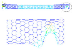 | |
| Fig. 10: | SWNT kink phenomenon near on end, Off position of nano-valve (FEA model) |
CONCLUSIONS
In current study, presented nano-valve system made of SWNTs do not needs solution environment. Thus, it is not confined to any restricted environment. Its actuation is much faster and easier to control because, voltage inducement is much faster and easier than environment PH control. Even it is possible to compare its switching speed between On and Off positions with high speed transistors. By the way, it has very low energy consumption and uses no solvent therefore no waste material is produced. Two analytic continuum and space frame model through FEA method to demonstrate the nano-valve mechanism were considered and their results were in agreement with each other. When applied voltage reaches to a certain amount which Pull-in happens, the nanotube kink near both ends blocks the path.
REFERENCES
- Dequesnes, M., S.V. Rotkin and N.R. Aluru, 2002. Calculation of pull-in voltage for carbon nanotube-based nanoelectromechanical switches. Nanotechnology, 13: 120-131.
Direct Link - Dequesnes, M., S.V. Rotkin and N.R. Aluru, 2002. Parameterization of continuum theories for single wall carbon nanotube switches by molecular dynamics simulations. J. Comp. Elect., 1: 313-316.
Direct Link - Dequesnes, M., Z. Tang and N.R. Aluru, 2004. Static and dynamic analysis of carbon nanotube based switches. J. Eng. Mater., 126: 230-237.
Direct Link - Grujicic, M., G. Cao, B. Pandurangan and W.N. Roy, 2005. Finite element analysis-based design of a fluid-flow control valve. Mater. Sci. Eng. B, Solid-State Mater. Adv. Technol., 117: 53-61.
Direct Link - Qian, D., G.J. Wagner, W.K. Liu, M.F. Yu and R.S. Ruoff, 2002. Mechanics of carbon nanotubes. Applied Mech. Rev., 55: 495-533.
Direct Link - Ruoff, R.S., D. Qian and W.K. Liu, 2003. Mechanical properties of carbon nanotubes: Theoretical predictions and experimental measurements. Comptes Rendus Physique, 4: 993-1008.
Direct Link - Tserpes, K.I. and P. Papanikos, 2005. Finite element modeling of single walled carbon nanotubes. Comp. Part B: Eng., 36: 468-477.
Direct Link - Wang, Q. and V.K. Varadan, 2005. Stability analysis of carbon nanotube via continuum models. Smart Mater. Struct., 14: 281-286.
Direct Link