
Tzong-Mou Wu
Department of Mechanical Engineermg, Far East College, Tainan 744, Taiwan
Journal of Applied Sciences
Year: 2005 | Volume: 5 | Issue: 4 | Page No.: 724-728


ABSTRACT
The automation design program of planar four-link mechanisms, including four-bar and slider-crank mechanisms, were presented. This program was developed on popular windows platform by Microsoft visual basic language. The program can manage maximum analytical precision points’ synthesis problems of planar four-link mechanisms. We just input necessary desired specs, the link lengths and mechanism profile will quickly be determined by this program. Moreover, the animation simulation can also be performed in this program. Some examples were given in this study for illustration purpose.
PDF Abstract XML References Citation
How to cite this article
Tzong-Mou Wu, 2005. Non-linear Solution of Function Generation of Planar Four-link Mechanisms by Homotopy Continuation Method. Journal of Applied Sciences, 5: 724-728.
DOI: 10.3923/jas.2005.724.728
URL: https://scialert.net/abstract/?doi=jas.2005.724.728
DOI: 10.3923/jas.2005.724.728
URL: https://scialert.net/abstract/?doi=jas.2005.724.728
INTRODUCTION
Tao[1] developed a serial of graphical synthesis methods in 1964’s. However, as we known, the graphical methods are not exact solutions. Also, the methods have some disadvantages such as the limitation of precision points and the inaccuracy of drawing and so on. The loop-closure equation had carried out by Freudenstein[2]. The Freudenstein’s equation provided the ability to get exact solutions. Nevertheless, we still must use calculator, even computer, to help us to accomplish higher analytical precision points by Freudenstein’s equation. Freudenstein’s equation provided maximum 3 linear exact solutions and maximum 5 non-linear analytical solutions. There are different works that has been devoted to the courses of mechanism design until today[3-6].
In the process of solving mechanism design problems, some troublesome simultaneous equations would be generated, especially the simultaneous non-linear equations. Up to the present, we have already many different methods can deal with the simultaneous non-linear equations[7]. The initial guesses in these numerical methods are a big trouble. Good initial guesses can faster converge to the answers. Reversely, bad initial guesses perhaps imply divergence. It’s a well-known common sense.
Homotopy continuation method was known as early as in the 1930’s. This method was used by kinematician in the 1960’s in the U.S. for solving mechanism synthesis problems. The latest development was done by Morgan[8] at GM. We also have three literatures by Morgan[9,10], Garcia[11] and Allgower[12]. Morgan’s issues are better readable than others. Continuation method gives a set of certain answers and some simple iteration process to obtain our solutions more exactly. Wu[13,14] presented some techniques for combining Newton’s, ancient Chinese algorithm and homotopy methods to avoid divergence on solving non-linear equation. Moreover, Wu[15] explored all the linear and non-linear solutions of the kinematics design problems as well as Wu[16] applied the homotopy continuation method to search all the roots of inverse kinematics problem of robot. This study attempt to use Freudenstein’s equation and homotopy continuation method to solve the maximum analytical precision points’ synthesis problems of planar four-link mechanisms. The program is developed on current popular windows platform by Microsoft visual basic language. Further, the program is provided in this study. (http://home.kimo.com.tw/tm.wu/Programs/Programs.htm):
Freudenstein’s equation and homotopy continuation method: Consider Fig. 1, the planar four-bar linkage mechanism has the following Freudenstein’s equation
| (1) |
Where:
| (2) |
Observing Eq. 1 and 2, the givens are (φi, Ψi) and unknowns are (Z1, Z2, Z3, Z4). Since Z1 is a scale, it can be chosen arbitrarily. The real unknowns therefore become (Z2, Z3, Z4). Hence we only have three equations to solve maximum three unknowns linearly by Cramer’s rule or Gauss elimination method, etc.
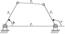 | |
| Fig. 1: | The planar four-bar linkage mechanism |
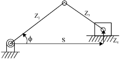 | |
| Fig. 2: | The planar slider-crank mechanism |
However, according to the Chebyshev spacing in the actual synthesis problems, we have two free variables can be assigned, i.e. (φ0, Ψ0), which are the initial position of our desired input and output design intervals. In other words, we total have five unknowns (Z2, Z3, Z4, φ0, Ψ0) to be determined. It will yield Eq. 1 to be
| (3) |
Theoretically, Eq. 3 can satisfy infinite positions (φi, Ψi) just by the five variables (Z2, Z3, Z4, φ0, Ψ0). We can use so-called overlay method to synthesize this kind of mechanism. In fact, the successful probability is very lower. With the natural constraints of planar four-link mechanisms, we only can get 2 or 3 precision points for linear solutions and 4 or 5 precision points for nonlinear solutions by Freudenstein’s equation. To ensure the existence of solutions, the n unknowns must correspond to n equations. This is Newton’s fundamental theorem of algebra. So we can solve Eq. 3 analytically up to maximum 5 input-output position relationships, i.e. 5 precision points. But, the five unknown variables in Eq. 3 are coupled each other. We have to apply numerical technique to solve them. The Newton-Raphson is a famous method. The defect is acquirement of good initial guesses. With the aid of homotopy continuation approach, we will more correct and quicker to obtain the results.
Firstly, we rewrite Eq. 3 as function f(Z2, Z3, Z4, φ0, Ψ0), then we assume a new controllable/given function g(Z2, Z3, Z4, φ0, Ψ0). The homotopy continuation function therefore is defined as:
| (4) |
Where:
 | (5) |
The last two terms -2cos(φ00)-2 of function g mean the correction dependent on the controllable initial guesses (K1, K2, K3, Ψ0) = (1, 1, 1, 0) for 4 precision points. As well as (K1, K2, K3, φ0, Ψ0) = (1, 1, 1, φ00, 0) = (1, 1, 1, 0, 0) for 5 precision points.
What we have to do is change the homotopy parameter t from 0 to 1 to get the answer of f = 0. By the test, the iteration times do not need very large. We just only need to iterate 100 times to yield the converge results. Of course, the iteration procedure of Newton-Raphson method is still necessary. In many situations, the convergence speed of Newton-Raphson combined with homotopy is faster than only using the Newton-Raphson method.
Secondly, from Fig. 2, the Freudenstein’s equation of planar slider-crank mechanism is:
| (6) |
Where:
| (7) |
Similarly, the homotopy continuation function for the planar slider-crank mechanism is defined as:
| (8) |
Where:
 | (9) |
EXAMPLES
Example 1: Synthesis of planar four-bar mechanism with 2 precision points: If we would like to synthesize 2 precision points from Eq. 1, one free choice should be given because of we have 2 equations and 3 unknowns (Z2, Z3, Z4) or (K1, K2, K3). One variable of Z2, Z3 or Z4 will be assigned to determine following simultaneous linear equations
| (10) |
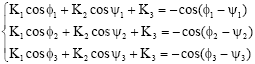
We design the free choice as Z2 in this study. Of course, Z1 also is the free choice in all cases of planar four-bar linkage mechanisms. We give the input-output data, (φ1, Ψ1) and (φ2, Ψ2), in this example as enter the values and free choices Z1 = 5.2, Z2 = 0.8 shown in Fig. 3. The results are the same with Tao[1] contribution.
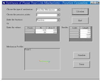
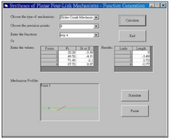
Example 2: Synthesis of planar slider-crank mechanism with 2 precision points: In general, planar slider-crank mechanism with 2 precision points means crank and piston system. Similarly, if we desire to synthesize this kind of mechanism. Consider Eq. 6, we can choose the free variable from Z2 (crank length) or Z4 (offset from fixed pivot to slider) to determine simultaneous linear Eq. 11. This study provides these two choices. In this example, we let offset Z4 =-2 to compare with Tao[1] literature.
| (11) |
The answers are also the same with Tao[1]. Note that, in Fig. 4, Z1 denotes Si displacement in the planar slider-crank mechanism, drawn in Fig. 2. We already give them values in “Si or S” column of Fig. 4. So we do not need to assign its data again. On the other hand, the scale in this mechanism should be the real dimension of the slider.
Example 3: Synthesis of planar four-bar mechanism with 3 precision points: Three precision points are the limitation of the planar four-link mechanism syntheses, including four-bar and slider-crank mechanisms, with simultaneous linear equations. We do not need to assign redundant free variable except for the fixed link Z1 for four-bar linkage. The simultaneous linear equations in this example are
 | (12) |
Now, we run this example as the type of enter the function, shown in Fig. 5. We supply the design information as:
| (13) |
 | |
| Fig. 3: | Synthesis of planar four-bar linkage mechanism with 2 precision points |
 | |
| Fig. 4: | Synthesis of planar slider-crank mechanism with 2 precision points |
 | |
| Fig. 5: | Synthesis of planar four-bar linkage mechanism with 3 precision points |
 | |
| Fig. 6: | Synthesis of planar slider-crank mechanism with 4 precision points |
 | |
| Fig. 7: | Synthesis of planar four-bar linkage mechanism with 5 precision points |
Where, φ0, Ψ0 and Z1 are arbitrary. Specifically, φ0 and Ψ0 are arbitrary for linear solutions of Eq. 12 by means of using Chebyshev spacing method to yield (φ1, Ψ1), (φ2, Ψ2) and (φ3, Ψ3). We can also change any value (φi, Ψi) by “Click” and input data in the “Values Grid” in Fig. 5 to meet special location requirement such as positioning machine.
The computation results of links length, shown in Fig. 5, are checked by Sandor[5]. They are the same.
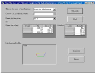
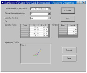
Example 4: Synthesis of planar slider-crank mechanism with 4 precision points: Exceed 4 precision points, Eq. 1 and 6 will become non-linear. This is discussed in previous section. We especially apply the homotopy continuation method to handle this problem. Also, we define two homotopy functions (4) and (8), respectively in this paper to solve the simultaneous non-linear equations.
We give the following design specs to run this example. The answers are shown in Fig. 6. The automation program takes us just 0.47 sec in merely AMD-K6/2-500 CPU.
| (14) |
Where, we still have one free parameter φ0 to be chosen arbitrarily in all problems of 4 precision points syntheses.
Example 5: Synthesis of planar four-bar mechanism with 5 precision points: By the similar manner, we provide a set of design data as following to synthesize the planar four-bar linkage mechanism with 5 precision points
| (15) |
We can also obtain these design data from Hartenberg’s book[4]. Owing to the computation of this program, we find the inaugural Chebyshev’s data x1 to x5 are puzzle in Hartenberg’s book. They seem wrong.
The final results of this example are shown in Fig. 7. The program takes us just only about 0.64 sec to run this example. It presents that the homotopy continuation method has high efficiency in solving simultaneous non-linear equations.
CONCLUSIONS
All mechanism design problems should solve simultaneous equations except for graphical methods. However, the graphical methods can not obtain the better accurate results. We must use analytical methods to determine the exact solutions. Whatever we solve what kinds of simultaneous equations and no matter how many precision points are assigned, we always have two types of simultaneous equations. They are linear and non-linear. This paper applies Gauss elimination and Homotopy continuation methods to solve simultaneous linear and non-linear equations, respectively.
In analytical solving the planar four-bar and slider-crank mechanisms, we have 2 to 5 precision points can be assigned. The giving of 2 or 3 precision points can generate simultaneous linear equations. However, 4 or 5 precision points will generate simultaneous non-linear equations. The solutions for these two types are not difficult for this program. Over 5 precision points, we should use graphical method such as overlay method. It is not a closed form method. It is a trial and error technique and not guarantees the solutions. As we known, more free variables mean more answers for our problems. Reversely, we can equate less free choices to lesser results for the design problems. So it is not easy for us to certainly say what kind of design problems is nice. May be, we should decide them by the real needs.
This study develops a PC’s program on windows platform by Microsoft visual basic language to solve the design problems of planar four-bar and slider-crank mechanisms. Some programming techniques and debug measures are applied and included in the program. Furthermore, the animation simulation artifice is also been combined in this program. From this program, we can quickly and exactly obtain our desired requirements and view the animation simulation real-time. It is hoped that the study presented here will contribute towards progress in the kinematics syntheses of mechanisms and provide some programming approaches for the scientists or engineers.
REFERENCES
- Wu, T.M., 2005. A study of convergence on the newton-homotopy continuation method. Applied Math. Comput., 168: 1169-1174.
Direct Link - Wu, T.M., 2005. A modified formula of ancient Chinese algorithm by the homotopy continuation technique. Applied Math. Comput., 165: 31-35.
Direct Link - Wu, T.M., 2005. Searching all the roots of inverse kinematics problem of robot by homotopy continuation method. J. Applied Sci., 5: 666-673.
CrossRefDirect Link