
G. Marahleh
Department of Materials and Metallurgical Engineermg,
Faculty of Engineering, Al-Balqa Applied University, Al-Salt, Jordan
Journal of Applied Sciences
Year: 2005 | Volume: 5 | Issue: 6 | Page No.: 1004-1011


ABSTRACT
Fatigue properties of spheroidal graphite cast iron (SGI) and compacted graphite cast Iron (CGI) were studied in this research. Specimens in form of strips (94x9x3.8 mm) were subjected to alternating bending fatigue tests. S-N curves and fatigue limits for both materials were determined. From the crack growth rate vs. average crack length curves, two behaviors were observed, namely short crack growth rate and long crack growth rate. Mathematical models were suggested describing both types of cracks, thus enabling the calculation of fatigue life of SGI and CGI. From da/dN versus stress intensity variation experiments, the Paris equation da/dN = C (ΔK)P was derived. The smaller the value of p the better is the crack growth resistance of the material. For SGI, p = 1.1855 and for CGI, p = 1.2434 indicating inferior crack growth resistance of the CGI.
PDF Abstract XML References Citation
How to cite this article
G. Marahleh, 2005. Fatigue Crack Propagation in SGI and CGI. Journal of Applied Sciences, 5: 1004-1011.
DOI: 10.3923/jas.2005.1004.1011
URL: https://scialert.net/abstract/?doi=jas.2005.1004.1011
DOI: 10.3923/jas.2005.1004.1011
URL: https://scialert.net/abstract/?doi=jas.2005.1004.1011
INTRODUCTION
Fatigue problems are the most important problem in industrial applications and machinery parts. Few studies were carried out on fatigue properties of both SGI and CGI. These two materials are important for applications where high fatigue life and wear resistance are required, as in crankshafts and brake system of vehicles[1]. The increased firing pressures in direct injection diesel engine increased mechanical loads on the main bearing region of the cylinder block, potentially resulting in premature fatigue failures. The trend toward higher peak firing pressures have prompted engine designers to seek stronger materials in order to meet their durability targets without increasing the size or weight of their engines[2]. The morphology of the graphite in cast iron whether it is flake, compacted or spheroidal determines the mechanical and physical properties of cast iron[3]. The graphite particles can act as internal notches, thus causing stress concentration, as in gray cast iron, this means, it is considered to be hardly influenced by external notches[4]. The CGIs have a useful combination of properties which have made them an attractive choice for a number of applications and they have become an important addition to the range of engineering cast irons. A useful combination of relatively high strength and good thermal conductivity has proved to be of advantage in a number of applications where the casting requires withstanding thermal cycling. The combination of greater cracking resistance compared to conventional flake graphite irons and better resistance to distortion compared with nodular irons has resulted generally in improved ingot mould lives[5]. In order to better understanding of fatigue properties, fatigue strength and Fatigue Crack Propagation (FCP) further studies are necessary particularly on SGI and CGI[5,6].
Fatigue properties in CGI are influenced by the matrix structure, the percentage of spheroidal graphite and the presence of mechanical notches. Slightly higher percentages of spheroidal graphite increase the fatigue limit (σw) as well as the endurance ratio (limit). The presence of a large amount of pearlite in the matrix structure also increases the σw. The effect of matrix structure on σw is less pronounced and the σw is significantly lower in the presence of notches[7]. The good fatigue performance of CGI stems directly from the compacted graphite morphology. The rounded edges of the graphite particles do not contribute to crack initiation and actually serve as crack arresters once cracks are formed. The complex coral-like morphology and irregular surfaces of the graphite particles thereafter result in good adhesion and thus present a more tortuous crack propagation path relative to the smooth flake surfaces in gray iron. These same morphological characteristics result in a two-to-four-fold increase in the thermal fatigue resistance of CGI relative to gray iron[8].
The effect of different temperatures, the ambient (25°C) and intermediate (150°C) were studied on the crack growth rate da/dN vs stress-intensity variation (ΔK) in CGI with different vermicularity and matrix structures[3]. For the same matrix structure, CGI with higher vermicularity yielded lower fracture toughness values and for the same vermicularity, the pearlitic matrix exhibited higher fracture toughness values than those of ferritic matrix. At elevated temperature the P value in Paris equation was lower, indicating that the crack growth resistance was improved.
In studies[9,10], it was shown that σw of SGI and CGI is higher in pearlitic base cast irons than those of ferritic irrespective of the shape of dispersed graphite particles. SGI showed higher σw compared with those of CGI.
MATERIALS AND METHODS
The fatigue tests were carried out on SGI (3.44% C, 2.68% Si, 0.16% Mn, 0.02% P, 0.015% S) and CGI (3.15% C, 1.84% Si, 0.42% Mn, 0.02% P, 0.014% S) using an alternating bending fatigue machine. The specimens were prepared in form of strips with dimensions (94 mm long, 9 mm wide, 3.8 mm thickness). They were prepared from cast Y-blocks. The matrix structure of SGI was 80% ferrite and 20% pearlite with an average graphite nodule count of 188 mm-2 and that of CGI was 25% ferrite and 75% pearlite.
The mechanical properties of SGI are (σy = 380 MPa, σu = 452 Mpa, HB = 179, elongation = 12%) and those of CGI are (σy = 299 MPa, σu = 368 MPa, HB = 202, elongation = 1.5%). The maximum surface roughness of the specimens is Rmax= 5.4 μm. The fatigue crack length was measured by optical microscope.
RESULTS
Figure 1 shows the S-N curves for both SGI, CGI and GCI. The relationship between the stress and the number of stress cycles obtained are:
For SGI
| (1) |
For CGI
| (2) |
For GCI
| (3) |
Where, Δσ is the stress range (MPa) and Nf is the number of cycles till fracture.
 | |
| Fig. 1: | S-N curves for ductile cast iron (SGI), compacted graphite iron (CGI) and gray cast iron (GCI) |
 | |
| Fig. 2: | Crack length versus number of cycles for SGI |
 | |
| Fig. 3: | Crack length versus number of cycles for CGI |
 | |
| Fig. 4: | Crack growth rate versus average crack length and microstructural barrier distance (d) measurement at different stresses for SGI |
The fatigue crack propagation was followed from the point of initiation till final fracture at various stresses. Figure 2 and 3 show the results between the crack length a and number of cycles N for both SGI and CGI.
Figure 4 and 5 were drawn for both materials at different stresses. The results indicate that the crack propagation is slowing down after an initial acceleration up to an average value of about 400 μm crack length for SGI and 290 μm for CGI at various stress levels.
 | |
| Fig. 5: | Crack growth rate versus average crack length and microstructural barrier distance (d) measurement at different stresses for CGI |
These values are termed the critical size of the crack (d) that distinguishes short cracks from long cracks. Thereafter many decreases or arrests in crack growth rates were observed. The distances between these arrests were of different values in both SGI and CGI. The average distance of these arrests are estimated for SGI and CGI. They are 350 and 327 μm, respectively. The last arrests of the crack after which the crack propagates monotonically and cause fracture were 1700 μm in SGI and 1267 μm in CGI.
Based on these observations, two mathematcal formulas were applied, one of them for short cracks growth rate corresponding to the values of the first arrests in SGI and CGI and the other for the long cracks growth rate. For the short cracks growth rate of cracks not exceeding 400 and 340 μm for SGI and CGI, respectively the following equation was applied:
| (4) |
where, da/dN = crack growth rate (mm/cycle), d= microstructural barrier for short and long fatigue crack growth rate, aav = average crack length (μm), Δσ = applied stress range (MPa), α, β, B = constants determined experimentally.
For long cracks growth rate the following equation was applied:
| (5) |
where, η, ρ, F = constants determined experimentally.
After solving Eq. 4 and 5, the following results are obtained.
For short cracks in SGI
| (6) |
and in CGI
| (7) |
Then the short fatigue life (NS) can be calculated after applying the integration on Eq. 6 and 7 for SGI and CGI.
For SGI
| (8) |
and for CGI
| (9) |
| (10) |
For prediciting the long fatigue crack life (NL), again integration was applied on Eq. 10, from d value to half of the sample thickness af = 1900 μm and the results obtained are:
For SGI
| (11) |
and for CGI
| (12) |
Then the total fatigue life becomes:
| (13) |
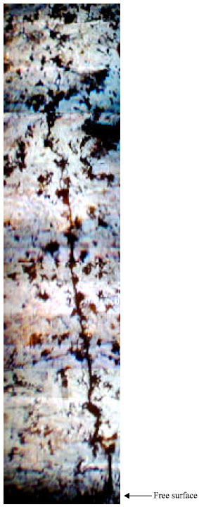
Figure 6 and 7 are micrographs of the crack propagation is SGI and CGI, respectively which the crack coalscences and crack deflection are shown. Linkage of a number of cracks that were indicated early in the fatigue test and the crack arresters are seen. These arresters are mainly the graphite particles and the main crack propagates between them.
In Fig. 8 and 9 two SEM micrographs are shown for the cracks in SGI and CGI. The crack propagation in SGI (Fig. 8) is deflected more than that in CGI (Fig. 9) which means that the crack propagation in SGI is more tortuous.
The stress intensity factor ΔK was calculated using Eq. 14,
| (14) |
| Y | = | Constant (equal to 0.65 for steel and cast iron[12,13]). |
| Δσ | = | Stress range (MPa). |
| a | = | Crack length (mm). Equation 14 can be written for case of tension where, |
| Kmin | = | 0 if σmin is compression, as: |
| (15) |
 | |
| Fig. 6: | Micrograph of crack propagation at 200 Mpa in SGI, N = 8.9x10⁵ cycles, X 120 |
 | |
| Fig. 7: | Micrograph of crack propagation at 200 Mpa in CGI, N = 4.81x10⁶ cycles, X120 |
By substituting fatigue limit σw in place of applied stress (σ) and the value of (d) in place of crack length (a) in Eq. 15, then the values of ΔKth becomes (4.3 MPa m1/2) for SGI and (3.7 MPa m1/2) for CGI. These values are very close to the reported results[5].
The crack propagation rate was calculated using the Paris equation. The results are shown in Fig. 10 and 11. The equations obtained for SGI is,
 | |
| Fig. 8: | SEM topography of crack growth in SGI.X61 |
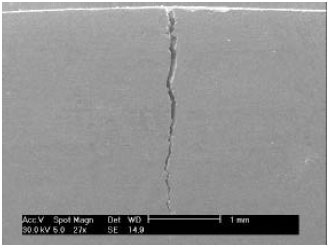 | |
| Fig. 9: | SEM topography of crack growth in SGI.X27 |
da/dN= 3×10⁻⁴ (∆)K) 1.1855 | (16) |
And for CGI,
Da/dN= 3×10⁻⁴ (∆)K) 1.2434 | (17) |
DISCUSSION
Figure 1 shows the S-N curves for ductile cast iron, compacted graphite cast iron and gray cast iron. From the results obtained for each curve, it is obvious that the fatigue life or fatigue resistance for ductile cast iron is more than in compacted graphite cast Iron and the later is greater than in gray cast iron. The fatigue limits determined represent the maximum stress at which the specimens could withstand the load without fracture till 4x10⁷ cycles for SGI, CGI and GCI. The values were (185 MPa) for SGI, (175 MPa) for CGI and (150 MPa) for GCI. These results approached the results obtained by some researchers at similar conditions[10,11].
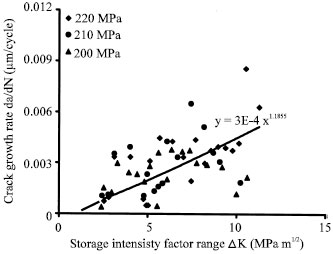 | |
| Fig. 10: | Crack growth rate (da/dN) versus stress intensity factor (ΔK) for SGI |
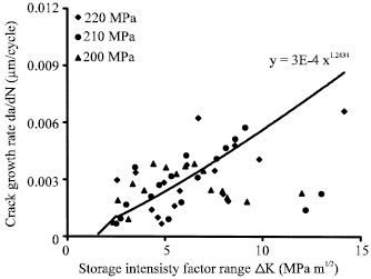 | |
| Fig. 11: | Crack growth rate (da/dN) versus stress intensity factor (ΔK) for CGI |
The small difference between SGI and CGI is attributed to the matrix structure[9], in which the combined effect of nodular graphite in conjunction with higher ferrite percentage of lower σw in SGI is balanced with CGI of lower σw in conjunction with higher pearlite percentage of higher σw.
At about the fatigue limit for each type of material, it was shown that there are some short cracks in the test pieces that did not propagate. So, the fatigue limit represents the maximum stress at which the short cracks produced won’t propagate.
The results obtained from the measurements of crack length in both SGI and CGI show that, the increase in crack length followed an irregular behavior. This is due to the presence of second phase particles (graphite). The presence of casting defects affect this behavior as well. The graphite particles hinder the crack propagation and decrease the crack growth rate, the effect of these crack arresters are obvious in Fig. 2 and 3 for SGI and CGI, respectively where the crack length increase is not smooth with the number of cycles but rather with steps indicating a slowing down in the crack growth rate. The results also show in these figures that the crack growth rates for higher stress levels are faster. The arresters mentioned above are shown clearly in Fig. 4 and 5, where many decreases in Fatigue Crack Propagation (FCP) rate occurs. The first decrease takes place at crack lengths of approximately 400 μm in SGI and 290 μm in CGI. These values are considered as a limit to distinguish between short cracks and long cracks and they are within the range of microstructurally small crack and it can be related to the microstructural unit size as shown by Tokjai and Ogawa[14] through the relation 2 cm = md, where 2 cm is the crack size, m is the multiplication factor and d is the unit size, in this study d represents the graphite particle size which is about 33 μm in SGI and in CGI with an average aspect ratio of 5 (70 μm X 15 μm). The above relation gives for SGI 2 cm = 12 d and for CGI 2 cm = 8 d. The m value mentioned by Tokaji and Ogawa[14] varied between 8-10, while in this study m value varies between 8-12 which are relatively in good agreement and the value of 8 for CGI means earlier transition from short cracks into long cracks. The subsequent arrests in crack propagation rates da/dN occurs at about 352 μm crack spacing in SGI and 339 μm in CGI. By comparing these values with the average graphite particle distance which is about 73 μm in SGI and 62 μm in CGI, it is concluded that not all graphite particles are effective in hindering the FCP, or the main fatigue crack does not propagate between the graphite particles. Transient decreases or arrests in da/dN were observed by Tokaji et al.[16] at distances of 880 μm and 550 μm in coarse grained and fine grained materials respectively. Such variations in da/dN were related to the blocking effect of the grain boundaries and crack deflections. The number of graphite particles covered by these crack spacings in SGI is 4.5 and 5.5 in CGI. The frequency of transient decreases of da/dN due to these barriers vary between 4-5 before the crack propagates finally to cause fracture. The average absolute crack sizes after which no arrests are encountered are 1700 μm in SGI and 1267 μm in CGI. After these crack lengths, the effect of the barriers (graphite particles and the microstructure) disappears and the da/dN increases monotonically with growing crack. The difference in these absolute crack lengths shows the role of the shape factor. The CGI is weaker and cannot sustain cracks as long as in SGI and this is reflected in the ratio of absolute crack length to thickness of the samples. This ratio was 44.74% for SGI and 33.3% for CGI, which means lower fatigue life in CGI, or earlier fracture.
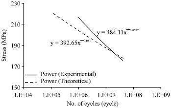 | |
| Fig. 12: | Experimental and theoretical stress versus number of cycles for SGI |
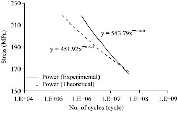 | |
| Fig. 13: | Experimental and theoretical stress versus number of cycles for CGI |
The growth rate of the crack was irregular due to the presence of the graphite particles mainly besides the matrix microstructure. The da/dN was hindered by these particles as shown in Fig. 6 and 7. At early stages of fatigue test, multiple cracks were observed. As the test continued, one main propagating crack immerged which was responsible for the final failure of the fatigue specimen. The higher value for ΔKth in SGI indicates that the effect of crack blunting in this material is more than in CGI. The ΔKth is the value above which the crack will transfer from the graphite to the matrix thus defining the value of which the arrested crack will start propagating[15]. From Fig. 10, 11 it is obvious that the da/dN for both materials are close to some extent with p value in Paris equation for SGI = 1.1855 MPa m1/2 and for CGI = 1.2434. These exponents are relatively low indicating in general good crack growth resistance[3].
A comparison was made between the number of cycles to failure obtained experimentally with those obtained theoretically from the mathematical models employed. The results are shown in Fig. 12, 13 for both SGI and CGI, respectively. They show good agreement, indicating that the mathematical models applied can be used confidently to predict the lifetime of the parts made of these types of materials.
CONCLUSIONS
| 1. | Fatigue strength of the spheroidal graphite cast iron is higher than that in compacted graphite cast irn and the fatigue strength of compacted graphite cast iron is higher than that in gray cast iron. |
| 2. | Graphite shape plays a great role in fatigue life of cast irons, the spheroidal shape of graphite blunts effectively the fatigue crack tip, so, the fatigue life in this type of cast iron is higher. |
| 3. | Since graphite morphology is the most dominant controlling factor in the properties of cast irons, the effects of matrix are of secondary importance. |
| 4. | It was noticed that the fatigue crack propagates between the graphite nodules through the matrix. |
| 5. | Two behaviors of the fatigue cracks are recognized, namely the short and long fatigue cracks separated by a microstructural barrier distance (d). |
| 6. | The crack growth exponent value P in Paris equation is 1.1855 for SGI and 1.2434 for CGI which are closed to the published data for steel. |
| 7. | The number of crack growth arrests varies between 4-5 in both materials. After reaching the final barrier the crack continues to grow monotonically until final fracture. |
REFERENCES
- Shikida, M., Y. Kanayama and H. Nakayama, 1986. Fatigue strength and crack growth behaviors of compacted graphite vermicular cast iron in rotating bending fatigue. Proceedings of the 29th Japan Congress on Material Research, (JCMR'85), Tokyo, Japan, pp: 23-28.
Direct Link